DO YOU KNOW WHERE YOUR CABLES ARE TONIGHT?
←
→
Page content transcription
If your browser does not render page correctly, please read the page content below
PERSPECTIVES ON PV A series of articles on photovoltaic (PV) power systems and the
National Electrical Code by John Wiles
DO YOU KNOW
WHERE YOUR CABLES
ARE TONIGHT?
T
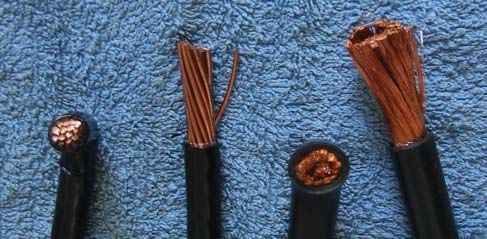
he use of fine stranded, flexible cables appears cable). Both cables are 2/0 AWG (67.4 mm2). The THHN
to be increasing each year. This is particularly Class B cable on the left has 19 separate conductors, each
true with relatively “young” industries like the with a diameter of 0.084in (2.13mm). The THW fine
photovoltaic (PV) industry, the fuel cell indus- stranded cable on the right has 1330 separate conductors,
try, and the uninterruptible power supply (UPS) indus- each with a diameter of 0.01 inch (0.25mm).
tries. In many cases, technicians and installers in these Note that both types of cables are listed in NEC
fields prefer to use fine-stranded flexible cables in the Table 310.13 as suitable for code-compliant installations.
larger sizes (1/0 AWG and up) due to the perceived easier Cables marked with only the DLO (Diesel Locomotive)
installation of these cables compared to the more rigid marking are not suitable for code-compliant installa-
conventional cables. tions, and listed welding cables are only to be used when
Photo 1 shows the differences between a typical stan- attached to the secondary of welding machines under
dard Class B cable and a typical fine stranded cable (some- the requirements of NEC Article 630.
times incorrectly known as diesel locomotive cable or welding Also of note, based on the values in NEC Table 5,
Photo 1. Standard Class B conductor (left) and fine stranded conductor (right)
2 IAEI NEWS January.February 2005 www.iaei.org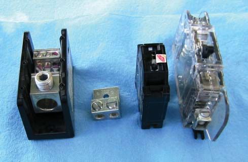
PERSPECTIVES ON PV

Photo 2. Examples of setscrew types of terminals

chapter 9, is the overall diameter of the 2/0 THHN           AWG, and 37 strands in sizes 250-500 kcmil. Conduc-
cable at 0.532 in. (13.51 mm) compared with an overall       tors having more strands than these are widely available
diameter of 0.610 in. (15.49 mm) for the THW. The            and are in different classes such as K and M used for
greater diameter of the fine stranded THW cable is            portable power cords and welding cables. Commonly
mainly due to the thicker insulting jacket required for      used building-wire conductors such as USE, THW,
THW cables. This generally indicates that fewer THW          RHW, THHN and the like are most commonly avail-
cables will fit in a given size of conduit.                   able with Class B stranding but are also readily available
   Reports (unfortunately, mostly anecdotal) have been       (in some locations) with higher quantities of stranding.
received over the last several years about field-made         Fine-stranded cables are frequently used by PV install-
connections in PV and UPS systems that have failed           ers to ease installation and are used in PV systems for
when flexible, fine-stranded cables have been used with        battery cables, power conductors to large utility-interac-
mechanical terminals or lugs that use a set screw to hold    tive inverters and elsewhere.
the wire in the terminal.                                        Some PV modules are supplied with fine-stranded
   These terminals are found on nearly all circuit break-    interconnecting cables (14 AWG–10 AWG) with at-
ers (except those with stud-type terminals), fuse holders,   tached irreversible compression connectors. While these
disconnects, PV inverters, charge controllers, power         crimped-on connectors listed with the module are suit-
distribution blocks, some PV modules, and many other         able for use with the fine-stranded conductors, an end-
types of electrical equipment. Photo 2 shows examples        of-string conductor with mating connector may also be
of a few of these set screw types of terminals.              supplied with the fine-stranded conductor, and the un-
   Fine-stranded conductors and cables are considered        terminated end of that conductor will not be compatible
as those cables having stranding more numerous than          with mechanical terminals.
Class B or C stranding. Class B stranding (the most             According to Underwriters Laboratories (UL)
common) will normally have 7 strands of wire per             Standard 486 A-B, a terminal/lug/connector must be
conductor in sizes 18-2 AWG, 19 strands in sizes 1-4/0       listed and marked for use with conductors stranded in

www.iaei.org                                                                       January.February 2005 IAEI NEWS   3
PERSPECTIVES ON PV
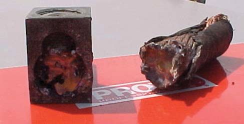
Photo 3. Failed terminal and cable
other than Class B and C. With no marking or factory
literature/instructions to the contrary, the terminal may
only be used with conductors with the most common
Class B and C stranded conductors. These terminals
and lugs are not suitable and should not be used with
fine-stranded cables. UL engineers have said that few
(if any) of the normal screw-type mechanical terminals
that the PV industry commonly uses have been listed
for use with fine stranded wires. The terminal must be
marked or labeled specifically for use with fine-stranded
conductors [see NEC 110.3(A) and (B)].
UL suggests two problems, both of which have been ex-
perienced in PV systems. First, the tightening screw tends
to break the fine wire strands, reducing the amount of cop-
per available to meet the listed ampacity. Second, the initial
torque setting does not hold and the fine strands continue
to compress (creep) after the initial tightening. Even after
subsequent retorquing, the connection may still loosen.
The loosening connection creates a higher-than-normal
resistance connection that heats, loosens even further, and Photo 4. Failed terminal
may eventually fail. A recent example of a failed mechani-
cal terminal from a large PV system is shown in photos 3 be tightened once to the specified torque and there is no
and 4. The terminal had been torqued properly less than retightening specified. Tightening the terminal beyond
three months before the failure. the specified torque value may cause binding of the
threads thereby giving a false torque reading. Both over-
Over-tighten or Retighten? tightening and retightening of listed connectors and
Some installers over-tighten or retighten a connection to terminals on overcurrent devices and other equipment
get fine stranded cable to hold in screw-type terminals. would appear to violate the provisions of the listing and
UL standards for connectors require that the terminal therefore be a violation of NEC Section 110.3(B).
4 IAEI NEWS January.February 2005 www.iaei.org
PERSPECTIVES ON PV

   A quick review of NFPA Standard 70B-2002,
Recommended Practice for Electrical Equipment Main-
tenance, does not find any suggestions that electrical
equipment terminals be periodically retorqued. The
terminals are to be inspected and examined for signs
of looseness or overheating and that situation should
be corrected where found. There is a retorquing recom-
mendation for mechanical fasteners on box covers and
the like.

Solutions
Electrical equipment listed to UL Standards has:
   • Terminals rated for the required current and sized
to accept the proper conductors
   • Sufficient wire bending space to accommodate the
Class B stranded conductors in a manner that meets the       Photo 5. Copper lug—not suitable for fine-stranded cable
wire bending requirements of the NEC
   • Provisions to accept the appropriate conduit size for
these conductors where conduit is required.
    It is therefore unnecessary to use the fine-stranded
cables except possibly when dealing with conductors 4/0
AWG and larger. Experienced electricians and electrical
contractors routinely install the normal, relatively stiff
Class B conductors without difficulty and use parallel-
connected smaller conductors where very large conduc-
tors are required.
    In those cases where a fine-stranded cable must be
used, a few manufacturers make a limited number of           Photo 6. I LSCO FE lug—suitable for fine-stranded cable
crimp-on compression lugs in various sizes that are
suitable for use with fine-stranded cables. These lugs are       Other terminal manufacturers also make pin adapt-
attached to a stud on the device using a washer and nut.     ers (a.k.a. pigtail adapters) that can be crimped on fine-
Most of the commonly used overcurrent devices (both          stranded cables. These pin adapters provide a protrud-
circuit breakers and fuse holders/terminals) come with       ing pin (solid or stranded) that can be inserted into a
screw-type terminals so there is no stud available. Most     standard screw-type mechanical connector. Again, not
of these special crimp-on lugs are solid copper or tinned    all pin adapters/pigtail adapters are listed for use with
solid copper. Photo 5 shows a typical copper light-duty      fine-stranded conductors; some are intended for use
crimp-on lug that is not marked as being suitable for use    with aluminum wire and others provide only a conver-
with fine stranded cables.                                    sion to a smaller AWG size for a B Class conductor.
    Factory-supplied markings and literature indicate           It is suggested that the use of fine-stranded conduc-
which lugs are suitable. An example is the ILSCO FE          tors be avoided wherever possible. Where such cables
series of lugs in sizes 2/0 AWG and larger (see photo        must be used, they should only be terminated with the
6). Burndy makes the YA-FX series of lugs in sizes 8         appropriate connectors/lugs. Previously installed sys-
AWG and larger that have been listed for use with fine        tems should be revisited and the cables replaced where
stranded cables. In both cases the lugs are solid copper.    possible or terminated properly.
It should be emphasized: Most crimp-on lugs are not
listed for use with fine-stranded wire. Where the crimp-      For Further Thought
on compression lugs can be used, they must be installed      Some of the requirements established by UL Standards
using the tools recommended by the manufacturer and,         are of the form: “Don’t do something unless it is spe-
of course, they must be attached to a stud with a nut        cifically allowed by markings on the product or in the
and washer.                                                  instructions.” An example is the use of fine-stranded

www.iaei.org                                                                          January.February 2005 IAEI NEWS   5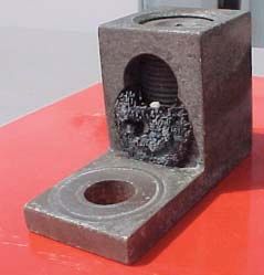
PERSPECTIVES ON PV
cables discussed above. They are not to be used with a For Additional Information
connector or terminal unless that connector or termi- If this article has raised questions, do not hesitate to contact
nal is specifically marked allowing their use. Another the author by phone or e-mail. E-mail:jwiles@nmsu.edu,
example may be the Line and Load markings on circuit Phone: 505-646-6105
breakers where the absence of such markings indicate A PV Systems Inspector/Installer Checklist will be
they are deemed suitable for backfeeding. Most of the sent via e-mail to those requesting it. A copy of the
dc circuit breakers used in the PV industry are marked 100-page Photovoltaic Power Systems and the Nation-
with Line and Load, but are routinely used in a backfeed al Electrical Code: Suggested Practices, published by
configuration on listed equipment. Sandia National Laboratories and written by the au-
Many of these “invisible” requirements were de- thor, will be sent at no charge to those requesting a
veloped decades ago in the early days of the electrical copy with their address by e-mail. The Southwest
power industry. Old-line firms like Square D, GE, T&B, Technology Development web site (http://nmsu.edu/
Westinghouse, and the other manufacturers and users of tdi) maintains all copies of the “Code Corner Col-
electrical equipment have developed in-house procedures umns” written by the author and published in Home
and standards to preserve the “old” corporate knowledge Power Magazine over the last 10 years.
of these hidden requirements over the years as people The author makes 6–8 hour presentations on “PV Sys-
come and go. It appears that “youngster” industries like tems and the NEC ” to groups of 40 or more inspectors,
PV, fuel cells, uninterruptible power systems and the like, electricians, electrical contractors, and PV professionals
may not have developed a means of first discovering and for a very nominal cost on an as-requested basis.
then preserving these “hidden” requirements. Addition-
ally, the testing agencies may be overlooking some of John Wiles works at the Southwest Technology Development Insti-
these “’invisible” requirements in the testing and listing tute (SWTDI) at New Mexico State University. SWTDI has a con-
tract with the US Department of Energy to provide engineering support
of equipment as their corporate memory retires. to the PV industry and to provide that industry, electrical contractors,
The PV Industry (and possibly others) may have to electricians, and electrical inspectors with a focal point for code issues
implement a “search and discover” activity to ferret out related to PV systems. He serves as the secretary of the PV Industry
Forum that submitted 30 proposals for Article 690 in the 2005 NEC.
these hidden requirements, develop methods to preserve He provides draft comments to NFPA for Article 690 in the NEC
the knowledge, and then ensure that they are met by our Handbook. As an old solar pioneer, he lives in a stand-alone PV-power
equipment and systems that must remain safe, reliable, home in suburbia with his wife, two dogs and two cats—permitted and
inspected, of course.
and durable for 30+ years.
Installed or inspected any fine conductor cables re- Th is work was supported by the United States Department of Energy
cently? under Contract DE-FC04-00AL66794
AD ?
6 IAEI NEWS January.February 2005 www.iaei.orgYou can also read