Effect of bottom flange cleat on integrated precast slab and column panel using cold-formed steel
←
→
Page content transcription
If your browser does not render page correctly, please read the page content below
International Journal of Advanced Technology and Engineering Exploration, Vol 8(76)
 ISSN (Print): 2394-5443 ISSN (Online): 2394-7454
 Research Article
 http://dx.doi.org/10.19101/IJATEE.2021.874022

Effect of bottom flange cleat on integrated precast slab and column panel
using cold-formed steel
Sutanto Muliawan1, Anis Saggaff1, Mahmood Bin Md Tahir2, Saloma1*, Muhammad Firdaus3, and
KM Aminuddin1
Civil Engineering Department, Faculty of Engineering, Universitas Sriwijaya, Inderalaya, Indonesia1
Institute for Smart Infrastructure and Innovative Construction (ISIIC), Construction Research Centre (CRC), School
of Civil Engineering, Universiti Teknologi Malaysia, Johor Bahru, Malaysia 2
Civil Engineering Department, Faculty of Engineering, Universitas Persatuan Guru Republik Indonesia, Palembang,
Indonesia3

Received: 07-February-2021; Revised: 22-March-2021; Accepted: 25-March-2021
©2021 Sutanto Muliawan et al. This is an open access article distributed under the Creative Commons Attribution (CC BY)
License, which permits unrestricted use, distribution, and reproduction in any medium, provided the original work is properly
cited.

 Abstract
 The use of cold-formed steel currently develops very fast. It is due to its advantages such as durability, stability, non-
 combustibility, sustainability, and cost-effectively. On the other hand, its disadvantages are difficult to connect, low fire
 resistance, residual stress on the cross-section that affects buckling resistance. In the previous research, to overcome the
 lack of buckling resistance in cold-formed steel, the composite connection is proposed. A recent study about cold-formed
 steel connection is divided into non-composite and composite research. The result of composite research has a higher
 moment capacity than non-composite. Most of the composite research is focused on beam and column with the concrete
 slab above the beam. In the current study, a T-shaped of gusset plates is used as a joint connector. This study aims to
 investigate the effect of the bottom flange cleat on the joint capacity. The slab panel's material is a Lipped Channel
 Section with the size of 12524 as the frames and reinforcements. The grade of cold-formed steel is fy = 530 MPa and fu =
 590 MPa, while the T-shaped plate connector's strength is S355. The bolt used has a diameter of 10 mm, fy = 800 MPa.
 The flange cleats used is L100×100×10×80. The parametric study was conducted based on Eurocode 3. The connection
 with the additional bottom flange cleat has a higher moment resistance than without the flange cleat. The additional
 bottom cleat's influence is that the moment resistance increased the moment resistance from 17.11 kNm to 23.32 kNm.
 The predicted failure mode of the connection could be the failure that occurred at the top side of the cold-formed section
 of the slab due to the bending.

 Keywords
 Cold-formed steel connection, Bottom flange cleat, Integrated precast slab, Joint flexural resistance, T-shaped plate
 connector.

1.Introduction The development of technology leads to the massive
Cold-Formed Steel (CFS) is lightweight steel product of CFS. CFS became more popular and well-
produced by forming the thin plate in cool condition. accepted in any region in the world [1]. There are still
It became widely used for any purpose of household very few studies on the composite connection of
furniture and light construction elements from the cold-formed steel [2−5]. Throughout the research, the
middle of the twentieth century. CFS could be used concrete is considered as normal concrete with fc’=
as purlin, roof cover, steel truss, wall panel, 30 MPa until fc’= 43 Mpa, with the result of those
composite deck slab, and structural framing. One of studies were moment-rotation, failure mode, and load
the disadvantages is the buckling problem which deflection. The type of connection is a rectangular
reduces the maximum load. gusset plate [3, 4] and a haunched gusset plate with
 seat angles [2, 5].

 The non-composite research about cold-formed steel
*Author for correspondence connection is about the bolt connection with various
 gusset plates [6−10]. The type of connection for the

462
International Journal of Advanced Technology and Engineering Exploration, Vol 8(76)

non-composite is rectangular gusset plate [6], and stiffness can be generated. Furthermore,
rectangular gusset plate with flange cleat [7], connection behaviour can also be investigated.
haunched gusset plate [8], welded connection [9], and
T-Shaped gusset plate [10]. Aminuddin et al. [6] examined the beam to column
 joints of bare build up cold-formed steel connected
Both composite and non-composite had an addition by rectangular gusset plates 10 mm thick,
to the flange-cleat connection [2, 5, 7]. The flange- experimentally and analytically. The beam depth
cleat connection is related to fast installation and lack varies from 200mm,250mm, and 300mm, and the
of expensive welding processes. The flange cleats are same column size (depth=300mm). The experimental
often used to reinforce the joint in the existing results show that the beam depth should be limited to
structure. The investigation of concrete slab obtain ductile joint behaviour. The study was
combines with cold-formed steel as the primary beam continued with the same type of connection, but with
was conducted [11-15]; the purpose of those study is the addition of top angle and seat angle with a
to find out the behaviour of the cold-formed thickness of 6 mm Aminuddin et al. [7]. The
component within the slab shear connector comparison of the two specimens shows that the
configuration [11, 12, 15] and beam variation [13, influence of the top and seat angle could increase the
14]. moment capacity and stiffness of the connection.

Based on recent research, the beam-column Firdaus et al. [8] continued the research on non-
composite connection shown that the beam section is composite joints that Aminuddin had done. The beam
located outside the slab part. In this study, there is a and column dimensions are the same as previous
difference in beam location with the previous studies [6, 7], but the haunched gusset plate was
research [2−5]. The beam is located inside the slab selected. This shape was chosen to avoid premature
part, and there is no study about the encase beam- buckling of the gusset plate. A total of 6 specimens
column connection before. The encase beam does not were carried out experimentally, three specimens
require a space outside the slab part. Therefore, a used gusset plates only, and the remaining specimens
wider space below the concrete slab can be produced. were reinforced with top angle, seat angle and web
The precast panel slab with a 1 × 1-meter size using a angle. The experimental results also show an increase
cold-formed steel section will be connected by a T- in moment capacity by 20% and 30% for stiffness. It
shape connection to the precast column panel with a means that the addition of seat angle components can
1 × 3-meter size of the CFS section. This study aims be used as a recommendation to increase the joint's
to compare the maximum moment capacity of the strength without having to dismantle the structure as
previous study without the bottom flange cleat and a whole.
with the additional bottom flange cleat. This paper's
method is limited by a parametric study based on BS The weakness of bare cold-formed steel tends to
EN 1993-1-1 and BS EN 1993-1-8. lateral torsion due to the thin plates' behaviour, which
 can be overcome by the integration of CFS beams
It is hoped that the result of this study will be useful and concrete slabs as part of the composite. However,
for the researchers who investigate the same slab the knowledge of lightweight steel composite joints is
panel with or without integration with concrete. still limited. The intensive research on the
 lightweight steel composite joints with gusset plates
2.Literature review has been carried out experimentally and analytically
Generally, the research on bare steel cold-formed by Firdaus et al. [16]. Furthermore, Firdaus et al. [17]
steel (CFS) is to obtain the best performance of the proposed tools software to predict connection
connection and should be simple and easy to install. capacity because it requires many calculations,
The use of CFS was growing rapidly and leads to the iterative, trial, and error. A total of six specimens
main components of the structure, however, without were studied with dimensions of beam DLC200,250,
being balanced with design standards and because of 300, respectively, and column with DLC300. The
the lack of related literature. The established code of two types of connection were investigated, the first
standards recently still focused on hot-rolled steel type using gusset plates and web stiffener, and the
joints. Therefore, several CFS studies have been second type is the same as the first type but with the
carried out through parametric and experimental addition of a seat angle placed on the bottom beam
approaches by applying a monotonic loading at the flange. The experimental results show that increasing
end of the beam so that the joint's moment of rotation the seat angle could increase 8% for the moment

463
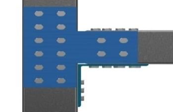
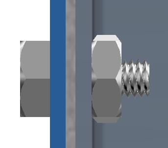
Sutanto Muliawan et al.

resistance and 17% for the joint's stiffness. However, in the slab. The author claims that this is a new
the presence of a seat angle makes the connection method of utilizing lightweight steel as part of the
lead to full-strength joint behaviour. structural member. The experimental and Finite
 element tests were carried out with two specimens,
Although several studies have shown the potential of where CS-1 used 4 CFS and CS-2 used 3 CFS which
CFS as an alternative material, applying that material were installed on the plate. CS-1 provides superior in
as part of the main structure has not yet been terms of strength and ductility to CS-2. This is the
established. Lawan et al. [18] was argued in their confirmation of a positive contribution from CFS
paper that CFS could be used as the primary beam, elements as a substitute for conventional rebars. The
but it is limited to small and medium buildings. This parametric studies regarding the CFS slab connection
statement is based on his research on composite to the column have been studied by Muliawan et al.
beams, combined with shear connectors from bolts [10]. It is based on the fact that the calculation
with sizes M12, M14, and M16, beam dimensions procedure not available. In addition, the application
with DLC250 and DLC300 [14]. The Four-point of composite slabs as part of the building can only be
bending test procedure was conducted, and the used if there is an adequate connection to transfer the
flexural capacity of the experiment is considered slab load to the column. The dimensions of CFS with
sufficient to be categorized as the primary beam. 12524 was selected as beams and columns. The
 gusset plate with 4mm thick is used as a connecting
Furthermore, Salih et al. [15] was investigated a medium between beams and columns by applying
lightweight steel composite beam. The beam various bolts M10, M12, M14, and M16. From the
configuration was installed through-bolts to connect analysis, it can be concluded that M10 and M12 bolts
the lipped channel back to back (I-shape) and toe to can be applied to these joints. While M16 bolts can
toe (box-shape). This study demonstrated that CFS only be used for beams with dimensions more than
sections could be fabricated easily because of the CFS12524 because of the unfulfilled range of validity
lightweight material. Self-Compacted Concrete that has been set in EC3.
(SCC) was used to fill material for concrete beams
and slabs. Composite behaviour is achieved by 3.Methods
attaching a shear connector made of U-shape rebar. In this study, there are two kinds of specimens. IJT-1
The bending test shows that the I-shape profile could for specimen without flange cleat and IJT-2 for
provide 24.2% more capacity than the box-shape, specimen with flange cleat. The IJT-1 specimen is
even though the cross-section and volume of the shown in Figure 1, and the IJT-02 specimen
material used are identical. It could be due to the configuration in Figure 2. The full-scale sample of
higher moment of inertia of the I-shape, which shows this current study is shown in Figure 3. The column
that back-to-back lipped channel could provide height is 3000 mm, and the width of 1000 mm. The
economic savings. column is made by CFS with Lipped Channel (LC)
 12524 profile. The length of the slab is 1000 mm and
Qiao et al. [19] has investigated the research on 1000 mm in width. The Double Lipped Channel
concrete slabs with CFS, where the CFS was cast in (DLC) 12524 CFS profile is placed in the middle of
the concrete slab. This method directly eliminates the column and the slab. For CFS profile design
local buckling of the thin plate due to concrete strength is Fy = 530 MPa, Fu = 590 MPa.
surrounding the CFS profile. Also, the volume of
concrete will be reduced due to the existence of CFS

464
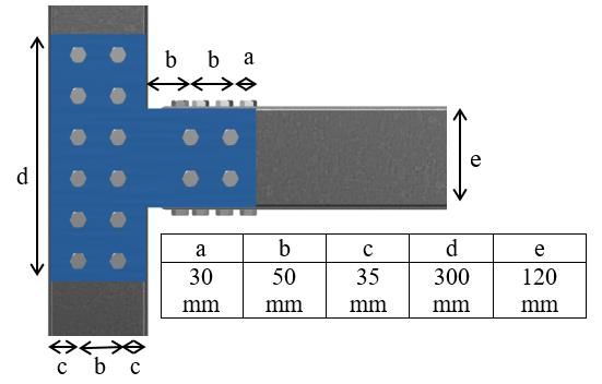
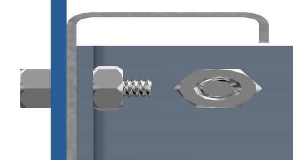
International Journal of Advanced Technology and Engineering Exploration, Vol 8(76)

Figure 1 IJT-01 Specimen in right and front side view

 Column Part

 Slab Part

 Bolt M10

 Flange Cleat with Slab Part
 M10 bolt Flange Cleat with
 T-shaped Gusset Plate 4 M10 bolt
 mm thickness
Figure 2 IJT-02 Specimen in the right and front side view

There is a bolt connection with a T-Shaped gusset
plate to connect the slab and column. The bolts are
designed based on BS EN 1-8:2005 [20]. All bolts
grade are 8.8, with the ultimate strength (Fu) is 800
MPa. The bolts stress area (As) is 58.0 mm2. The T-
shaped plate had a thickness of 4 mm with S355
grade (Fy = 355 MPa, Fu= 510 MPa) based on BS EN
1-1: 2005[21]. The T-Shape connection is shown in
Figure 4.

 Figure 3 The actual specimen
465
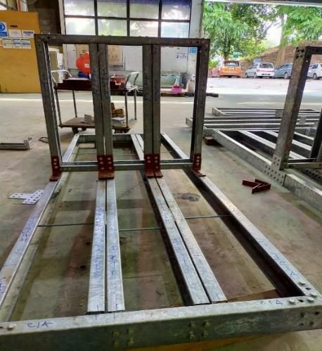
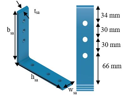
Sutanto Muliawan et al.

The channel lips section could be seen in Figure 5. The minimum horizontal spacing between the bolt
The channel lips profile used in this research is LC (p1) had to be calculation below.
12524. The detail is the thickness (t) 2.4 mm, height Minimum es = 2,2d0 (3)
(h) 125 mm, broad (b) 50 mm, and lips (c) 15 mm. Maximum es = 14t (4)
There is a flange cleat with grade S355, fy = 275 Bolt configuration on the vertical direction (p 2) is
MPa, fu = 430 MPa. The bottom flange cleat calculated below.
component is shown in Figure 6. Minimum ev = 2,4d0 (5)
 Maximum ev = 14t (6)
For bolt spacing configuration on the gusset plate is
based on BS EN 1-8:2005 [20], there is edge distance The analytical method is based on the component
between the bolt and the edge of the plate. The steel method. There is a flowchart of the study shown in
specimen is exposed to the weather and other Figure 7. First, collecting the component data such as
corrosive influences. From BS EN 1-8:2005 [20], a bolt, gusset plate, angle clamp, cold-formed steel,
M10 bolts the hole diameter (d0) is 11 mm. Based on and bottom flange cleat data. Then, do the parametric
BS EN 1-8:2005, the range validity of bolts as calculation based on BS EN 1993-1-8:2005. The IJT-
follows: 01 and IJT-02 specimens are being calculated in this
Minimum ef = 1.2d0 (1) study. Then, after the calculation has finished for
Maximum ef = 4(t)+40 mm (2) both specimen, there is a result comparison between
d0 is the hole diameter, and t is the thickness of the IJT-01 and IJT-02.
thinner outer connected part.

Figure 4 T-shape plate connection

Figure 5 Cold-formed steel section Figure 6 Flange cleat

466
International Journal of Advanced Technology and Engineering Exploration, Vol 8(76)

According to BS EN 1993-1-8:2005, there is a shear each component and the arm's lever. So, the equation
resistance of bolt calculation in equation 18. The is
bearing resistance in equation 19. Mj,a = Minimum value between bearing and shear at
 side gusset plate x number of bolt x lever arm (9)
Fv,Rd = (7)
 2
 Mj,b = Minimum value between bearing and shear at
 middle gusset plate x number of bolt x lever of arm
Where αv is 0.6 for bolt grade 8.8; fub is the ultimate (10)
strength of bolt (MPa), and As is the stress area of the Mj,gp = 2 x Mj,a + 2 x Mj,b (11)
bolt (mm2). The moment capacity with the additional bottom
 2.5 ,
Fb,Rd = (8) flange cleat is shown in equations 12 and 13.
 2
 Madd = fy,sa x w (12)
Where αb = 1; kt = 1; fu,comp is the ultimate strength of Where fy,sa is the yield strength of bottom flange
the component (MPa); dbolt for the diameter of the cleat, and w is elastic section modulus of bottom
bolt (mm); tbeam is the thickness of the component flange cleat.
(mm). The bearing resistance component is CFS,
gusset plate, angle clamp, and bottom flange cleat. Mtotal = Mj,gp + 6(Madd) (13)
The moment capacity of the middle part (Mj,a) and
the side part of the specimen (Mj,b) are affected by
the minimum value of shear and bearing resistance in

 Start

 Parametric data:
 Cold formed material properties
 Bolt data
 Gusset plate data
 Cold-formed steel data
 Angle clamp data
 Bottom flange cleat data

 Parametric calculation:
 Bolt resistance
 Shear resistance
 Bearing resistance
 Potential resistance of bolt group
 Moment capacity

 Finish

Figure 7 Research flowchart

4.Result bolt holes (d0 ) is 11 mm. The validity of the bolt on
4.1 Range validity the gusset plate is shown in Table 1.
The minimum and maximum edge distance for the
M10 bolt are shown in the calculation below. The Minimum e1 = 1.2d0

467
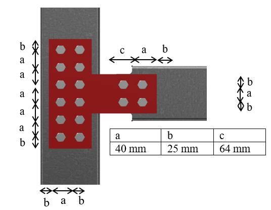
Sutanto Muliawan et al.

 = 1.2 (11) Maximum p1 = 14t
 = 13.2 mm = 14(4)
Maximum e1 = 4(t)+40 mm = 56 mm
 = 4(4) + 40
 = 56 mm For minimum and maximum vertical spacing
 between bolts is shown in the calculation below.
The minimum and maximum horizontal spacing
between the bolt (p1) calculation is based on BS EN Minimum p2 = 2,4d0
1-8:2005 [20]. The bolt minimum and maximum = 2.4(11)
horizontal spacing are shown in the calculation = 26.4 mm
below. Maximum p2 = 14t
 = 14(4)
Minimum p1 = 2.2d0 = 56 mm
 = 2.2(11)
 = 24.2 mm

Table 1 Range validity
 Min. edge Spacing Max. edge
 Flange cleat Position Status
 Spacing (mm) (mm) spacing (mm)
 Side 13.2 20 56 Ok
Side Gusset Plate Horizontal 24.2 50 56 Ok
 Vertical 26.4 50 56 Ok
 Side 13.2 22.5 56 Ok
 Middle Gusset Horizontal 24.2 37.5 56 Ok
 Plate Vertical 37.5 Ok
 26.4 56

4.2 IJT-01 specimen calculation
The shear capacity and bearing capacity of the bolt
are calculated below.
 0.6 800 58
Fv,Rd = = = 22.272 kN
 2 1.25
 2.5 , , 2.5 590 10 2.36
Fb,Rd,Cfs = = = 27.848 kN
 2 1.25
 2.5 , 2.5 510 10 4
Fb,Rd,gp = = = 40.8 kN
 2 1.25
 2.5 , 2.5 510 10 4
Fb,Rd,ac= = = 40.8 kN
 2 1.25

Shear and bearing capacity is influenced by the gusset plate's moment capacity at the side position is
contact plane between plate and bolt. The bearing influenced by the lever arm, as shown in Figure 9.
plane and shear plane for the side gusset plate is The lever arm for the side gusset plate is 35.36 mm,
shown in Figure 8. The gusset plate calculation at and the moment capacity is calculated below.
the side position result is shown in Table 2. The

Table 2 The side gusset plate calculation result
 Shear plane Bearing capacity Shear capacity
 Component Bearing plane
 (kN) (kN)
 Bolt - 2 - 44.544
 Side Gusset Cold-formed Steel 1 - 27.848 -
 Plate Gusset Plate 1 - 40.8 -
 Angle Clamp 1 - 40.8 -

468
International Journal of Advanced Technology and Engineering Exploration, Vol 8(76)

 cv = 2
 cbp= 1

 Shear resistance plane
 Bearing resistance plane
Figure 8 The bearing and shear plane on the side gusset plate

Figure 9 Lever of arm for side gusset plate

Mj,a = 4 x 35.36 x 27.85 = 3.938 kNm
The bearing plane and shear plane for the middle The moment capacity of the gusset plate at middle
gusset plate is shown in Figure 10. The middle position is influenced by the lever arm in Figure 11.
gusset plate calculation result is shown in Table 3. The lever arm for the middle gusset plate is 28.29
 mm, and the moment capacity is calculated below.

 cv = 2

 cbp= 1

 Bearing resistance plane Shear resistance plane

Figure 10 The Bearing and shear plane on the middle gusset plate

Table 3 The middle gusset plate calculation result
 Shear plane Bearing capacity Shear capacity
 Component Bearing plane
 (kN) (kN)
 Bolt - 2 - 44.544
Middle Gusset
 Cold-formed Steel 2 - 55.7
Plate
 Gusset Plate 1 - 40.8

469
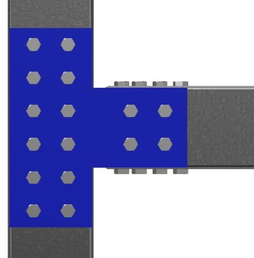
Sutanto Muliawan et al.

Figure 11 Lever of arm for middle gusset plate

Mj,b = 4 x 28.29 x 40.8 = 4.616 kNm because of the additional bending moment produced
Total moment capacity of the connection for IJT-01 from the angle section. The calculation is shown
is: below.
Mj = 2 Mj,A + 2 Mj,B = 2 x 3.938 + 2 x 4.616= 17.11 kNm Madd = fy,sa x w= 355 MPa x (1/6 x 502 x 7)mm4 = 1,04
The final result for IJT-01 is 17.11 kNm, and it is kNm
matched to the previous study [10]. Total moment capacity of the connection for IJT-02
 is
 Mj = 17.11 + 6(1.04) = 23.32 kNm
4.3 IJT-02 specimen calculation
The cold-formed steel, gusset plate, and angle clamp The moment capacity comparison between IJT-01
in IJT-02 are typical of IJT-01. Therefore, the and IJT-02 is shown in Table 4. The moment
moment capacity of the gusset plate for IJT-02 is capacity of connection has improved when the
similar to IJT-01. As shown in Figure 12, the bottom bottom flange cleat is added.
flange cleat could increase the moment resistance

 M

Figure 12 Bottom flange cleat additional moment

Table 4 Moment capacity comparison
IJT-01 Moment capacity (kNm) IJT-02 Moment capacity (kNm)
17,11 23,32

5.Discussion capacity.
According to Table 2, the gusset plate at the side
position is possible to fail at bearing failure at the The moment capacity for IJT-01 is 17.11 kNm, and
beam bolt hole. The bolts' bearing resistance (27.848 the bearing resistance is less than shear resistance.
kNm) at cold-formed steel is very small rather than The moment capacity of IJT 02 (23.32 kNm) is more
the gusset plate or the angle clamp. Bolt shear than the IJT 01 (17.11 kNm). This proves that the
capacity has a high value rather than the bearing seat angle section could increase the joint capacity. In
capacity of cold-formed steel, gusset plate, and angle this paper, the calculation procedure was proposed,
clamp in the specimen's side part. Subsequently, it and the elastic behaviour was assumed according to
could be predicted that the connection would not fail component method (BS EN 1993-1-8 and BS EN
because of shear. At the middle part of the specimen, 1993-1-3).
the bolt shear capacity is high rather than the gusset
plate's bearing capacity. There is a possibility that 6.Conclusion and future work
gusset plate failure will occur in the middle part Based on this research, it is clear that the two
because the gusset plate's bearing capacity is very specimens, the bolt shear capacity has a high value
low compared with cold-formed or bolt shear rather than the bearing capacity. It caused by the

470
International Journal of Advanced Technology and Engineering Exploration, Vol 8(76)

grade of the bolt is high enough to resist the shear rectangular gusset plate with angle cleat connections
failure. The bearing resistance is influenced by the for cold-formed steel section. In IOP conference
other connected components, such as the gusset plate, series: materials science and engineering 2020 (pp. 1-
cold-formed steel, and angle clamp for the side gusset 8). IOP Publishing.
 [8] Firdaus M, Saggaff A, Tahir MM, Aminuddin KM,
plate. The weakest part on the side connection is at Ngian SP, Siang TC, et al. Behavior of partial strength
the CFS because the bearing plane for CFS is 1. The of beam-to-column connection with gusset plate for
weakest part of the middle connection is at the gusset cold-formed steel sections. ASEAN Engineering
plate because the CFS has more bearing planes than Journal. 2020; 10(2):99-114.
the gusset plate bearing plane. The moment capacity [9] Hanisha CS, Kishore IS. Experimental and finite
of the connection is the results from the calculation of element analysis of cold formed steel beam-column
each component of the connection. By installing the joint. Materials Today: Proceedings. 2020; 33(1):480-
flange cleat, the connection capacity is increase. The 3.
effect of bottom flange cleat installation has [10] Muliawan S, Saggaff A, Mahmood T, Firdaus M,
 Aminuddin KM. Loading capacity calculation of
improved the connection moment capacity from integrated precast slab and column panel using cold-
17.11 kNm to 23.2 kNm. The future work to be formed steel. In journal of physics: conference series
recommended is to add one more flange cleat at the 2021 (pp. 1-7). IOP Publishing.
top of the connection between the cold-formed steel [11] Armo AA, Saggaff A, Tahir MM, Ngian SP, Sulaiman
reinforced slab and column panel. It is recommended A, Salih MN. Behaviour of rebar shear connector in a
to make a sub-assemblage frame specimen of the push test for composite beam with cold-formed steel
connection. section. In IOP conference series: materials science
 and engineering 2019 (pp.1-10). IOP Publishing.
Acknowledgment [12] Salih MN, Tahir MM, Mohammad S, Ahmad Y,
None. Sulaiman A, Shek PN, et al. Experimental study on
 flexural behaviour of partially encased cold-formed
 steel composite beams using rebar as shear connector.
Conflicts of interest
 In IOP conference series: materials science and
The authors have no conflicts of interest to declare.
 engineering 2019 (pp. 1-8). IOP Publishing.
 [13] Khadavi MM, Salih MN, SA AA, Shek PN. Behaviour
References of composite beam arranged as boxed-section with c-
[1] Yu WW, Laboube RA, Chen H. Cold-formed steel channel of cold-formed steel of lipped section. In IOP
 design. Hoboken: Wiley; 2010. conference series: materials science and engineering.
[2] Saggaff A, Firdaus M, Tahir MM, Ngian SP, Siang 2020 (pp.1-9).
 TC, Aminuddin KM, et al. Experimental study on [14] Lawan MM, Shek PN, Tahir MM. Flexural
 composite connection with double lipped c-sections. performance of cold-formed steel section in a
 In IOP conference series: materials science and composite beam system. In IOP conference series:
 engineering 2020 (pp. 1-9). IOP Publishing. materials science and engineering 2020 (pp. 1-12).
[3] Amsyar F, Siang TC, Sulaiman A, Khun MC. IOP Publishing.
 Numerical and experimental study of semi-rigid beam- [15] Salih MN, Tahir MM, Mohammad S, Ahmad Y, Shek
 to-column composite connections in cold-formed PN, Abraham A, et al. Bending experiment on a novel
 steel. In AIP conference proceedings 2020. AIP configuration of composite system using rebar as
 Publishing LLC. shear connectors with partially encased cold-formed
[4] Sulaiman A, Salleh NM, Sukardi N, Siang TC, steel built-up beams. Materials Today: Proceedings.
 Saggaff A. Experimental evaluation of composite 2021; 39(2):999-1005.
 beam-to-column joint using cold-formed steel [16] Firdaus M, Saggaff A, Tahir M, Ngian SP, Sulaiman
 sections. In IOP conference series: materials science A, Salih MN. Experimental and analytical study on
 and engineering 2019 (pp.1-13). IOP Publishing. composite connection with cold-formed steel of
[5] Firdaus M, Saggaff A, Tahir MM, Aghlara R, double channel sections. In IOP conference series:
 Sulaiman A, Aminuddin K, et al. Influence of seat materials science and engineering 2019 (pp. 1-10).
 angles on the behaviour of cold-formed steel concrete IOP Publishing.
 composite joints. Journal of Constructional Steel [17] Firdaus M, Saggaff A, Tahir MM, Ngian SP, Sulaiman
 Research. 2020. A. Prediction of moment resistance of steel connection
[6] Aminuddin K, Saggaff A, Tahir MM, Ngian SP, with macro excel using eurocode standard. In journal
 Sulaiman A, Firdaus M, et al. Analytical and of physics: conference series 2019 (pp. 1-10). IOP
 experimental investigation on slip-in gusset plate Publishing.
 connection for double c-channel sections of cold- [18] Lawan MM, Shek PN, Tahir MM. Can cold-formed
 formed steel. The Open Civil Engineering Journal. steel section be use as a sustainable structural member
 2019; 13:210-7. in building and civil engineering constructions? a mini
[7] Aminuddin KM, Saggaff A, Tahir MM, Ngian SP,
 Sulaiman A, Firdaus M, et al. Behaviour of
471
Sutanto Muliawan et al.

 review. In IOP conference series: materials science Saloma is a lecturer in the Civil
 and engineering 2020 (pp. 1-13). IOP Publishing. Engineering Department, Faculty of
[19] Qiao W, Yan X, Zhu R, Wang F, Wang D. Flexural Engineering, Sriwijaya University,
 properties of new cold-formed thin-walled steel and Indonesia. She received a Doktor in
 concrete composite slabs. Journal of Building Civil Engineering from Institut
 Engineering. 2020. Teknologi Bandung in 2014. She is
[20] Standard B. Eurocode 3—design of steel structures—. Head of Graduate of Civil Engineering
 BS EN 1993-1-8:2005. at Sriwijaya University. Her research
[21] https://shop.bsigroup.com/ProductDetail?pid=000000 focuses on Geopolymer Concrete, Nanomaterial Concrete,
 000030283899. Accessed 26 October 2020. Lightweight
 Auts PhotoConcrete, Reactive Powder Concrete, Self-
 Compacting Concrete, Cold-Formed Steel, and Light-
 Sutanto Muliawan is PhD student of weight Construction
 Civil Engineering, Faculty of Email: salomaunsri@gmail.com
 Engineering, Sriwijaya University. He
 is lecturer in the Civil Engineering Muhammad Firdaus is a lecturer in
 Department, Faculty of Engineering, Civil Engineering Department, Faculty
 Sriwijaya University, Indonesia. His of Engineering, Universitas Persatuan
 research focuses on Foam Concrete, Guru Republik Indonesia, Palembang,
 Cold-Formed Steel, and Light-weight Indonesia. He received a Doktor in
Construction Civil Engineering from Sriwijaya
 Authssutantomuliawan@yahoo.com
Email: Photo University in 2019. His research
 focuses on Lightweight Concrete, Self
 Anis Saggaff is a Professor in the Civil Compacting Concrete, Cold-Formed Steel, and Light-
 Engineering Department, Faculty of AuthsConstruction.
 weight Photo
 Engineering, Sriwijaya University, Email: firdaus@univpgri-palembang.ac.id
 Indonesia. He received a Doktor in
 Civil Engineering from University KM Aminuddin is a lecturer in the
 Teknologi Malaysia. He is Rector of Civil Engineering Department, Faculty
 Sriwijaya University. His research of Engineering, Sriwijaya University,
 focuses on Geopolymer Concrete, Indonesia. He received a Doktor in
Nanomaterial Concrete, Lightweight Concrete, Reactive Civil Engineering from Sriwijaya
 Auths Concrete,
Powder Photo Self Compacting Concrete, Cold-Formed University in 2019. His research
Steel, and Light-weight Construction. focuses on Lightweight Concrete,
Email: anissaggaf@yahoo.com Cold-Formed Steel, and Light-weight
 Construction.
 Mahmood Md Tahir is a lecturer in Aut skmaminuddin@ft.unsri.ac.id
 Email: Photo
 Institute for Smart Infrastructure ad
 Innovative Construction (ISIIC),
 Construction Research Centre (CRC),
 School of Civil Engineering, Universiti
 Teknologi Malaysia, Johor Bahru,
 Malaysia. His research focuses on
 Lightweight Concrete, Cold-Formed
Steel, and Light-weight Construction.
Email:hoto
 mahmoodtahir@utm.my

472
You can also read