Electronic Code Lock Circuit Using 555 Timer - ijirset
←
→
Page content transcription
If your browser does not render page correctly, please read the page content below
ISSN (Online) : 2319 - 8753
                                                                                      ISSN (Print) : 2347 - 6710

International Journal of Innovative Research in Science, Engineering and Technology
    An ISO 3297: 2007 Certified Organization                        Volume 7, Special Issue 1, March 2018
  6th National Conference on Frontiers in Communication and Signal Processing Systems (NCFCSPS '18)
                                           13th-14th March 2018
                                                Organized by
      Department of ECE, Adhiyamaan College of Engineering, Hosur, Tamilnadu, India

     Electronic Code Lock Circuit Using 555
                     Timer
              Keerthiga.M1, Kiruthiga.K2, Nandhini.R4, Poornamathi.V4 and Chidambaram.S5
           UG Scholar, Department of ECE, Adhiyamaan College of Engineering, Hosur, TN, India1,2,3,4
         Associate Professor, Department of ECE, Adhiyamaan College of Engineering, Hosur, TN, India5

 ABSTRACT: In the Technological world, almost all the gadgets are digitalized. They are designed with
microcontrollers and Raspberry Pi chip.Those microcontrollers have complex code and they are not reusable.
They are meant to do a specific task with specific time which has already been predefined by the designer. To
overcome the above mentioned mess, we are going to design the analog based electronic code lock circuit using
555 timer. In this circuit, the complexity is reduced and it is cost efficient comparing to the digital code lock
circuit. If any malfunctioning occur, it can be easily replaced with minimum wastage because there will be no
serious damages. The supply level to this circuit is also limited between +3V and +12V.It can be used for
security purpose where user interface is needed.

KEYWORDS: Monostable Multivibrator, Trigger Mechanism, Timer, Electronic Lock.

                                              I.INTRODUCTION

Digital code locks are very popular in electronics, where you need to enter a particular ‘Code’ to open the lock.
This type of locks needs a microcontroller to compare the entered code with the predefined code to open the
lock. We have already built these kinds of digital locks using Arduino, using Raspberry Pi and using 8051
microcontroller. But, here we are building the code lock without any microcontroller. When the specific code
has been given, the output voltage will be high, the motor rotates and the door will be unlocked. If the code has
been entered wrongly the motor doesn’t rotate and hence the IC will be in reset position. The unlock time can be
varied using the resistor and capacitor. Time delay generation of Timer application has been used in this circuit.

                                            II. RELATED WORKS

Zungeru A.M. et al [1] proposed that the insecurity and crime constitute some of the major problems facing our
immediate society today. People live with fear of being attacked by burglars, vandals and thieves. Despite all the
effort, resources and time that has been devoted to the development of tools that will reduce crime rates and
make the world a safer place to live, these problems are still on the increase. These gave rise to the need for an
increasing development in the technology of alarm systems which utilizes various principles such as infrared
motion detection, light (photo) sensitive electronic devices and so on. Even with the introduction of these alarm
systems which have reduced greatly the level of insecurity, there is still a problem of false alarm which needs to
be minimized. Jing Yanget al [2] proposed that Computers, mobile devices and the Internet hasbecome an
impartible part of life for many people. Since 1999, the number of Internet users has increased tenfold and
reached around 40% of the word population in 2014. Besides, more than half of the U.S. population nowadays
own a smartphone and spend an average of two hours per day on their mobile devices2. Many of our daily
activities (for example, banking, shopping, and social activities are accomplished in a virtual manner with the
aid of Internet and mobile devices. However, the information privacy and security issues have not attracted
sufficient attention from individual uses, although they have been discussed on media for quite a long time. It is
still prevalent for many online users to repeatedly use the same password for multiple accounts, which is a
severe security vulnerability. Bhaskar Mondal et al [3]suggested that Internet has been a corridor for
cybercrimes. The facility of internet has conveyed is immense but at the cost of data privacy. When two entities

Copyright to IJIRSET                                         www.ijirset.com                                  177
ISSN (Online) : 2319 - 8753
                                                                                        ISSN (Print) : 2347 - 6710

International Journal of Innovative Research in Science, Engineering and Technology
     An ISO 3297: 2007 Certified Organization                           Volume 7, Special Issue 1, March 2018
  6th National Conference on Frontiers in Communication and Signal Processing Systems (NCFCSPS '18)
                                            13th-14th March 2018
                                                  Organized by
      Department of ECE, Adhiyamaan College of Engineering, Hosur, Tamilnadu, India

are communicating, security of the data being switched is mandatory. Data needs to be concealed when it is
communicated over an open network to safeguard it from intruders. For this need cryptography and encryption
algorithms are proposed which are depends on some secret, the sender and receiver agree with. Secure
communication between two or more entities involves a concealed cryptographic key. Privacy of this key is a
vital aspect of secure communication. A poised key agreement protocol certifies the security of the key.

                                   III. EXPERIMENTAL MATERIALS

IC 555 TIMER

The 555 timer comes in two packages, either the round metal-can called the 'T' package or the more familiar 8-
pin DIP 'V' package. About 20-years ago the metal-can type was pretty much the standard (SE/NE types). The
556 timer is a dual 555 version and comes in a 14-pin DIP package, the 558 is a quad version with four 555's
also in a 14 pin DIP case.

                                            Fig 1: Pin Diagram of 555 Timer
PUSH BUTTON

A push-button or simply button is a simple switch mechanism for controlling some aspect of a machine or
a process. Buttons are typically made out of hard material, usually plastic or metal. The surface is usually flat or
shaped to accommodate the human finger or hand, so as to be easily depressed or pushed. Buttons are most
often biased switches, although many un-biased buttons (due to their physical nature) still require a spring to
return to their un-pushed state.Different people use different terms for the "pushing" of the button, such as press,
depress, mash, hit and punch.

DC MOTOR

A DC motor is any of a class of rotary electrical machines that converts direct current electrical energy. into
mechanical energy. The most common types rely on the forces produced by magnetic fields. Nearly all types of
DC motors have some internal mechanism, either electromechanical or electronic, to periodically change the
direction of current flow in part of the motor.

                                     IV. METHODS AND TECHNIQUES

Inside the 555 timer, the equivalent of over 20 transistors, 15 resistors, and 2 diodes, depending of the
manufacturer. The equivalent circuit, in block diagram, providing the functions of control, triggering, level
sensing or comparison, discharge, and power output. Some of the more attractive features of the 555 timer are:
Supply voltage between 4.5 and 18 volt, supply current 3 to 6 mA, and a Rise/Fall time of 100 nSec. It can also
withstand quite a bit of abuse. The Threshold current determine the maximum value of Ra + Rb. For 15 volt
operation the maximum total resistance for R (Ra +Rb) is 20 MΩ.

Copyright to IJIRSET                                            www.ijirset.com                                 178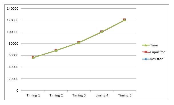
ISSN (Online) : 2319 - 8753
                                                                                                    ISSN (Print) : 2347 - 6710

International Journal of Innovative Research in Science, Engineering and Technology
     An ISO 3297: 2007 Certified Organization                                   Volume 7, Special Issue 1, March 2018
   6th National Conference on Frontiers in Communication and Signal Processing Systems (NCFCSPS '18)
                                                  13th-14th March 2018
                                                         Organized by
       Department of ECE, Adhiyamaan College of Engineering, Hosur, Tamilnadu, India

                                          Fig 2: System Architecture of electronic code lock

The supply current, when the output is 'high', is typically 1 milli-amp (mA) or less. The initial monostable timing accuracy is
typically within 1% of its calculated value, and exhibits negligible (0.1%/V) drift with supply voltage. Thus long-term
supply variations can be ignored, and the temperature variation is only 50ppm/°C (0.005%/°C). All IC timers relay upon an
external capacitor to determine the off-on time intervals of the output pulses. It takes a finite period of time for a capacitor (C)
to charge or discharge through a resistor (R). Those times are clearly defined and can be calculated given the values of
resistance and capacitance.
Assume that the capacitor is initially discharged. When the switch is closed, the capacitor begins to charge through the
resistor. The voltage across the capacitor rises from zero up to the value of the applied DC voltage. The time that it takes for
the capacitor to charge to 63.7% of the applied voltage is known as the time constant (t). That time can be calculated with the
simple expression: t = R X C Assume a resistor value of 1 MΩ and a capacitor value of 1uF. The time constant in that case is:
                                              t = 1,000,000 X 0.000001 = 1 second

Assume further that the applied voltage is 6 volts. That means that it will take one time constant for the voltage across the
capacitor to reach 63.2% of the applied voltage. Therefore, the capacitor charges to approximately 3.8 volts in one second.
 As mentioned earlier, here 555 IC is configured in Monostable Multivibratior mode. So once the trigger is given by
 pressing the Push Button, LED will turn ON and output will stay HIGH until capacitor connected at PIN6 charges to the
 peak value. The time for which the OUTPUT will be high can be calculated by the below formula.
                                                        T = 1.1*R*C
 So according to values in our circuit, T = 1.1*47000*0.0001 = 5.17 seconds. So the Motor will rotate for 5seconds.Now,
 we know that in 555 timer IC, no matter what the TRIGGER is, if the RESET pin is pulled down the output will be LOW.
 So here we will use the Trigger and Reset.

                                   V. SELECTION OF RESISTOR AND CAPACITOR

 The time delay generation in this circuit depends on two values i.e. the capacitor and the resistor value. The resistor
 connected at pin 8 and the capacitor between the pin 6 and pin 7 determines the unlock time. We can change the timing
 value by varying t capacitor and resistor value. The various timing value with varying resistor and capacitor values is
 given in the table below

                                             Table 1 Selection of Resistor and Capacitor

                               S.No         RESISTOR             CAPACITOR                 TIME
                                               (Ω)                  (F)                     T(S)
                                  1           56K                   120                       7
                                  2           68K                   130                      10
                                  3           82K                   150                      14
                                  4           100K                  180                      20
                                  5           120K                  220                      30

Copyright to IJIRSET                                                    www.ijirset.com                                       179
ISSN (Online) : 2319 - 8753
ISSN (Print) : 2347 - 6710
International Journal of Innovative Research in Science, Engineering and Technology
An ISO 3297: 2007 Certified Organization Volume 7, Special Issue 1, March 2018
6th National Conference on Frontiers in Communication and Signal Processing Systems (NCFCSPS '18)
13th-14th March 2018
Organized by
Department of ECE, Adhiyamaan College of Engineering, Hosur, Tamilnadu, India
VI. RESULTS AND DISCUSSIONS
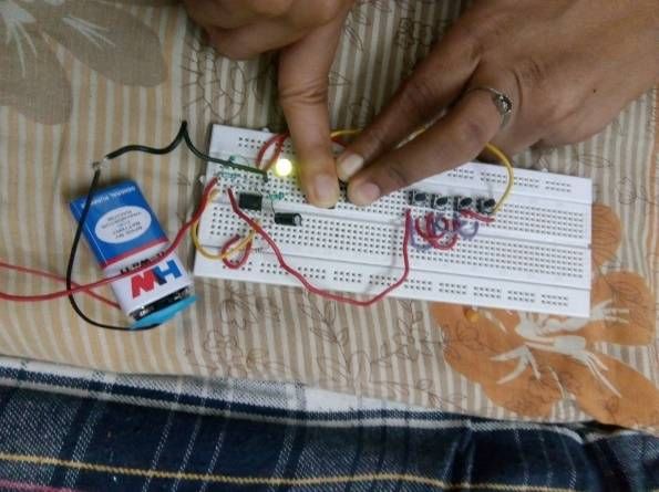
When the power supply is given, the trigger is given to pin 2 of the IC and the DC motor starts running
indicating the unlocked door.
Fig 3: Output using LED
Fig 4: Time response curve for different values of resistor and capacitor
VII. CONCLUSION
We designed and implemented the concept of electronic code locker system using 555 Timer IC. This
experimental analysis shows that the electronic code locker system provides the easy way to ensure the security
in locker system. We presently implemented with four combinations of code words and this can be further
modified with many combinations so that the efficiency of the locker system can be improved.
REFERENCES
[1] Zungeru, A...M., Kolo, J.G., & Olumide, I. (2012), “A Simple and Reliable Touch sensitive security System”, International Journal of
Network Security & Its Applications (IJNSA), 4(5), pp.149–165.
[2] Jing Yang QR Codes and Authentication Protection School of Business and Economics State University of New York at,Oneonta, NY
13820, USA [Jing.yang@oneonta.edu]
Copyright to IJIRSET www.ijirset.com 180ISSN (Online) : 2319 - 8753
ISSN (Print) : 2347 - 6710
International Journal of Innovative Research in Science, Engineering and Technology
An ISO 3297: 2007 Certified Organization Volume 7, Special Issue 1, March 2018
6th National Conference on Frontiers in Communication and Signal Processing Systems (NCFCSPS '18)
13th-14th March 2018
Organized by
Department of ECE, Adhiyamaan College of Engineering, Hosur, Tamilnadu, India
[3] Bhaskar Mondal et al “A Key Agreement Scheme for Smart Cards Using Biometrics”, Department of Computer Science and
Engineering, National Institute of Technology Jamshedpur, India- 831014 [bhaskar.cse@nitjsr.ac.in]
[4] William Klieber, “Automated Code Repair Based on Inferred Specifications”, Will Snavely Software Engineering Institute Carnegie
Mellon University{weklieber, wsnavely}@cert.org
[5] Theraja, B. L., & Theraja, B.K (2002), “A textbook of Electrical Technology”, S. Chand and Company Ltd. New Delhi, India 2002, pp.
220, 920, 924, 1712 – 1716.
[6] Weber, & Thad-L. (1985), “Alarm Systems and Theft Protection”, 2nd edition, Stoncham, MA: Utterworth, pp. 7-8.
[7] Graw-Hill, M.C. (1985), “Encyclopedia of Science and Technology (5th Edition)”, Cambridge University Press 1985, ISBN 042507843,
pp. 2-253.
[8]Zungeru, A.M. et al. (2012), “Design and Implementation of a Low Cost Digital Bus Passenger Counter”, Innovative Systems Design and
Engineering, 3(4), pp. 29–4
Copyright to IJIRSET www.ijirset.com 181You can also read


