Bearings ENGINEERING MANUAL FOR INDUSTRIAL APPLICATIONS

Page created by Carl Potter
 
CONTINUE READING
Bearings ENGINEERING MANUAL FOR INDUSTRIAL APPLICATIONS
T R EL L EB O RG S E A L I N G S O LU T I O N S

              Orkot                                          ®
                Bearings
                     ENGINEERING MANUAL FOR INDUSTRIAL APPLICATIONS

           YO U R PA R T N ER F O R S E A L I N G T EC H N O LO GY

3024_Orkot_EngeneeringGuide_PMS_DD_3.1.indd 1                         28.02.2014 11:43:26
Bearings ENGINEERING MANUAL FOR INDUSTRIAL APPLICATIONS
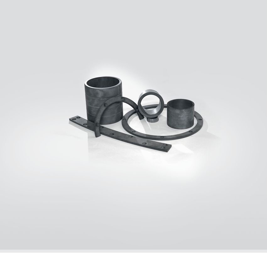
Orkot_eng-man_gb.qxp:gb                       18.03.2008             17:33 Uhr            Seite 2

               Orkot® Bearings
               Engineering manual for industrial applications

          Your Partner for Sealing Technology
          Trelleborg Sealing Solutions is a major international developer,                proprietary compounds and a range of unique products.
          manufacturer and supplier of seals, bearings and molded                         Trelleborg Sealing Solutions fulfills challenging service
          components in polymers. We are uniquely placed to offer                         requirements, supplying standard parts in volume or a single
          dedicated design and development from our market-leading                        custom-manufactured component, through our integrated
          product and material portfolio: a one-stop-shop providing the                   logistical support, which effectively delivers over 40,000 sealing
          bestTrelleborg
                in elastomer,   silicone,
                           Sealing         thermoplastic,
                                    Solutions                  PTFE andgroup
                                                  is an international      composite      products
                                                                                specialized in        to customers
                                                                                                    Facilities        worldwide.
                                                                                                               are certified to ISO 9001:2000 and ISO/TS 16949:2002.
          technologies    for applications
              polymer technology,             in aerospace,
                                       uniquely                 industrial
                                                    placed to offer         and design and
                                                                       dedicated                    Trelleborg Sealing Solutions is backed by the experiences and
          automotive    industries.
              development     from our market leading product and material portfolio;     Facilitiesresources
                                                                                                     are certified
                                                                                                                 oftoone
                                                                                                                      ISO 9001:2008   and ISO/TS
                                                                                                                           of the world's         16949:2009.
                                                                                                                                            foremost  experts in polymer
              a one-stop shop providing the best in elastomer, thermoplastic, PTFE        Trelleborg   Sealing Solutions
                                                                                                    technology,  Trelleborg is
                                                                                                                             AB.backed by the experience
          Withand
                50 composite
                    years of experience,    Trelleborg
                                 technologies           Sealingand
                                                   for sealing    Solutions
                                                                      bearingengineers    and
                                                                               applications in resources of Trelleborg Group, one of the world’s foremost
          support   customers
              aerospace,          with design,
                            industrial,           prototyping,
                                         and automotive          production, test and experts in polymer technology.
                                                             industries.
          installation using state-of-the-art design tools. An international
          network
              With of   over 70experience,
                     50-years     facilities worldwide
                                                 Trelleborgincludes
                                                              Sealingover   20 manu-
                                                                         Solutions  engineers
          facturing
              supportsites, strategically-positioned
                         customers                       research andproduction,
                                       with design, prototyping,          developmenttest and                ISO 9001:2000                     ISO/TS 16949:2002
          centers,   including
              installation      materials
                             using           and development
                                      state-of-the-art    design laboratories     and
                                                                     tools. An international      ISO 9001:2008                     ISO/TS 16949:2009
          locations
              network specializing
                         of over 70in facilities
                                        design and     applications.
                                                    worldwide    includes 30 manufacturing
              sites, strategically positioned research and development centers,
          Developing
              includingand  formulating
                         materials  andmaterials   in-house,
                                          development         we utilizeand locations
                                                          laboratories
          the specializing
               resource of in
                            our material
                              design anddatabase,    including over 2,000
                                          applications.                                                                  The information in this manual is intended to be for general reference purposes only and is not
                                                                                                                         intended to be a specific recommendation for any individual application. The application limits for
                                                                                                                         pressure, temperature, speed and media given are maximum values determined in laboratory
                                                                                                                         conditions. In application, due to the interaction of operating parameters, maximum values may not
               Developing and formulating materials in-house, we utilize the                                             be achieved. It is vital therefore, that customers satisfy themselves as to the suitability of product
               resourcein of
          The information    thisour    material
                                  brochure           database,
                                            is intended             including
                                                        to be for general         over
                                                                          reference      2,000
                                                                                    purposes       proprietary
                                                                                              only and
                                                                                                                         and material for each of their individual applications. Any reliance on information is therefore at the
                                                                                                       is not intended to be a specific recommendation for any individual application.
                                                                                                                         user's own risk. In no event will Trelleborg Sealing Solutions be liable for any loss, damage, claim or
               compounds
          The application        and
                          limits for    a range
                                     pressure,      of unique
                                                temperature, speedproducts.
                                                                    and media given are maximum values determined inexpenselaboratory   conditions.
                                                                                                                                    directly         In application,
                                                                                                                                             or indirectly  arising or due  to thefrom
                                                                                                                                                                        resulting  interaction
                                                                                                                                                                                        the useofofoperating
                                                                                                                                                                                                     any information provided in this
          parameters, maximum values may not be achieved. It is vital therefore, that customers satisfy themselves as        to the While
                                                                                                                         manual.    suitability
                                                                                                                                           everyofeffort
                                                                                                                                                   productis and
                                                                                                                                                              madematerial   for each
                                                                                                                                                                     to ensure         of their individual
                                                                                                                                                                                  the accuracy    of information contained herewith,
                                                                                                                         Trelleborg
          applications. Any reliance on information is therefore at the user‘s own risk. In no event will Trelleborg Sealing         Sealing
                                                                                                                              Solutions       Solutions
                                                                                                                                         be liable       cannot
                                                                                                                                                    for any  loss,warrant
                                                                                                                                                                   damage, theclaim
                                                                                                                                                                                accuracy  or completeness
                                                                                                                                                                                     or expense   directly of information.
                Trelleborg
          or indirectly arising Sealing
                                or resultingSolutions     fulfills
                                             from the use of        challenging
                                                             any information providedservice    requirements,
                                                                                      in this brochure. While every effort is made to ensure the accuracy of information contained herewith,
                supplying
          Trelleborg           standard
                     Sealing Solutions        parts
                                          cannot      in the
                                                 warrant  volume
                                                             accuracyoror a single custom-manufactured
                                                                          completeness  of information.                  To obtain the best recommendation for a specific application,   please
                                                                                                                            contact your local Trelleborg Sealing Solutions marketing company.
               component, through our integrated logistical support, which
          To obtain the best recommendation for a specific application, please contact your local Trelleborg Sealing Solutions marketing company.
               effectively
          This edition         delivers
                       supersedes            over
                                  all previous      40,000
                                               brochures.        sealing
                                                          This brochure or anyproducts
                                                                               part of it mayto
                                                                                              not customers
                                                                                                                     This edition supersedes all previous brochures.
                                                                                                  be reproduced without
                                                                                                                     Thispermission.
                                                                                                                          brochure or any part of it may not be reproduced without permission.
               worldwide.
          ® All trademarks are the property of Trelleborg Group. The turquoise color is a registered trademark of Trelleborg
                                                                                                                       ® All trademarks are theTrelleborg
                                                                                                                              Group. © 2014,     property of Trelleborg
                                                                                                                                                          Group.         AB. reserved.
                                                                                                                                                                   All rights
                                                                                                                            The turquoise color is a registered trademark of Trelleborg AB.
                                                                                                                            © 2008 Trelleborg AB. All rights reserved.

          2 ˙ TRELLEBORG SEALING SOLUTIONS                                                                                       Lastest information available at www.tss.trelleborg.com ˙ Edition February 2014

          2

3024_Orkot_EngeneeringGuide_PMS_DD2.indd 2                                                                                                                                                                  13.03.2014 16:13:48
Bearings ENGINEERING MANUAL FOR INDUSTRIAL APPLICATIONS
Orkot_eng-man_gb.qxp:gb     18.03.2008   17:33 Uhr      Seite 3

     Contents

      General:                                                                          Page
                                     Orkot®Materials                                     4
                                     Quality                                             4
                                     R+D and Test Facilities                             5
                                     Availability                                        5
                                     Grades                                              6

      Properties / Specifications:                                                      Page
                                     Mechanical Properties                               7
                                     Thermal Properties                                  8
                                     Electrical Resistance                               8
                                     Radiation Resistance                                9
                                     Chemical Resistence                                 9
                                     Swell                                              11
                                     Food and Potable Water Contact                     11
                                     PV and Coefficient of Friction                     11
                                     Un-lubricated or Boundary Lubrication Conditions   12
                                     Hydrodynamic Applications                          12
                                     Grease lubrication                                 12

      Design information:                                                               Page
                                     Interference Fit                                   13
                                     Wall Thickness                                     13
                                     Machining Tolerances                               13
                                     Clearance                                          14
                                     Bore Closure                                       14
                                     Design Service                                     14

      Design / Installation:                                                            Page
                                     Lamination Direction                               15
                                     Counter Face                                       15
                                     Installation                                       15
                                     Application Checklist                              16
                                     Machining Orkot®                                   16

                                                                                               3
Bearings ENGINEERING MANUAL FOR INDUSTRIAL APPLICATIONS
Orkot_eng-man_gb.qxp:gb      18.03.2008    17:33 Uhr    Seite 4

      General

      Orkot®Materials
      Orkot®bearing materials are a range of thermoset composite       Many successful applications for Orkot®involve highly loaded
      bearing materials incorporating advanced polymer                 bearings or pads operating with intermittent or oscillating
      technologies. These consist of technical fabrics impregnated     movements.
      with thermosetting resins, evenly dispersed solid lubricants
      and further additives to ensure the optimum solution is          Manufacturing composite bearings since 1954, Orkot®
      reached to satisfy many engineering applications.                bearings have been fitted and used by thousands of satisfied
                                                                       customers world-wide in a diverse range of applications,
      Orkot®materials have many advantages over more traditional       including:
      metallic bearing materials and other polymeric bearings          • Railways
      including:
                                                                       • Off-road vehicles
      • Low coefficient of friction
                                                                       • Process equipment
      • High load capacity
                                                                       • Injection molding machines
      • Good chemical resistance
                                                                       • Pumps and Valves
      • Operates in fresh or salt water without lubrication
                                                                       • Lifting and handling equipment
      • Damping of vibration
                                                                       • Hydropower
      • Accommodation of shaft misalignment
                                                                       • Formula 1 racing cars
      • Ease of machining
                                                                       • Roll coverings
      • Fitting by pressing, freezing, adhesives and mechanical
                                                                       • Ports, harbors, sluices, sea defense barriers
        methods
                                                                       • Merchant and Navy Shipbuilding (specialized engineering
      • Dimensional stability
                                                                         manual available on marine applications)
      • Minimal thermal softening
      • Does not encourage galvanic corrosion
      • Orkot®contains no asbestos or environmentally
        hazardous/toxic substances

      Quality
      All Orkot®bearings manufactured are subject to strict quality    Accreditation is supported by procedures and processes to
      controls and procedures, from raw material acquisition through   ensure full traceability of each component.
      manufacturing to delivery.
                                                                       A continuous test program ensures the quality and performance
      Certification of the production facility is in accordance with   of Orkot®bearing materials, and this can be further supported
      international standard BS EN ISO 9001:2000 and meets the         by specific testing and certification of products for customers if
      specific requirements for quality control and management of      required.
      purchasing, production and marketing functions.

  4
Orkot_eng-man_gb.qxp:gb      18.03.2008    17:34 Uhr     Seite 5

     General

     R+D and Test Facilities
     The testing laboratories at the factories are equipped to carry
     out tribological and mechanical tests. Tribological tests are
     conducted both in linear and rotary geometries, either dry or
     externally lubricated with fluids (oil, grease, water, etc). Wear
     and friction data are obtained against a range of counter
     faces, including those specific to a customer application.
     Mechanical tests include compressive, tensile, flexural, shear
     and hardness testing.

                                                                         Oscillating test rig

     Availability
     Orkot®bearing materials are usually supplied as fully
     machined components to customers' own drawings.
     Alternatively, semi-finished materials are supplied in the form
     of tube or sheet. The following standard range of sizes is
     available with other sizes on request:

       Tube
                    Minimum ID                8 mm

                    Maximum OD                2,000 mm

                    Standard lenghts          340, 500 and 670 mm

       Sheet
                    Minimum thickness         1 mm

                    Maximum thickness         50 mm

                    Maximum width             600 mm

                    Maximum lenght            2,000 mm

                                                                         Orkot®Bearings

                                                                                                5
Orkot_eng-man_gb.qxp:gb           18.03.2008       17:34 Uhr       Seite 6

      General

      Grades
      Orkot®bearings are manufactured in a range of grades using                        Many other grades have been developed, even for unusual
      different combinations of fabrics, resins and additives designed                  applications, employing different combinations of standard and
      to satisfy many applications.                                                     specialized fabrics, additives and resin systems.

      The commonly used grades have been designated as standard                         Please contact TSS Product Management to discuss any
      grades, these are shown in the table below.                                       projects with unusual conditions for which a special grade may
                                                                                        be required.

        Grade                Properties                      Typical Applications                                                        Coefficient of Friction,
                                                                                                                                         typical dry
                                                                                                                                                 dry**

        C320                 standard grade                  used against carbon steel, treated surfaces, ceramic or chrome              0.15 – 0.20
                                                             plated counter face

        C321                 high electrical resistance      electrical insulators, food applications and structural parts               0.15 – 0.20

        C322                 standard grade                  used against stainless steel counter face, where water is                   0.15 – 0.20
                             operating in water              present or electrical insulation required

        C324                 high temperature or             railway brake systems, withstanding high temperature and                    0.20 – 0.35
                             chemical resistance             offering thermal insulation

        C335 / C361          low swell rate and              used against stainless steel counter face, with intermittent                0.15 – 0.20
                             resistance to sea water         water contact or where electrical insulation is required
                             with limited dry running
                             capability

        C338                 high temperature or             guide bearings for high temperature applications                            0.20 – 0.25
                             chemical resistance
                             with added lubricants

        C369                 dry running, low friction,      used against carbon steel, treated surfaces, ceramic or chrome              0.05 – 0.10
                             reduced stick-slip and          plated counter face
                             extended life

        C378                 dry running, low friction,      used with stainless steel counter face, where water is present              0.05 – 0.10
                             reduced stick-slip and          or electrical resistance required
                             extended life

        C380                 high wear resistance and        standard wear ring material for use in hydraulic cylinders, see             0.15 – 0.20
                             good sliding properties         separate specialized application catalog for more information

        C410                 silent operation,               materials handling equipment and industrial processing,                     0.05 – 0.10
                             stick-slip minimized,           off highway heavy lift and transport,
                             dry running capability          fluid power when stick-slip or poor lubrication are issues

      * The coefficient of friction values indicated are typical only and can vary with load, speed, counter face material and any contamination present.

  6
Orkot_eng-man_gb.qxp:gb       18.03.2008     17:34 Uhr     Seite 7

     Properties / Specifications

     Properties / Specifications
      Orkot®Grade                  C320 / C321 / C322           C324 / C338                                         C369 / C378                      C410
                                   C335 / C361 / C380

      Ultimate Compressive         300                          350                                                 280                              280
      Strength (N/mm2)

      Shear Strength (N/mm2)       80                           80                                                  80                               80

      Tensile Strength (N/mm2)     55                           60                                                  55                               55

      Compressive Modulus of       2800                         3400                                                2800                             2800
      Elasticity (N/mm2)

      Hardness (Rockwell M)        100                          105                                                 100                              80

      Density (g/cm3)              1.25                         1.25                                                1.25                             1.25
     Note, all data based on tests to BS EN ISO 604:1997, BS EN ISO 178:1997, BS 2782:1993 and Orkot®standard methods.

     Mechanical Properties
     Under compressive load, standard Orkot®grades behave in an
     elastic manner up to a yield point. Beyond this, permanent                                           350
     deformation may occur. The yield point relates to the shape of                                                                            ULTIMATE COMPRESSIVE STRENGTH

     the part and to some extent to the operating temperature.                                            300
                                                                                 BEARING PRESSURE N/mm2

                                                                                                          250
     To keep a safe distance from the yield point when designing
     a bearing, our general recommendation is for most static                                             200

     applications a maximum design load of 80 N/mm2, with                                                 150
     40 N/mm2 maximum for dynamic applications.
     However, dynamic application is also dependant on the                                                100

     PV (pressure × velocity) value (see page 12).
                                                                                                           50

     These values are with fully supported bearing surfaces and                                            0

     forces perpendicular to the laminations. For forces applied                                                0         10        20         30          40     50           60

     parallel to the laminations, such as on the end face of a                                                                 % DEFLECTION OF WALL THICKNESS
     flanged bush, only light loads should be used, typically to a
     maximum of 40 N/mm2 for static loading and 20 N/mm2 for                  Typical deflection under load for a cylindrical bearing
     dynamic. Higher loads may require the use of, for example,
     separate thrust washers made from a flat laminate sheet.                 As with all composite bearings, the effective Elastic Modulus
                                                                              in an application for Orkot®materials is very dependent upon
     Higher load values than those indicated above have been used             the shape of the component and the support provided for it.
     for specific applications.                                               Modulus values for Orkot®standard grades range from
                                                                              800 N/mm2 to 3000 N/mm2. Thus, calculating the deformation
     Please contact TSS Product Management for assistance if your             of a pad or the degree by which a shaft moves off the center
     applications exceeds these values.                                       line when under load is complex and depends on the wall
                                                                              thickness, any shaft misalignment and the bearing clearance.

                                                                              Please contact TSS Product Management for assistance if
                                                                              bearing deflection is important in your application.

                                                                                                                                                                                    7
Orkot_eng-man_gb.qxp:gb         18.03.2008      17:34 Uhr      Seite 8

      Properties / Specifications

      Thermal Properties
      Orkot®materials have low thermal conductivity and operate as                    Application at the extremes of temperature depends on the
      thermal insulators. As with all polymer bearing materials, the                  design of the component and the fixation method used. For
      thermal expansion of Orkot®must be taken into consideration                     example, an interference fit can be used from -30 °C to +60 ºC
      during the design process, particularly when operating at                       whereas a split ring mounted in a groove housing can be used
      higher temperatures or with components having thick sections.                   between -60 °C and +130 ºC.
      As a laminate material, the coefficient of thermal expansion is
      different perpendicular or parallel to the layers.                              Grades C324 and C338 were specifically developed for high
                                                                                      temperature applications.
      The wall thickness of a bush should be kept to a minimum to
      limit the effect of thermal expansion and to better control                     Please contact TSS Product Management for advice on
      clearance levels.                                                               cryogenic or high temperature applications.

       Property                                                                        Standard Grades                     High Temperature Grades
                                                                                                                           C324 / C338

       Coefficient of thermal expansion                                10 -5/°C        9 – 10                              4–5
       perpendicular to laminations                                                    (-40 °C to +130 °C)                 (-40 °C to +250 °C)

       Coefficient of thermal expansion                                10 -5/°C        5–6                                 2–3
       parallel to laminations                                                         (-40 °C to +130 °C)                 (-40 °C to +250 °C)

       Thermal Conductivity                                            W/m °K          0.293                               0.169

       Minimum and maximum operating temperatures*                                     Cryogenic to +130 °C                Cryogenic to +250 °C

      * Correct operation at upper extremes of temperature depends upon application

      Electrical Resistance
      Orkot®materials are suitable for applications in which                          C321 should normally be used and the properties for this are
      interference with magnetic or electric fields must be                           indicated below:
      prevented. They also exhibit electrical insulation properties
      and have been used in many electrical applications in                            Property                                                   Value
      generators, motors, switches and transformers.

      Orkot®is non-magnetic and does not build up static charges
                                                                                       Insulation resistance MOhm                                 2000
      and can be used as a general construction material in the
      electrical engineering industry.                                                 Dielectric strength at +90 °C, V/mm                        210
                                                                                       (perpendicular to the fabric laminations)

                                                                                       Dielectric constant up to 1 MHz (permittivity)             3.1

  8
Orkot_eng-man_gb.qxp:gb         18.03.2008   17:34 Uhr   Seite 9

     Properties / Specifications

     Radiation Resistance
     Orkot®components have been successfully used in nuclear                While these changes may be very small, please contact
     and irradiated environments. However, as with all polymer              TSS Product Management to discuss applications.
     materials, the mechanical properties of Orkot®are effected by
     exposure.

     Chemical Resistance
     Orkot®materials are resistant to many chemicals. They do not           Chemical resistance is affected by many issues such as
     corrode and are unaffected by many solvents, inorganic                 temperature, concentration, etc. Over the years the
     solutions and weak acids. Water based chemicals can also act           manufacturer collected substantial application and laboratory
     as lubricants. Standard grades are attacked by chemicals such          testing information and will be pleased to review any
     as ketones, chlorinated solvents, strong alkalis and hot strong        application involving aggressive media. However, the following
     oxidizing agents. However, C324 and C338 grades provide                table provides some information regarding the chemical
     additional chemical resistance.                                        resistance of standard grades and C324 / C338:

                                                            A       B                                                          A      B
      Acetaldehyde                                          N       N         Carbon Dioxide Gas                               Y       Y
      Acetic Acid 75 %                                      N       Y         Carbon Monoxide Gas                              Y       Y
      Acetic Acid Glacial                                   N       N         Carbon Tetrachloride                             Y       Y
      Acetone                                               N       N         Carbon Tetrachloride Vapour                      Y       Y
      Alcohol, Amyl                                         Y       Y         Chlorine Hydrochloric Acid Wet 10 %              Y       Y
      Alcohol, Butyl                                        N       Y         Chlorine Dry Gas                                 Y       Y
      Alcohol, Ethyl                                        N       N         Chlorine Wet Gas                                 Y       Y
      Ammonia Liquified Gas                                 N       N         Chloroform                                       N       N
      Ammonia Gas                                           N       N         Chromic Acid                                     N       Y
      Ammonium Hydroxide                                    N       N         Citric Acid                                      Y       Y
      Benzene                                               N       Y         Copper Nitrate                                   Y       Y
      Bleaches                                                                Cumene                                           N       Y
      - Calcium Hyperchlorite                               Y       Y         Cyclohexane                                      N       Y
      - Chlorine Dioxide Wet                                Y       Y         Deionized Water                                  Y       Y
      - Hydrogen Peroxide                                   Y       Y         Demineralized Water                              Y       Y
      - Lithium Hyperchlorite                               Y       Y         Detergents Organic pH 9 – 12                     Y       Y
      - Peroxides Dilute                                    Y       Y         Detergents Organic pH > 12                       N       Y
      - Sodium Hyperchlorite < 18 %                         Y       Y         Diesel Fuel                                      Y       Y
      Brine                                                 Y       Y         Diethyl Ether                                    N       N
      Bromine Dry Gas                                       N       N         Distilled Water                                  Y       Y
      Bromine Liquid                                        N       N         Ethanol                                          N       N

     A = C320 / C321 / C322 / C335 / C361 / C369 / C378 / C410              Y = Acceptable in application
     B = C324 / C338                                                        N = Unsuitable for application
     All data refers to temperatures up to +50 °C, beyond this consult TSS Product Management

                                                                                                                                             9
Orkot_eng-man_gb.qxp:gb          18.03.2008   17:34 Uhr    Seite 10

       Properties / Specifications

                                                            A        B                                            A   B
        Ethyl Acetate                                       N        N          Methyl Alcohol (Methanol) 100 %   N   N
        Ethylene Glycol                                     Y        Y          Methyl Ethyl Ketone               N   N
        Fatty Acids                                         Y        Y          Naphtha                           Y   Y
        Fluorine Gas                                        N        N          Naphthalene                       Y   Y
        Formaldehyde                                        N        Y          Nitric Acid 5 %                   Y   Y
        Formic Acid                                         N        N          Nitric Acid 10 %                  Y   Y
        Gasoline/Petroleum Leaded                           Y        Y          Nitric Acid 20 %                  N   Y
        Gasoline/Petroleum Aviation                         Y        Y          Nitric Acid 40 %                  N   N
        Gasoline/Petroleum Unleaded                         N        Y          Oil Crude Sour                    N   Y
        Glucose                                             Y        Y          Oil Crude Sweet                   N   Y
        Glycerine                                           Y        Y          Oleum                             N   N
        Glycol                                              Y        Y          Olive Oils                        Y   Y
        n-Heptane                                           Y        Y          Peroxide Bleach                   Y   Y
        Hexane                                              Y        Y          Phenol                            N   N
        Hydrobromic Acid < 25 %                             Y        Y          Phosphoric Acid                   Y   Y
        Hydrobromic Acid 50 %                               N        Y          Potassium Hydroxide 25 %          Y   Y
        Hydrobromic Acid 60 %                               N        N          Potassium Hydroxide 45 %          N   Y
        Hydrochloric Acid < 25 %                            Y        Y          Propylene Glycol                  Y   Y
        Hydrochloric Acid 40 %                              N        Y          Sodium Chloride                   Y   Y
        Hydrochloric Acid + Organics                        N        N          Sodium Hydroxide 10 %             Y   Y
        Hydrofluoric Acid 10 %                              N        Y          Sodium Hydroxide 25 %             N   Y
        Hydrofluoric Acid 20 %                              N        N          Sodium Hydroxide 50 %             N   Y
        Hydrogen Bromide Wet Gas                            Y        Y          Soy Sauce                         N   Y
        Hydrogen Chloride Dry Gas                           Y        Y          Soya Oil                          Y   Y
        Hydrogen Chloride Wet Gas                           Y        Y          Stearic acid                      Y   Y
        Hydrogen Fluoride Vapor                             Y        Y          Styrene                           N   Y
        Hydrogen Peroxide 30 %                              Y        Y          Sugar Beet Liquor                 Y   Y
        Iodine Crystals                                     Y        Y          Sugar Cane Liquor                 Y   Y
        Iodine Vapor                                        N        Y          Sugar/Sucrose                     Y   Y
        Isopropyl Alcohol                                   N        Y          Sulphuric Acid 25 %               Y   Y
        Jet Fuel JP-4                                       Y        Y          Sulphuric Acid 70 %               N   Y
        Kerosene                                            Y        Y          Sulphuric Acid 80 %               N   Y
        Lactic Acid                                         Y        Y          Sulphuric Acid 90 %               N   N
        Latex Solution                                      N        Y          Tetrachloroethane                 N   Y
        Magnesium Hydroxide                                 Y        Y          Toluene                           N   Y
        Mercury                                             Y        Y          Trychloroethane                   N   Y
        Methyl Alcohol (Methanol) 5 %                       Y        Y          Xylene                            N   Y

       A = C320 / C321 / C322 / C335 / C361 / C369 / C378 / C410              Y = Acceptable in application
       B = C324 / C338                                                        N = Unsuitable for application
       All data refers to temperatures up to +50 °C, beyond this consult TSS Product Management

  10
Orkot_eng-man_gb.qxp:gb        18.03.2008    17:34 Uhr      Seite 11

     Properties / Specifications

     Swell
     In Orkot®material the swell in water, a common issue when                 Swell rate for Orkot®standard grades; expressed in change of
     using polymers, is only minimal. Taking normal running                    the wall thickness < 0.1 % and for C324 and C338 grades < 1 %.
     clearances into account it is so small that no extra allowances
     are required.

     Food and Potable Water Contact
     Within the Orkot®range of materials there are designated grades           C322 (TLM) has been approved for cold water applications
     which are safe for contact with food, with all constituents listed by     following extensive testing to BS 6920 (2000) in accordance
     the Food and Drug Administration (FDA). The materials available           with the Water Regulations Advisory Scheme (WRAS).
     include compounds which, by use of special resin systems, offer
     improved temperature and cleaning chemical resistance compared            Further information on these approvals is available on request.
     with many traditional plastic materials. The dispersed PTFE
     lubricant used by Orkot®is also FDA listed.

     PV and Coefficient of Friction
     A major advantage of Orkot®materials is their ability to                  Many factors effect the coefficient of friction for a bearing,
     withstand high loads with intermittent / oscillating movement.            particularly the counter face surface finish, bearing pressure
     However, as with many polymer bearing materials, consideration            and contamination. The continuous operation of any plain
     must be given to the sliding faces causing frictional heat if             bearing is limited by frictional heat generation.
     moving for long periods.
     Additives included in Orkot®materials reduce the coefficient of           Please contact TSS Product Management for assistance if the
     friction and thus the heat generation. This can be further                coefficient of friction is critical to an application.
     improved by use of external lubricants in the form of oil, grease,
     water or other process chemicals.

     For information, the following table indicates some typical values found in oscillating motion with bearing pressures between
     10 N/mm2 and 80 N/mm2:

      Orkot®Grade                  C320              C322               C338                C369              C378             C410

      Counter Face                 Chrome Steel      316 S/Steel        316 S/Steel         34CrNiMo6         316 S/Steel      316 S/Steel
                                                                                            (EN24)

      Lubrication                  Hydraulic Oil     Water              Dry                 Dry               Dry              Dry

      Static Coefficient of        0.13              0.28               0.25                0.10              0.10             0.10
      Friction

      Dynamic Coefficient of       0.07              0.18               0.13                0.05              0.05             0.05
      Friction

                                                                                                                                                 11
Orkot_eng-man_gb.qxp:gb       18.03.2008    17:34 Uhr    Seite 12

       Properties / Specifications

       Un-lubricated or Boundary Lubrication Conditions
       Tests have indicated a continuous running PV for C320 of
       14 N/mm2 · m/min when operating dry and 34 N/mm2 · m/min                             100
                                                                                                  8
       when grease lubricated.                                                                    6
                                                                                                  4
       • Typical PV graph for C320 shows limits for continuous
                                                                                                  2
         operation.
                                                                                             10

                                                                             LOAD (N/mm2)
                                                                                                  8
       • Higher PV values are successfully used with intermittent                                 6
         movement. (Consult TSS Product Management).                                              4
                                                                                                                              DRY                       GREASED
                                                                                                  2
       The PV value in application is affected by many factors
                                                                                              1
       including counter face surface finish, bearing pressure and                                8
                                                                                                  6
       speed and the test values indicated above should be used                                   4
       as a design guide only. For intermittent movement, PV values                               2
       higher than these can be used if the period of movement is                           0.1
       short enough to prevent excessive frictional heat generation.                                  0.1
                                                                                                            2   4   6 8
                                                                                                                          1
                                                                                                                              2      4   6 8
                                                                                                                                               10
                                                                                                                                                    2   4   6 8
                                                                                                                                                               100
                                                                                                                                                                     2   4   6 8
                                                                                                                                                                               1.000
       An example of this is indicated on the graph (    ) for                                                                      VELOCITY (m/min)
       components in a lifeboat launching mechanism having a PV
       of 1250 N/mm2 · m/min.

       Hydrodynamic Applications
       In high-speed applications in the presence of water or water        The performance of a polymer bearing is affected by various
       based liquids, such as pump bearings and hydropower turbine         parameters and any quoted values are relevant to the test
       main shaft bearings, hydrodynamic running may be achieved           conditions only. TSS have many years of experience of
       and considerably higher PV values are possible.                     supplying Orkot®for a wide range of applications, supported by
                                                                           extensive laboratory testing results, and are able to offer
       The following criteria must be met for hydrodynamic running:        advice for any situation.
       1. Velocity / pressure > 320 where,
                                                                           Please contact TSS Product Management for assistance with
          • velocity is the surface speed, m/min
                                                                           any applications.
          • pressure is the load/projected bearing area, N/mm2.
       2. A positive flow of water is provided

       Grease Lubrication
       The majority of commercially available lubricants are acceptable
       for use with Orkot®. Grease may need to be refreshed at
       regular intervals to ensure it does not dry out. The use of
       heavily filled grades containing a high percentage of solid
       lubricants may interfere with the lubricants in the Orkot®
       material. Therefore, in general the use of such lubricants is not
       recommended. However it depends from the application, if
       required careful testing is suggested.

  12
Orkot_eng-man_gb.qxp:gb     18.03.2008     17:34 Uhr    Seite 13

     Design Information

     Interference Fit
     Within the range -30 °C to +65 °C, bushes are preferably fitted
     with interference, and fully supported over the length of the                                      1.6
     bush. Because of the nature of polymer materials, the
                                                                                                        1.4
     interference will necessarily be higher than for metallic

                                                                            MINIMUM INTERFERENCE (mm)
     bearings. Thus the machined dimensions will need to be                                             1.2

     modified when changing from metal to Orkot®.                                                       1.0

                                                                                                        0.8
     The value of interference varies with the size of the bush and
     is a balance between the wall pressure and hoop stress. The                                        0.6

     interference between bush and housing creates a wall                                               0.4
     pressure between the two parts. This needs to be above a
                                                                                                        0.2
     minimum value to ensure that the bush does not move in
     application. However, excessive interference will lead to hoop                                      0

     stresses in the bush above the design limit of the material,                                             0      50       100    150     200    250      300    350   400

     resulting in permanent material deformation.                                                                                   HOUSING DIAMETER (mm)

     The interference level also varies with wall thickness
     and minimum temperature expected during operation.                   This interference is used with the housing and bush diameter
     A typical interference curve is indicated on the graph:              machining tolerances to determine the bush outside diameter.
                                                                          The use of an interference fit to hold a bearing requires a
                                                                          reasonable machined tolerance on the housing bore, typically
                                                                          BS EN 20286-2:1993 H7.

     Wall Thickness
     To allow the correct balance of wall pressure and hoop stress                                            Shaft Diameter                  Minimum Wall Thickness
     with an interference fit, a minimum wall thickness is required
                                                                                                                  (mm)                                (mm)
     for bushes. The minimum wall thickness indicated below
     should also be used where possible since excessive wall                                                        6 – 25                                   1.5
     thickness can result in increased clearance requirements to                                                   26 – 50                                   2.5
     accommodate thermal expansion and swell if used in water.
                                                                                                                   51 – 75                                   3.5
     Also, the lower wall thickness allows more accurate control of
     final fitted bush size.                                                                                       76 – 100                                  5.0
                                                                                                                  101 – 150                                  6.5
     Thinner wall sections can be used depending on the
                                                                                                                  151 – 200                                  8.0
     application details. Please inquire if a thinner wall thickness is
     required to fit existing hardware. Alternatively, thin walled                                                201 – 280                                 10.0
     bushes can be fitted using adhesive or designed as a split ring                                              280 – 400                                 12.0
     mounted in a closed groove.
                                                                                                                    400 +                             Consult TSS

     Machining Tolerances
     The following tolerances should be used for the diameters of                      Bearing Outside Diameter                               Manufacturing Tolerance
     the Orkot®bush:                                                                            (mm)                                                  (mm)
     Please note that for bearings with a length to diameter ratio                                                 10 – 200                                 0.05
     over 1, a larger tolerance may be required.                                                                  201 – 400                                 0.10
                                                                                                                    > 400                             Consult TSS

                                                                                                                                                                                13
Orkot_eng-man_gb.qxp:gb       18.03.2008    17:34 Uhr    Seite 14

       Design Information

       Clearance
       All results are based on a standard temperature of +20 °C. The
       clearance values used for Orkot®bearings, with shaft diameter                             0.9
       of "D", are:
                                                                                                 0.8
       • 0.001 × D for oil or water-based fluid lubricated.                                      0.7
                                                                                                                               UNLUBRICATED
                                                                                                                             OR WITH GREASE
       • 0.002 × D for dry running or grease lubricated.

                                                                           CLEARANCE (mm)
                                                                                                 0.6

       With a minimum of 0.1 mm generally applied in both cases.                                 0.5

                                                                                                 0.4
       The graph indicates the minimum clearances that should
                                                                                                 0.3
       generally be used. Certain applications may require reduced
       clearances. Please consult TSS Product Management if special                              0.2                                     LUBRICATED WITH OIL OR
                                                                                                                                         WATER-BASED FLUID
       clearances are required.                                                                  0.1

                                                                                                  0
       The clearance between shaft and a fitted bush depends on the                                    0   50   100   150   200    250      300    350    400     450

       combined dimensions and tolerances of the bush, housing and                                                      SHAFT DIAMETER (mm)
       shaft. Greater control over the clearance can be achieved by
       fitting the bush with adhesive or machining the bore of the
       bush after assembly in the housing.

       Shaft tolerances should be in line with BS EN 20286-2:1993 g6
       or better to control clearance levels.

       Bore Closure on Assembly
       When a bush is assembled in a housing with an interference,
       the reduction in OD is transferred to a reduction in fitted ID.

       When the recommended wall thickness and interference are                                                                               80% BORE CLOSURE

       followed, 100 % of the interference is transferred as a
                                                                           WALL THICKNESS (mm)

                                                                                                                                              90% BOR E CLOSURE
       reduction in the ID.
                                                                                                                                              100% LOWER LIMIT
       With a thick-walled bush, not all of the interference may be
       transferred to the ID. Conversely, for thin-walled bushes, a                                                                           100% UPPER LIMIT
       high level of interference may result in the wall thickness
       increasing, effectively resulting in more than 100 % transfer.                                                                         120% BORE CLOSURE
       This effect is also governed by the interference between bush
       and housing. A typical Bore closure graph is indicated below:

                                                                                                                        SHAFT DIAMETER (mm)

       Design service
       The correct design of a bush, including clearance on the shaft    Trelleborg Sealing Solutions is prepared to review any
       and interference in the housing, depends upon many factors.       application and provide technical recommendations including
                                                                         calculation of bush dimensions.

  14
Orkot_eng-man_gb.qxp:gb      18.03.2008    17:34 Uhr     Seite 15

     Design / Installation

     Lamination Direction
     As with all laminated materials, the best results are obtained        Care must be taken with the design of components subject to
     with the bearing surface parallel to, or concentric with, the         compression, bending or shear loads along the direction of
     layers of the fabric. For example, loads on the end of a flanged      lamination.
     bush may require a separate thrust washer.

        Recommended

              Shearing       Flexural      Tensile      Compression

                                                                                                 FORCE LOW             THRUST
                                                                                                 ON FLANGE             WASHER

                                                                                                                                   FORCE

                                                                                  FLANGED BUSH                 FORCE

        Not Recommended
              Shearing       Flexural      Tensile      Compression

                                                                                                             WEAR PAD

     Counter Face
     The counter face has a major effect on the performance of             Circular grooves should be machined in the bearing matching
     a polymer bearing. The surface finish should preferably be            the grease feed line, to facilitate grease distribution as well as
     between 0.1 µm and 0.8 µm Ra, and between 0.4 µm and                  to prevent damage of the bearing surface at this location.
     0.8 µm Ra for grades C369 and C378. There should be no                Orkot®materials are successfully used against many different
     sharp edges and any grease paths or other surface                     counter face materials, including hardened steel, stainless
     discontinuities. Shafts can have drilled holes to feed grease         steel (i.e. 316 or Duplex), gunmetal, chrome plated steel,
     to the sliding area.                                                  ceramic coated steel and nitrided surfaces.

     Installation
     Where possible, Orkot®bushes should be mounted with an                If operating above +65 °C bonding with an adhesive is
     interference fit, with the bearing fully supported over its full      recommended. Use of an interference fit, combined with
     length. Suitable shallow chamfers should be used on the               thermal expansion of the bush, can induce stresses in the
     housing to prevent damage and bushes should be assembled              bush above its elastic limit. The bush may then become loose
     with a press or drawing-in method. Sharp hammer blows                 at low temperatures.
     directly onto the Orkot®should be avoided to reduce the
     possibility of damage to the bush. Correctly shaped drifts            Orkot®can be fitted using various readily available adhesives.
     should be used. Alternatively, freeze fitting using liquid nitrogen   Please consult TSS Product Management if any advice is
     or dry ice can be used without any danger of shattering.              required.

     Please contact TSS Product Management for further details of          Pads can be retained using counter-sunk bolts. For highly
     this method if required.                                              loaded parts, keeper plates or metal washers should be used
                                                                           to provide a more secure fixing method. Alternatively, pads can
                                                                           be recessed in pockets in the carrier.

                                                                                                                                                15
Orkot_eng-man_gb.qxp:gb       18.03.2008    17:34 Uhr     Seite 16

       Design / Installation

       Application Checklist
       To ensure the correct grade of Orkot®is chosen, and the             • Chemical or abrasive contamination
       component design optimized, it is important that all                • Counter face material and surface finish
       application details are considered.
                                                                           • Temperature range of operation
       • Bearing load
                                                                           • Application details, what problems are occurring and need to
       • Speed                                                               be resolved by using Orkot®.
       • Type of movement (rotation or sliding)                            • Is electrical insulation important?
       • Duty cycle
       • Lubrication present

       Machining Orkot®
       General
       Orkot®materials are readily machinable by conventional
       machine shop techniques. As a general guide, methods used
       for brass, aluminium or lignum vitae will apply for Orkot®
       materials. It is preferable to use tungsten carbide turning tools
       with cutting speeds of 5.5 meters per second. Orkot®
       materials must be machined dry without the use of coolant.

       Turning
       Tungsten carbide tooling of the butt-welded type using K20          No asbestos is used in the manufacturing of Orkot®and the
       grade carbide is suitable for most applications. If carbide         material is completely non toxic. It is however advisable to use
       inserts are used then aluminium grades with high positive           adequate dust extraction when machining. If unavailable,
       rakes give best results e.g. Plansee grade H1OT.                    operators should wear dust particle masks.
                                                                              B
       For heavy wall thickness, the internal and external diameters       For small volume work and machining of chamfers, radii and
       should be machined together to reduce vibration.                    other forms, then high-speed steel gives good results, but tool
                                                                           life is shorter than with tungsten carbide.

          TURNING                                                             PARTING OFF

                              R 1-2mm
                                                                                                               3° - 5°

                       5°          5°
                                            5° - 20°
                                                                                                                   5°

                                                          5°                                        3°
          BORING
                                                                                            3°
                      10°
                                   15°                                                                        3°
                                                                                                                         3°

  16
Orkot_eng-man_gb.qxp:gb   18.03.2008   17:34 Uhr   Seite 17

     Notes

                                                              17
Orkot_eng-man_gb.qxp:gb   18.03.2008   17:34 Uhr   Seite 18

       Notes

  18
Contact your local marketing company for further information:

            Europe                                       Telephone               Americas                                    Telephone

            Austria – Vienna                             +43 (0) 1 406 47 33     Americas Regional                               +1 260 749 9631
            (Slovenia)                                                           Argentina – Buenos Aires                        +54 11 4590 2210
            Belgium – Dion-Valmont                       +32 (0) 10 22 57 50     Brazil – São José dos Campos                    +55 12 3932 7600
            (Luxembourg)                                                         Canada – Etobicoke, ON                          +1 416 213 9444
            Bulgaria – Sofia                             +359 (0) 2 969 95 99    Canada East – Montreal, QC                      +1 514 284 1114
            (Belarus, Romania, Ukraine)                                          Canada West – Langley, BC                       +1 604 539 0098
            Croatia – Zagreb                             +385 (0) 1 24 56 387    Mexico – Mexico City                            +52 55 57 19 50 05
            (Albania, Bosnia and Herzegovina,                                    USA, Great Lakes – Fort Wayne, IN               +1 260 482 4050
            Macedonia, Serbia, Montenegro)                                       USA, Midsouth – Mt. Juliet, TN                  +1 615 800 8340
            Czech Republic – Rakovnik                    +420 313 529 111        USA, Midwest – Hanover Park, IL                 +1 630 539 5500
            (Slovakia)                                                           USA, Northern California – Fresno, CA           +1 559 449 6070
            Denmark – Copenhagen                         +45 48 22 80 80         USA, Northwest – Portland, OR                   +1 503 595 6565
            Finland – Vantaa                             +385 (0) 207 12 13 50   USA, Southwest – Houston, TX                    +1 713 461 3495
            (Estonia, Latvia)
            France – Maisons-Laffitte                    +33 (0) 1 30 86 56 00   Asia Pacific                                Telephone
            Germany – Stuttgart                          +49 (0) 711 7864 0
            Greece                                       +41 (0) 21 631 41 11    Asia Pacific Regional                       +65 6 577 1778
            Hungary – Budarös                            +36 (06) 23 50 21 21    China – Hong Kong                           +852 2366 9165
            Italy – Livorno                              +39 0586 22 6111        China – Shanghai                            +86 (0) 21 6145 1830
            The Netherlands – Barendrecht                +31 (0) 10 29 22 111    India – Bangalore                           +91 (0) 80 3372 9000
            Norway – Oslo                                +47 22 64 60 80         Japan – Tokyo                               +81 (0) 3 5633 8008
            Poland – Warsaw                              +48 (0) 22 863 30 11    Korea – Seoul                               +82 (0) 2 761 3471
            (Lithuania)                                                          Malaysia – Kuala Lumpur                     +60 (0) 3 9059 6388
            Russia – Moscow                              +7 495 982 39 21        Taiwan – Taichung                           +886 4 2382 8886
            Spain – Madrid                               +34 (0) 91 71057 30     Thailand – Bangkok                          +66 (0) 2732 2861
            (Portugal)                                                           Singapore
            Sweden – Jönköping                           +46 (0) 36 34 15 00     and all other countries in Asia             +65 6 577 1778
            Switzerland – Crissier                       +41 (0) 21 631 41 11
            Turkey – Istanbul                            +90 216 569 80 84       Middle East Regional                        +41 (0) 21 631 41 11
            United Kingdom – Solihull                    +44 (0) 121 744 1221    (Without GCC Region)
            (Eire)                                                               Middle East GCC Region                      +91 (0) 80 2245 5157
            Africa Regional                              +41 (0) 21 631 41 11    (Bahrain, Kuwait, Oman, Quatar,
                                                                                 Saudi Arabia, United Arab Emirates)

            Global Head Office                        Telephone / Fax            North & South America                       Telephone / Fax

            Trelleborg Sealing Solution Rotherham                                Trelleborg Sealing Solution Streamwood
            Bradmarsh Business Park               Tel.: +44 (0) 1 709 789 800    901 Phoenix Lake Avenue                     Tel.: +1 (630) 289 1500
            Rotherham S60 1BX United Kingdom Fax: +44 (0) 1 709 374 819          Streamwood, IL 60107 USA                    Fax: +1 (630) 289 5434

                                                             W W W.T S S.T R EL L EB O RG .C O M

3024_Orkot_EngeneeringGuide_PMS_DD2.indd 3                                                                                                      14.03.2014 11:12:43
Trelleborg is a world leader in engineered polymer solutions
                                                that seal, damp and protect critical applications in demanding
                                                environments. Its innovative engineered solutions accelerate
                                                performance for customers in a sustainable way. The Trelleborg
                                                Group has local presence in over 40 countries around the world.

                                                                facebook.com/TrelleborgSealingSolutions
                                                                        twitter.com/TrelleborgSeals
                                                                       youtube.com/TrelleborgSeals
                                                                  flickr.com/TrelleborgSealingSolutions                         99GBV3BROEE0214

                                                          W W W.T S S.T R EL L EB O RG .C O M

3024_Orkot_EngeneeringGuide_PMS_DD_3.1.indd 4                                                                     28.02.2014 11:43:31
You can also read