GUSTO Preliminary design study of a 4 2 HEB array at 4.7 THz for
←
→
Page content transcription
If your browser does not render page correctly, please read the page content below
29th IEEE International Symposium on Space THz Technology (ISSTT2018), Pasadena, CA, USA, March 26-28, 2018
Preliminary design study of a 4×2 HEB array at 4.7 THz for
GUSTO
J. R. Silva1,2,*, R. Farinha3, D. J. Hayton1,4,W. Laauwen1, B. Mirzaei3, N. More1, A. Young5, C. Kulesa5,
C. Walker5, J. R. Gao1,3
1
SRON Netherlands Institute for Space Research, Groningen/Utrecht, the Netherlands
2
Kapteyn Astronomical Institute, University of Groningen, 9747 AD, Groningen, The Netherlands
3
Kavli Institute of NanoScience, Delft University of Technology, Delft, the Netherlands
4
Jet Propulsion Laboratory, California Institute of Technology, CA 91109, USA
5
Steward Observatory, 933 N Cherry Ave., Rm N204, University of Arizona, AZ 85721, USA
*Contact: j.r.g.d.silva@sron.nl
Abstract— Here we report on the design of the 4×2 HEB
quasi-optical mixer array at 4.7 THz for GUSTO. Two A. GUSTO Science
studies are presented. The first is a statistical analysis of GUSTO, the Galactic/Extragalactic ULDB Spectroscopic
some of the key parameters of HEB devices within a single Terahertz Observatory, follows up on the STO-2 mission’s
batch. In a population of 10 randomly selected devices we successful flight which demonstrated the feasibility of a balloon
show a state of the art noise temperature of 720 K at 2.5 THz borne terahertz telescope. GUSTO is a Class D NASA balloon
with only 3 % spread, while at the same time meeting LO borne observatory mission. The University of Arizona as PI is
uniformity requirement. The second study discusses the responsible for the instrument design. The GUSTO platform is
impact of different diameter elliptical lens on receiver planned to be launched from McMurdo, Antarctica, in late 2021
performance. We conclude that 10 mm lens offers the best for a flight duration of 100-170 days.
performance with the lowest risk to the project. At the same Gusto aims to:
time we confirmed the value of 11.4 for the ξSi of silicon at 1. Determine the constituents of life cycle of
4.2 K. Furthermore, we describe the mixer array interstellar gas in the Milky Way
mechanical design resulting in a compact monolithic unit. 2. Witness the formation and destruction of star-
forming clouds
I. INTRODUCTION 3. Understand the dynamics and gas flow to and in
The THz range of frequencies (0.1 to 10 THz) is known to be the Galactic Center
rich in astronomically important fine atomic/molecular lines. 4. Understand the interplay between star formation,
By using high resolution spectroscopic techniques it is possible stellar winds and radiation, and the structure of
to determine parameters such as density, temperature and the interstellar medium (ISM) in the Large
velocity that can help unveil the dynamics and chemical Magellanic Cloud (LMC)
processes that rule star forming regions. Nevertheless, only in 5. Construct Milky Way and LMC templates for
the last decades, quantum and superconductive technology comparison to distant galaxies.
developments as well as local oscillator (LO) technology To achieve these goals GUSTO will survey ~124 square
advances, have made it possible to shed some light on these degrees of the Milky Way and the Large Magellanic Cloud
regions. Currently, NbN HEBs are the most suitable mixers for (LMC) using three highly sensitive 4×2 HEB heterodyne array
high resolution spectroscopic terahertz astronomy at receivers to detect the 3 brightest interstellar cooling lines:
frequencies above 1 THz. High sensitivity and low LO power [CII] at 1.9 THz, [OI] at 4.7 THz and [NII] at 1.4 THz.
requirement make them unique at super terahertz, although the
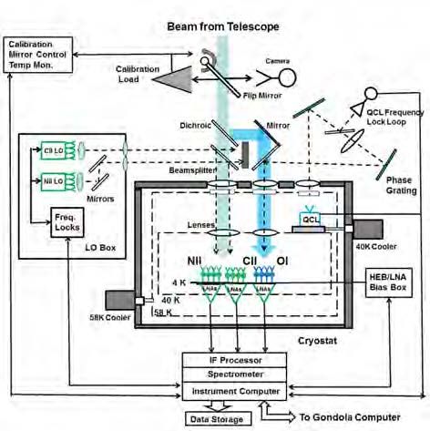
B. GUSTO instrument description
intermediate frequency (IF) bandwidth is still limited. So far,
HEBs have been used in a wide range of astronomical The GUSTO instrument concept can be found in Fig. 1. The sky-
observatories in order to observe different lines of terahertz beam from the telescope is split into two beams using a
radiation [1]–[3]. The use of multi-pixel receivers instead of a dichroic. The first beam (transmitted) will keep the information
single pixel receiver improves the mapping speed of the for the 1.4 and 1.9 THz channel while the second beam
telescope significantly. Thus, heterodyne arrays at THz (reflected) will be used to detect the 4.7 THz line. The sky-
frequencies are now demanded for airborne (SOFIA), balloon beams are then reimaged onto 4x2 HEB mixer arrays, one for
borne (STO-2, GUSTO) or possible future satellite (Origin each channel, in the focal plane. The arrays for 1.4 and 1. 9 THz
space telescope, OST) THz observatories. are placed side by side and therefore image slightly offset parts
of the sky. The LO signals are folded into the arrays using
82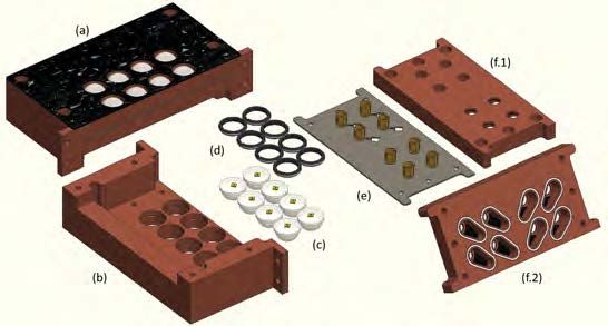
29th IEEE International Symposium on Space THz Technology (ISSTT2018), Pasadena, CA, USA, March 26-28, 2018

beamsplitters, one for 1.4/1.9 THz and one for 4.7 THz. After                     analysis of some of the key performance parameters within a
mixing, the output signal contains the same phase and                             batch of devices. The second is trade study of design parameters
frequency information as the original sky signal. The output                      of the Si lenses against performance.
signals from each pixel are amplified in individual cryogenic
                                                                                  A. Device performance statistics
LNA’s and then further processed in the warm IF and
spectrometer backend of the instrument.                                           In the device selection for GUSTO we aim for the highest
                                                                                  possible performance and uniformity while having some
                                                                                  flexibility. The selected HEBs, see Fig. 2 (a), are thin
                                                                                  superconductive bridges of NbN with 2×0.15 µm2 dimensions
                                                                                  between the pads of tight wound spiral antennas. Such a
                                                                                  combination has been shown to have good performance at 4.7
                                                                                  THz [6]. The use of a broadband spiral antenna allows for
                                                                                  flexibility since it is possible with a single design to populate
                                                                                  all the arrays.
                                                                                  For the device selection several fabrication batches were
                                                                                  studied and one preliminary was selected. From this batch, 10
                                                                                  different devices were randomly picked and characterized. The
                                                                                  measurements were performed in a vacuum setup at 2.5 THz
                                                                                  using AR coated lenses. The measurement setup is similar to
                                                                                  the one in [6]. The figures of merit for the evaluation were the
                                                                                  sensitivity (noise temperature), the LO power requirement and
                                                                                  the uniformity of these parameters among devices. The results
                                                                                  are presented in Fig. 2 (b) and (c). The average noise temperature
                                                                                  measured was 720 K with a 3% standard deviation. For the LO
                                                                                  power requirement an average of 227 nW was measured with a
                                                                                  standard deviation of 6%. The sensitivity measured reflects the
Fig. 1 GUSTO instrument block diagram, which was in the original proposal.
                                                                                  state of the art, and the LO power requirement is low enough
It is still in progress with regard to, in particular, the 4.7 THz LO.            that the expected next generation QCLs will be able to pump
                                                                                  the entire array (see next section). Moreover, the low deviation
In the past, other HEB arrays have been developed [4] but these                   found for both parameters, 3 and 6%, indicates the potential for
were designed with each pixel as a separate block. As GUSTO                       very uniform arrays.
will implement the highest pixel count so far and demands a
high level of integration, it requires a compact monolithic
design. In addition to the need for device performance
uniformity, both in sensitivity and LO requirement, it is also of
utter importance to ensure the correct pointing of the individual
pixels. Furthermore, because of the high integration level,
challenges regarding cross-talk have to be addressed.
Conceptually, each pixel will be used in a quasi-optical                          Fig. 2 a) SEM image of a tight wound spiral antenna HEB; B) Measured
configuration to couple the radiation from the sky and LO into                    Noise temperature distribution; c) Measured LO power distribution
the HEB, through the use of a lens-antenna system. Each device
will then be connected to a transmission line, at the end of                      B. Lens Study
which a connector will allow to extract the IF signal and supply                  At high frequencies (>2 THz), the manufacturability of good
dc-bias to the HEB.                                                               quality waveguide structures becomes difficult due to the
                                                                                  reduced size of the features. Therefore, the use of a quasi-
For the two lower frequency channels multiplier-chain based                       optical coupling becomes the best solution to obtain high
solid state LOs will be used. At 4.7 THz it requires the use of a                 sensitivity. In our quasi-optical system, we usually combine an
Quantum Cascade Laser (QCL) [5] as LO since this is the only                      extended 10 mm elliptical lens made of high purity Si with the
applicable solid state source with enough power at such a high                    spiral-antenna present on the HEB chip. While for a single pixel
frequency.                                                                        receiver the lens size is not a limitation, when converging to
In this paper, we will focus on the 4×2 HEB mixer array being                     arrays with high pixel count, the spatial footprint can become a
designed for the novel array receiver the 4.7 THz channel of                      problem. The most obvious solution for this is to simply reduce
GUSTO.                                                                            the lens diameter.
                                                                                  In this study two lens diameters, 5 and 3.1 mm, were compared
             II.    PERFORMANCE EVALUATION                                        with an existing 10 mm lens (see Fig. 3). These lens were
   Preliminarily to the array design we realized two                              designed as classical elliptical lenses as described in [7].
complementary studies where we evaluated/optimized the
future performance of the array. The first study is a statistical

                                                                             83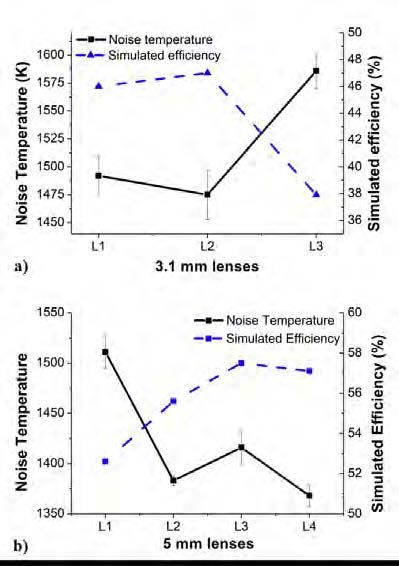
29th IEEE International Symposium on Space THz Technology (ISSTT2018), Pasadena, CA, USA, March 26-28, 2018

                                                                            etc). For the simulations we assumed the real lenses dimensions
                                                                            and tested different dielectric values, founding that the best
                                                                            value that matched our experimental results was 11.4
                                                                            confirming the previous conclusions. The curves for the
                                                                            simulated efficiency are plotted in blue in Fig. 4.

                Fig. 3. Si Lens used on the experiments.

The value of ξSi is one of the parameters required for the design.
In the past it has been thought this value at cryogenic
temperature to be the same as room temperature, 11.7.
However, more recently [8] it has been shown that the correct
value should be around 11.4. Since there is still some
uncertainty on this matter and we desire to optimize our system,
different lenses for each set were designed. For the 5 mm lens
we designed four different lenses L1, L2, L3 and L4, designed
for a ξSi of 11.2, 11.3, 11.4 and 11.5 respectively. In the case of
the 3.1 mm diameter we designed three lenses, L1, L2 and L3
designed for 11.2, 11.4 and 11.7 ξSi respectively. The real
parameters of these lens were measured and are summarized in
Table 1. In the 3.1 mm set we measured some relevant
variations on the lens dimensions compared to the design, while
for the 5 mm set the measurements matched the design.
Table 1. Measured lens parameters
     Diameter          Lens        Ellipticity         Extension
                                                      (incl. HEB)
     10 mm        L1                    1.0456                 1.582
     5 mm         L1                    1.0480                 0.783
                  L2                    1.0476                 0.779        Fig. 4. Noise temperature measurements and PILRAP efficiency simulations.
                  L3                    1.0468                 0.775                             a)3.1 mm lenses. b) 5 mm lenses.
                  L4                    1.0464                 0.772        Besides knowing which dielectric value should be used in the
     3.1mm        L1                    1.0458                 0.502        design process, it is also important to know what are the
                  L2                    1.0471                 0.498        tolerances acceptable in the fabrication. For the 3.1mm lenses
                  L3                    1.0477                 0.506
                                                                            we can see that a deviation on the extension of 5 µm can have a
                                                                            very big impact on the noise temperature (7%) increase while
To evaluate the lens performance we measured the noise                      for the 5 mm lenses the variation between L2 and L4 in
temperature using the same HEB-device for all the                           relationship to L3 is also 5 µm and we see a maximum absolute
measurements. Moreover, a misalignment no bigger than 5 µm                  difference from the best (L4) of 4% (L3). Therefore drawing
in a given direction was achieved, ensuring the performance                 the conclusion that the bigger the lens the more tolerant to
differences were due to the lenses only. The experimental setup             fabrication errors.
is similar to the one used in the device selection, only this time
we used an air setup and no AR coating. As baseline we                      In Fig. 5 we compare the best lens for each set in terms of noise
consider the noise temperature for the 10 mm lens, which best               temperature and the predicted lens efficiency for that specific
measured value was 1285 ± 25 K. The results for the noise                   lens. To avoid confusion it should be noticed that a perfect
temperature measurements for the other sets of lens can be seen             rescaling of the same lens design has the same lens efficiency.
in Fig. 4. For the 3.1 mm set the best noise temperature was                Looking at the noise temperature measurements we see a clear
measured for L2, with a value of 1447 ± 5 K, while for the 5                trend where the noise temperature increases as the diameter is
mm lens we measured 1368 ± 11 K for L4, although L2 show                    reduced. On the other hand the predicted efficiency doesn’t
very similar values. Moreover L3 in the 5 mm set seems to be a              match this behavior and seems to be decoupled from the lens
clear outlier. For both these set of lenses the best noise                  diameter in study. Based on this, and because there is a clear
temperature is found for designs assuming a ξSi close to 11.4 as            difference on the noise temperature between sets, some other
expected. However, since we had some variations in the                      effect must be in play. When studying what is affected by the
fabricated lenses, these could shift the real performance of the            rescaling of lenses it was found the lens diameter affects the
lenses. Therefore, each lens was simulated in PILRAP, a lens                beam pattern. The smaller the lens the wider the beam pattern
antenna simulation tool for the submillimeter range, using the              becomes. A hypothesis is that the noise temperature increase
real lens dimensions. From this tool we used as figure of merit             might have to do with the side lobes coupling improperly to the
the lens efficiency which is defined as the product of the                  calibration loads (e.g. the side lobes are always looking at a cold
multiple efficiencies within the lens (e.g. spillover, aperture,

                                                                       84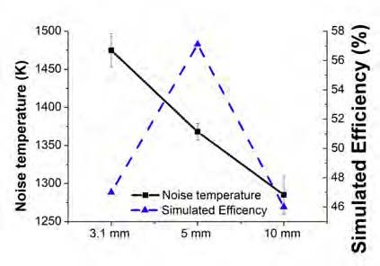
29th IEEE International Symposium on Space THz Technology (ISSTT2018), Pasadena, CA, USA, March 26-28, 2018

or hot load). Therefore, for the smaller diameter, we should see
the widest beam pattern and worse performance, matching the
measurements. Further measurements should be performed
minimizing the poor coupling of side lobes in order to verify
this hypothesis.

                                                                                  Fig. 6 GUSTO 4x2 HEB mixer array mechanical design

                                                                                  The copper piece identified as (a-front, b-back) in Fig. 6 is the
                                                                                  array housing. It is the core structure of the array and defines
   Fig. 5 Comparison of the best lens of each set and respective predicted        the placement of the pixels. It will be coated with a layer of
                                efficiency.                                       stycast mixed with SiC grains to reduce reflections. In this piece
Since we aim to implement eight pixel arrays, a relative low                      eight 10 mm Si lenses (c) will be placed with pre-aligned HEB
count, and the smaller lens diameter needs further study, due to                  chips and locked in place with retainer rings seen in (d). On the
the timeline it is chosen to fly 10 m lens as baseline. This choice               back of the lenses and covering them, a common PCB (e) is
reduces the risk for the mission since this diameter yielded the                  placed having eight independent co-planar waveguide (CPW)
best performance from the different sets studied, and will allow                  transmission lines and respective connectors. The devices will
to keep the relative fabrication error at the lowest possible.                    be connected to the CPW lines using bond wires. On top of the
Furthermore this size has been flown previously in STO-2, with                    PCB another copper part (f.1-back, f.2-front) will be placed
good flight performance. Moreover, based on our results, we                       with the function to isolate each pixel electrically and optically.
will assume 11.4 ξSi for the baseline design.                                     For this a spiral shield ring will be used (white in f.2) around
                                                                                  the area of each CPW to create a faraday cage that avoids
                                                                                  radiation to leak into adjacent pixels. In this same piece 8
         III.     THE 4×2 HEB MIXER ARRAY DESIGN                                  stycast/SiC layers (black material in f.2) will be put to absorb
The mixer array is designed as an eight pixel array in a 4×2                      any radiation that is not directly coupled into the HEB, reducing
configuration. The 4.7 THz HEB array is going to share the                        the potential for optical cross-talk in the array.
same architecture with the other two lower frequency arrays in
                                                                                                         IV.       SUMMARY
order to reduce the development time.
                                                                                  In this paper we have summarized the preliminary design study
The preliminary array design can be seen in Fig. 6 (a) represents                 for the 4×2 HEB array receiver being developed for GUSTO.
the fully assembled array as it will be placed on the cold plate.                 We discussed the study regarding HEB device performance
The main requirements determining the design are as follow: 1)                    statistics which yielded state of the art sensitivity of 720 K at
4×2 pixel configuration; 2) 10 mm diameter Si lenses; 3) 12 mm                    2.5 THz, low LO power requirement of 227 nW and very good
pitch size between each individual pixel; 4) side by side                         uniformity of 3 and 6% standard deviation respectively, thus
placement of the two lower frequency channels while                               matching the requirements for the array performance.
maintaining the pitch size, emulating a 4x4 array; 5) optical and                 Furthermore a lens optimization study was conducted from
IF path as similar as possible for all the pixels. 6) minimized                   which we concluded to choose to fly 10 mm lens instead of
optical and electrical crosstalk. 7) mechanical stability.                        smaller diameter lenses. These lenses showed the best
                                                                                  performance from the set of lenses measured and are expected
                                                                                  to the most tolerant to fabrication deviations. Moreover the
                                                                                  smaller diameter lens needs more research before being
                                                                                  properly understood. Furthermore, the experimental data
                                                                                  indicates the correct ξSi at cryogenics to be 11.4.
                                                                                  For the 4x2 HEB mixer array we introduced the mechanical
                                                                                  design required to support 8 pixels in a 4 by 2 configuration and
                                                                                  with a 12 mm pitch size. It will use a quasi-optical configuration
                                                                                  with the pre-selected 10 mm elliptical Si lenses.

                                                                                                        ACKNOWLEDGMENT

                                                                             85
29th IEEE International Symposium on Space THz Technology (ISSTT2018), Pasadena, CA, USA, March 26-28, 2018
We would like to thank Willem Jellema and Brian Jackson for
their help regarding the PILRAP simulations. The first author
would also like to thank Floris Van der Tak for his support and
guidance. This publication has received funding from the
European Union’s Horizon 2020 research and innovation
program under grant agreement No 730562 [RadioNet].
REFERENCES
[1] C. Walker et al., “The Stratospheric Terahertz
Observatory (STO),” in Proc. 19th International
Symposium on Space Terahertz Technology, pp. 28–32,
2008.
[2] S. Cherednichenko, V. Drakinskiy, T. Berg, P.
Khosropanah, and E. Kollberg, “Hot-electron
bolometer terahertz mixers for the Herschel Space
Observatory.,” Rev. Sci. Instrum., vol. 79, no. 34501,
2008.
[3] S. Heyminck, U. U. Graf, R. Güsten, J. Stutzki, H. W.
Hübers, and P. Hartogh, “GREAT: the SOFIA high-
frequency heterodyne instrument,” Astron. Astrophys.,
vol. 542, no. L1, pp. 1–7, 2012.
[4] C. Risacher et al., “First Supra-THz Heterodyne Array
Receivers for Astronomy with the SOFIA
Observatory,” IEEE Trans. Terahertz Sci. Technol.,
vol. 6, no. 2, pp. 199–211, 2016.
[5] B. S. Williams, “Terahertz quantum-cascade lasers,”
Nat. Photonics, vol. 1, pp. 517–525, 2007.
[6] D. J. Hayton et al., “A 4.7 THz Heterodyne Receiver
for a Balloon Borne Telescope,” in Proc. SPIE ,
Millimeter, Submillimeter, and Far-Infrared Detectors
and Instrumentation of Astronomy VII, vol. 91531R,
2014.
[7] D. F. Filipovic, S. S. Gearhart, and G. M. Rebeiz,
“Double-Slot Antennas on Extended Hemispherical
and Elliptical Silicon Dielectric Lenses,” IEEE Trans.
Microw. Theory Tech., vol. 41, no. 10, pp. 1738–1749,
1993.
[8] W. Zhang et al., “Optimized sensitivity and beam
pattern of a twin-slot antenna coupled NbN HEB mixer
at 1 . 6THz,” in Proc. of SPIE, vol. 8452, pp. 1–7, 2012,
86You can also read