FLIGHT PATH CONTROL ANALYSIS FOR PARKER SOLAR PROBE
←
→
Page content transcription
If your browser does not render page correctly, please read the page content below
AAS 17-631

                       FLIGHT PATH CONTROL ANALYSIS FOR
                              PARKER SOLAR PROBE

       Powtawche N. Valerino∗, Paul Thompson†, Drew Jones‡, Troy Goodson‡,
                       Min-Kun Chung‡, and Neil Mottinger‡

                An unprecedented NASA mission to study the Sun, known as Parker Solar Probe
                (PSP), is under development. The primary objective of the PSP mission is to gather
                new data within 10 solar radii of the Sun’s center. The purpose of this paper is to
                review the statistical analysis of trajectory correction maneuvers (TCMs) for PSP’s
                baseline trajectory. The baseline mission includes a total of 42 TCMs that will be
                accomplished with a monopropellant propulsion system that consists of twelve
                4.4 N thrusters. Assuming current navigation models, statistical analyses for each
                reference trajectory during the 20-day launch period result in a total ∆V99 of less
                than 100 m/s.

    INTRODUCTION
       The countdown to launch of the pathbreaking NASA Parker Solar Probe (PSP) to the Sun is
    currently underway. For almost 50 years, several heliophysics missions have studied our closest star
    and have provided a glimpse of the solar environment and its effects on the solar system. Formally
    known as Solar Probe Plus, PSP was renamed after astrophysicist Eugene Parker in May 2017.1
    Parker’s pioneering work theorized dynamical models of solar wind that were confirmed by data
    gained from satellite observations.2, 3 PSP will launch on a Delta-IV Heavy launch vehicle as early
    as July 31, 2018 and within a 20-day launch period.
       The PSP mission science objectives, coupled with innovative hardware, aim to better characterize
    the Sun. The probe will become the first spacecraft to fly by the Sun at 9.86 solar radii (RS ) or 6.8
    million km after a 6.4-year ballistic journey. In comparison, the Helios II spacecraft flew by the Sun
    at about 43.5 million km in 1975. The spacecraft will also become the fastest satellite at closest ap-
    proach of just under a speed of 200 km/sec (447,000 mph). PSP includes a suite of four instruments:
    Fields Experiment (FIELDS), Integrated Science Investigation of the Sun (ISIS), Wide-field Imager
    for Solar PRobe (WISPR), and Solar Winds Electrons Alphas and Protons (SWEAP), as shown in
    Figure 1. This science payload will work together to collect data related to solar wind electrons,
    magnetic fields, and waves, and will examine the following science goals:4

       • Trace the flow of energy that heats the corona,

       • Determine the mechanisms that accelerate and transport energetic particles,
∗
  Corresponding Author. Email: Powtawche.Valerino@jpl.nasa.gov; Address: Jet Propulsion Laboratory, California Insti-
  tute of Technology, 4800 Oak Grove Drive, Pasadena, CA 91109.
†
  Parker Solar Probe Navigation Team Lead, Jet Propulsion Laboratory, California Institute of Technology.
‡
  Navigation Engineer, Jet Propulsion Laboratory, California Institute of Technology.

                                                          1
• Explore dust plasma near Sun, and

   • Determine structure and dynamics of magnetic fields at the sources of solar wind.

        Figure 1. Parker Solar Probe and science payload (FIELDS, ISIS, WISPR, and
        SWEAP), Ram Facing View5

  Currently in Phase D, the PSP project is led by the Johns Hopkins Applied Physics Laboratory
(APL). While the mission design and spacecraft construction is managed by APL, navigation of the
spacecraft is supported by the Jet Propulsion Laboratory (JPL). The navigation team will provide
predictions of the spacecraft trajectory, work with mission design to plan and generate the trajectory
correction maneuvers (TCMs), and release the final reconstructed spacecraft ephemeris.
   Recently published papers give an overview of the mission design and navigation, as well as
challenges associated with each.6–8 The objective of this paper is to review the statistical analy-
sis of TCMs for PSP’s baseline trajectory with inputs provided by accompanying navigation and
covariance anaylses made during the Preliminary Mission Analysis (PMA).9, 10 Several cycles of
TCM analysis have been conducted; however, this is the first published paper that captures TCM
statistical results. Studies have been made to determine the mission’s total statistical ∆V, the cost
of missing or cancelling a scheduled maneuver, and the sensitivity of TCM placement. Finally, this
paper will point out the TCMs that are most important to execute based on the current navigation
models and mission assumptions.

SPACECRAFT OVERVIEW

   PSP is a solar-powered, three-axis stabilized spacecraft consisting of a Thermal Protection Sys-
tem (TPS) made of carbon composite that is 2.3 meters in diameter. The TPS will always be pointed
at the Sun (Figure 2) to protect the spacecraft bus from extreme temperatures. All of the science
instruments will be covered by the TPS, with the exception of the 4 antennas that are part of the
FIELDS experiment. Given a solar distance, the primary and secondary solar arrays will rotate to a
particular flap angle.11 Comprised of photovoltaic arrays, the primary array will be used outside of

                                                  2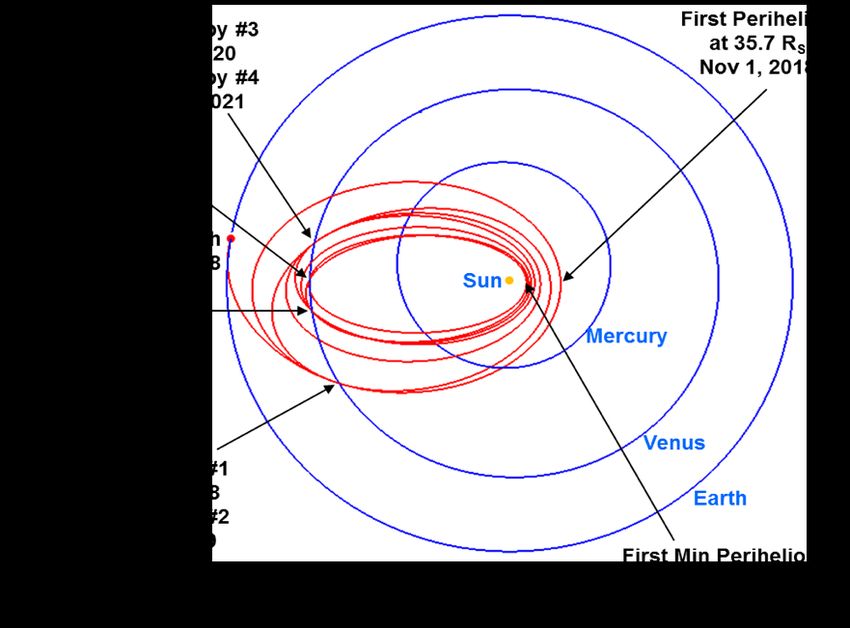
0.24 AU, and the secondary array will be used inside 0.24 AU, through closest approach. Since tem-
peratures are expected to reach more than 2,500◦ F (1,370◦ C), the secondary array utilizes pumped-
fluid coolant. Science downlink and communication will be made with the 0.6 meter Ka-band High
Gain Antenna (HGA). Maneuvers will be accomplished with a monopropellant propulsion system
that consists of a hydrazine tank and twelve 4.4 N thrusters.

                            (a) PSP near Earth                          (b) PSP near Sun

                       Figure 2. Spacecraft configurations near Earth and Sun

BASELINE TRAJECTORY
   The baseline trajectory, designed by APL, accommodates a 20-day launch period that starts on
July 31, 2018, and continues through August 19, 2018. The 6.4-year trajectory to the Sun uses
seven gravity assists of Venus (Figure 3). PSP will achieve three to four solar encounters per year
for a total of 24 solar encounters during the course of the mission. After the final Venus flyby,
the spacecraft’s perihelion distance will be reduced from 36 RS to 9.86 RS . A backup trajectory
is designed for a launch in 2019 and is based on shifting the baseline trajectory by one year. The
backup design utilizes eight Venus flybys to approach the final perihelion target.

                        Figure 3. PSP’s Baseline V7 -Gravity Assist Trajectory
  While the baseline trajectory is ballistic and has no deep space or deterministic maneuvers, careful
placement of the mission’s statistical trajectory correction maneuvers (TCMs) is made to correct

                                                  3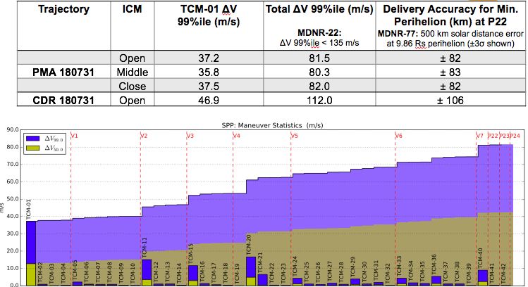
Venus flyby errors and other unmodeled errors. To control the spacecraft, TCMs are scheduled in the
following manner: two TCMs post-launch, two TCMs pre-Venus encounter, one TCM post-Venus
encounter, and at least one TCM per solar revolution, if possible. The cleanup TCM is scheduled
13 days or more after each flyby. A trajectory requirement mandates that one TCM targets solar
periapsis after the final Venus flyby. The baseline mission includes a total of 42 TCMs as listed in
Table 1 along with the dates of all encounters.

          Table 1. TCM and Encounter Schedule for the 31 July 2018 Baseline Trajectory
       Maneuver/             Date           Time*          Maneuver/        Date         Time*
       Encounter                            (UTC)          Encounter                     (UTC)
       TCM-01          07-Aug-2018         10:00:00         Venus-5      11-Oct-2021    18:35:12
       TCM-02          19-Aug-2018         18:00:00        TCM-24        06-Dec-2021    18:00:00
       TCM-03          07-Sep-2018         18:00:00        TCM-25        07-Mar-2022    18:00:00
       TCM-04          23-Sep-2018         18:00:00        TCM-26        16-Jun-2022    18:00:00
        Venus-1        28-Sep-2018         17:32:15        TCM-27        15-Sep-2022    18:00:00
       TCM-05          11-Oct-2018         18:00:00        TCM-28        17-Nov-2022    18:00:00
       TCM-06          05-Dec-2018         18:00:00        TCM-29        02-Apr-2023    18:00:00
       TCM-07          12-May-2019         18:00:00        TCM-30        02-Jun-2023    18:00:00
       TCM-08          06-Oct-2019         18:00:00        TCM-31         29-Jul-2023   18:00:00
       TCM-09          03-Dec-2019         18:00:00        TCM-32        11-Aug-2023    18:00:00
       TCM-10          16-Dec-2019         18:00:00         Venus-6      16-Aug-2023    21:04:02
        Venus-2        22-Dec-2019         3:01:40         TCM-33        09-Oct-2023    18:00:00
       TCM-11          05-Jan-2020         18:00:00        TCM-34        29-Nov-2023    18:00:00
       TCM-12          05-Mar-2020         18:00:00        TCM-35        10-Apr-2024    18:00:00
       TCM-13          18-Jun-2020         18:00:00        TCM-36        11-Jun-2024    18:00:00
       TCM-14           01-Jul-2020        18:00:00        TCM-37        21-Aug-2024    18:00:00
        Venus-3         06-Jul-2020        12:32:13        TCM-38        15-Oct-2024    18:00:00
       TCM-15           16-Jul-2020        18:00:00        TCM-39        27-Oct-2024    18:00:00
       TCM-16          23-Dec-2020         18:00:00         Venus-7      02-Nov-2024    4:27:22
       TCM-17          26-Jan-2021         18:00:00        TCM-40        20-Nov-2024    18:00:00
       TCM-18          11-Feb-2021         18:00:00       Periapsis-22   19-Dec-2024    20:02:27
        Venus-4        16-Feb-2021         5:14:03         TCM-41        27-Jan-2025    18:00:00
       TCM-19          02-Mar-2021         18:00:00       Periapsis-23   18-Mar-2025    6:43:41
       TCM-20          10-May-2021         18:00:00        TCM-42        16-Apr-2025    18:00:00
       TCM-21          20-Aug-2021         18:00:00       Periapsis-24   14-Jun-2025    17:24:15
       TCM-22          23-Sep-2021         18:00:00
       TCM-23          06-Oct-2021         18:00:00
       * TCM times are not yet finalized and subject to change.

REQUIREMENTS

   Forty mission design and navigation requirements (MDNR)12 were derived from the Level 2
Mission Requirements Document, and cite conditions that must be met during the mission. The
following outlines seven flight path control-related requirements:

                                                         4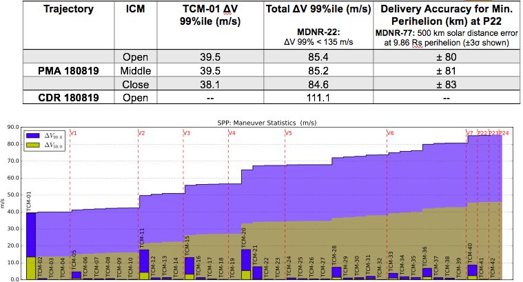
• MDNR-3: The spacecraft shall not spend less than 920 hours below 20 RS and 14 hours
below 10 RS,
• MDNR-22: The baseline total TCM ∆V99 can not exceed 135 m/s,
• MDNR-69: Adhere to TCM pointing constraints,
• MDNR-70: Adhere to constraints for TCMs at solar distance ≥ 0.45 AU,
• MDNR-71: There can be no consecutive burns more than 20 hours apart,
• MDNR-72: Each TCM burn can be no longer than 5200 seconds, and
• MDNR-77: Navigation Delivery Accuracy for Minimum Perihelion Delivery shall be within
500 km (3-σ) at 9.86 RS perihelion.
These requirements were imposed on the TCM analysis as constraints for part of the simulation
set-up. Additional navigation constraints correspond to the trajectory optimization strategy, such
as all Venus flybys can be no lower than 300 km. Also, maneuvers cannot be scheduled inside
0.45 AU from the Sun, and maneuvers outside 0.82 AU are implemented with 45 degree Sun-∆V
angle constraint (i.e.“cone keep-out”). Past mission design and navigation reviews confirmed that
all items were met.13 Other challenges PSP will encounter include interruptions of communications
and tracking of the spacecraft due to the significant occurrences of solar conjunctions as a result of
the trajectory’s highly elliptical orbits.
TARGETING STRATEGY
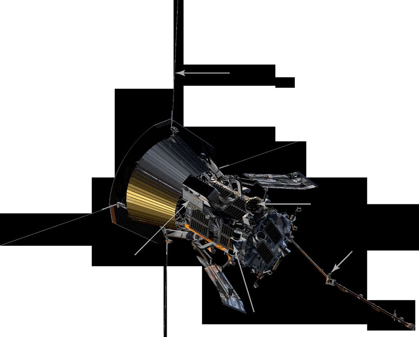
The targeting strategy shown in Figure 4 was employed for the trajectory simulation. This op-
timization strategy was chosen so that downstream maneuvers were used in a “chain” to target the
upcoming Venus encounter to minimize propellant and satisfy constraints. The x-axis represents
the maneuvers used in the optimization chain for a particular TCM, and the y-axis denotes the cor-
responding TCM. Each of the seven Venus encounters and final three perihelion are represented as
vertical lines. Note that the last two maneuvers before an encounter are constrained to the same
target. This increases the chance of cancelling the last TCM. Downstream TCMs within the chain
are re-optimized after each TCM is executed. The last three maneuvers (TCMs 40, 41, and 42) only
target perihelion distance, not position.
MATCH TRAJECTORIES
For all trajectory design cycles, the APL mission design team generates and delivers baseline
reference trajectories to the PSP project. The results in this paper reflect the most recent trajectory
design cycle, the Preliminary Mission Analysis. During PMA, mission designers delivered 20 ref-
erence trajectories that cover the July 31, 2018 to Aug 19, 2018 daily launch period, along with the
corresponding TCM and targeted flyby locations. The navigation team reintegrates or “matches”
these trajectories by targeting to three B-plane parameters14 of each encounter; the spatial compo-
nents B·R, B·T, and the time of closest approach for Venus periapsis (Venus-1 to Venus-7); time
for solar periapsis (Periapsis-1 to Periapsis-21, except Periapsis-10 and Periapsis-17); and periapsis
position for the last three solar periapses (Periapsis-22 to Periapsis-24).
5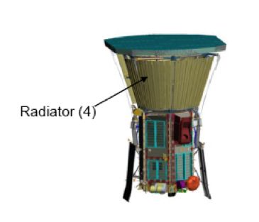
Figure 4. Targeting Strategy in MONTE-LAMBIC

   As expected, navigation results show small ∆V values (average TCM ∆V size less than 0.1 m/s)
for each of the trajectories to match the APL reference trajectories, and that the total ∆V differences
range from 4.0 to 5.5 m/s. These ∆V differences are a result of each’s teams own software and
integration schemes, and are an acceptable deterministic cost in the overall ∆V budget. The second
column of Table 5 lists the match ∆V differences for each day during the launch period.
   Figure 5 compares the position and velocity differences between the mission design reference
trajectories and navigation match trajectories for the open (31 July 2018), middle (10 August 2018),
and close (19 August 2018) of the launch period. The plots show that the approach TCM ∆V to each
Venus target is zero. Also, there is no ∆V difference at post-Venus-7 periapsis, and this satisfies
the PSP trajectory requirement for one TCM to achieve the 9.86 Rs periapsis distance after the final
Venus flyby. There are minor position differences at most of the solar periapses, except after the
Venus-6 flyby. The large post Venus-6 position difference is due to not targeting Periapsis-17 since
there is no TCM placed between the Venus flyby and solar periapsis.

RESULTS

   Assuming current navigation models, launch vehicle injection covariance matrices, an unscaled
figure-of-merit∗ , and maneuver strategy, statistical analyses for each reference trajectory during the
20-day launch period were conducted. A single Gates execution-error model,15 shown in Table 3,
was implemented to represent maneuver execution errors. These errors account for four independent
   ∗
    A figure-of-merit (FOM) is a parameter used to approximate the size of the first TCM given the capability of the
launch vehicle.

                                                         6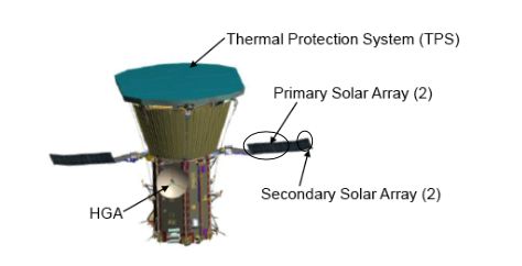
180731

                                                                                    4 / 23
                          (a) Differences for the open baseline trajectory.
180819

                                                                                   23 / 23
                          (b) Differences for the close baseline trajectory.

 Figure 5. Trajectory differences between mission design and navigation for PMA.
 Each dotted vertical line represents one of the seven Venus flybys.

                                           7
Table 2. PMA Match ∆V and Statistics
PMA Reference Total Match ICM TCM-01 ∆V Total ∆V
Trajectory ∆V(m/s) 99%ile (m/s) 99%ile (m/s)
– Open 37.2 81.5
31 July 2018 4.3 Middle 35.8 80.3
– Close 37.5 82.0
01 Aug 2018 4.4 Middle 37.9 80.5
02 Aug 2018 4.4 Middle 37.9 80.5
03 Aug 2018 5.0 Middle 37.5 81.9
04 Aug 2018 4.3 Middle 38.1 83.7
05 Aug 2018 4.3 Middle 37.1 82.3
06 Aug 2018 4.7 Middle 37.1 79.3
07 Aug 2018 4.8 Middle 37.3 81.4
08 Aug 2018 4.9 Middle 38.2 82.3
09 Aug 2018 4.9 Middle 38.0 83.7
– Open 38.6 86.9
10 Aug 2018 4.9 Middle 38.1 85.2
– Close 38.0 84.4
11 Aug 2018 5.0 Middle 40.0 84.0
12 Aug 2018 5.1 Middle 37.8 85.0
13 Aug 2018 5.2 Middle 39.4 82.6
14 Aug 2018 5.2 Middle 37.4 79.8
15 Aug 2018 5.5 Middle 37.8 83.7
16 Aug 2018 5.3 Middle 39.0 82.8
17 Aug 2018 4.5 Middle 38.4 89.4
18 Aug 2018 4.6 Middle 39.3 85.6
– Open 39.5 85.4
19 Aug 2018 4.4 Middle 39.5 85.1
– Close 38.1 84.6
error sources: fixed-and proportional magnitude errors, and fixed- and proportional-pointing errors.
The Mission-analysis Operations and Navigation Toolkit Environment (MONTE)16 Linear Analysis
of Maneuvers with Bounds and Inequality Constraints (LAMBIC)17 software was used to compute
statistical ∆V via Monte Carlo analysis.
Table 2 lists the trajectory, corresponding total match ∆V, ICM, TCM-01 ∆V 99%ile, and total
TCM ∆V 99%ile. The nomenclature used to describe the trajectories For the open (31 July 2018),
middle (10 August 2018), and close (19 August 2018) trajectories within the launch period, three
ICMs were provided for that day’s launch window. Note that when using the open or close ICM,
the trajectory is the same as the one listed for middle. For all the trajectories, statistical results in
a TCM-01 ∆V 99%ile ≤ 40.0 m/s, and mission ∆V99 of less than 100 m/s (last two columns in
Table 2).
These statistical results satisfy requirement MDNR-22, that is, the total post-launch statistical
∆V to 99% confidence, is not to exceed 135 m/s. To satisfy the pointing constraint (MDNR-69),
TCM design required a cone angle constraint. As an example, TCM-9 (V2-18d, 3-Dec-2019) is
performed in two burns to satisfy the pointing constraint.
8Table 3. Guidance & Control Gates Maneuver Execution-Error Model (3-σ)
Magnitude Fixed (mm/s) 1.2
Proportional (%) 2
Pointing Fixed (mm/s) 3.2
(per axis) Proportional (mrad) 20
Figure 6 presents the individual and cumulative 50%ile and 99%ile ∆V for the for the open and
close trajectories. Each TCM statistical prediction is shown and offers a glimpse of which maneuver
contributes most to the overall ∆V total. As expected, most of the post-Venus maneuvers have the
largest components since these maneuver cleanup the previous Venus flyby errors. The figure also
shows that TCM-01 has the largest statistical value since these maneuvers cleanup errors associated
with launch.
Table 4 shows comparisons of the PMA statistical predictions with the previous design cycle
(Critical Design Review, or CDR) for the open, middle, and close trajectories. For each trajectory,
it was observed that the total 99%ile ∆V was at least 20 m/s less than the CDR result. Sensitivity
studies revealed that refined updates to the ICM and orbit determination assumptions led to the
reduced ∆V results.
Table 4. PMA and CDR ∆V and Delivery Accuracy Comparison. Middle trajectories for CDR 180809
were compared to PMA 180810 values due to available ICMs.
PMA Reference TCM-01 ∆V Total ∆V Delivery Accuracy for Min
Trajectory 99%ile (m/s) 99%ile (m/s) Perihelion (km) at Periapsis-22
CDR 31 July 2018 46.9 112.0 ±106
PMA 31 July 2018 37.2 81.5 ± 82
CDR 09 Aug 2018 – 119.3 –
PMA 10 Aug 2018 38.6 86.9 ± 83
CDR 19 Aug 2018 – 111.1 –
PMA 19 Aug 2018 39.5 85.4 ± 80
Additionally, TCM capability analysis was performed on all the PMA trajectories. TCM locations
relative to their tracking schedules were evaluated to decide whether a TCM should be moved. This
was done by assessing TCM target/∆V gradient magnitudes and angles between gradient vectors.
TCMs can be in poor locations due to tracking gaps, Sun-Earth-Probe constraints, or unfavorable
dynamics. For example, a TCM could have linearly dependent ∆V gradients, or the angles between
gradient vectors near 0 or 180 degrees. This trade confirmed similar results as previous studies and
determined that TCM-19 is not required. TCM-19 ∆V ≈ 0 m/s until TCM-19 is placed at Venus-4
+28 days, and has similar trajectory geometry for all trajectories.
This study also revealed that TCM-17 for the last 5 trajectories in the launch window (i.e. 15 Aug
2018 through 19 Aug 2018) is located in a tracking gap. TCM-18 is also inside the tracking gap for
the baseline close trajectory. Continued evaluation of these maneuvers will be included in the next
design cycle.
9(a) TCM Statistics for baseline open trajectory.
10
(b) TCM Statistics for baseline close trajectory.
Figure 6. TCM Statistics for PMACONCLUSIONS
This paper reviewed the statistical predictions for the TCMs with inputs provided by accompany-
ing navigation and orbit determination anaylses made during PMA. Several cycles of TCM analysis
have been conducted; however, this is the first paper that captures the TCM statistical results. As-
suming current navigation models, each reference trajectory during the 20-day launch period results
in a mission ∆V99 of less than 100 m/s. It was also determined that the navigation delivery ac-
curacy for minimum perihelion was satisfied. Past experience shows every delivered trajectory is
unique and TCM analysis and results can vary. An upcoming design cycle in October 2017 will
provide the opportunity to regenerate statistical predications for PSP’s baseline trajectory.
ACKNOWLEDGEMENTS
This work was carried out at the Jet Propulsion Laboratory, California Institute of Technology,
under a contract with the National Aeronautics and Space Administration. c 2017 California Insti-
tute of Technology. U.S. Government sponsorship acknowledged.
11REFERENCES
[1] “NASA Renames Solar Probe Mission to Honor Pioneering Physicist Eugene Parker,” https://
www.nasa.gov/feature/goddard/2017/nasa-renames-solar-probe-mission\
-to-honor-pioneering-physicist-eugene-parker. Accessed: 2017-07-24.
[2] E. Parker, “Dynamical Theory of the Solar Wind,” Space Science Reviews, Vol. 4, No. 5-6, 1965,
pp. 666–708.
[3] Physics and Chemistry in Space: Coronal Expansion and Solar Wind. Springer-Verlag GmbH, 1 ed.,
1972.
[4] “Parker Solar Probe Science Objectives,” http://parkersolarprobe.jhuapl.edu/
The-Mission/index.php#Science-Objectives. Accessed: 2017-07-24.
[5] “PSP Spacecraft Ram Facing View Instrument Description,” http://parkersolarprobe.
jhuapl.edu/index.php#spacecraft. Accessed: 2017-07-26.
[6] Y. Guo, “Solar Probe Plus: Mission Design Challenges and Trades,” Acta Astronautica, Vol. 67, No. 9-
10, 2010, pp. 1063–1072.
[7] Guo, Y., McAdams, Ozimek, M., and Shyong, W.J.,, “Solar Probe Plus Mission Design Overview
and Mission Profile,” 24th International Symposium on Space Flight Dynamics, Paper S6-2, Laurel,
Maryland, May 5-9, 2014.
[8] Jones, D.R., Goodson, T., Thompson, P., Valerino, P., and Williams, J., “Solar Probe Plus: Unique
Navigation Modeling Challenges,” 27th AAS/AIAA Space Flight Mechanics Meeting, San Antonio, TX,
February 5-9, 2016.
[9] Jones, D.R., Thompson, P., Valerino, P., Lau, E., Goodson, T., Chung, M.K., and Mottinger, N., “Orbit
Determination Covariance Analyses for the Parker Solar Probe Mission,” to appear in proceedings of
the 2017 AAS/AIAA Astrodynamics Specialists Conference, Paper AAS 17-576, Stevenson, WA, August
20-24, 2017.
[10] Thompson, P., “Parker Solar Probe Navigation: One Year From Launch,” to appear in proceedings of
the 2017 AAS/AIAA Astrodynamics Specialists Conference, Paper AAS-17-604, Stevenson, WA, August
20-24, 2017.
[11] S. W.-J. Guo, Y. and C. Scott, “Solar Radiation Pressure Modeling in Mission Design Software for Solar
Probe Plus,” SEG-13-004, Johns Hopkins University Applied Physics Laboratory, Laurel, MD, 2013.
[12] Y. Guo, “Solar Probe Plus (SPP) Level 3 Mission Design and Navigation Requirements Document
(MDNR),” Rev C, Internal document, Johns Hopkins University Applied Physics Laboratory, Laurel,
MD, 2016.
[13] T. Goodson et al., “Solar Probe Plus Navigation Plan,” Internal document, Jet Propulsion Laboratory,
Pasadena, CA, 2015.
[14] Kizner, W., “Method of Describing Miss Distances for Lunar and Interplanetary Trajectories,” JPL
External Publications 674, August 1959.
[15] Gates, C.R., “A Simplified Model of Midcourse Maneuver Execution Errors,” JPL Technical Report
32–504, October 15, 1963.
[16] Smith, J., Taber, W., Drain, T., Evans, S., Evans, J., Guevara, M., Schulze, W., Sunseri, R., Wu, H.C.,
“MONTE Python for Deep Space Navigation,” Proceedings of the 15th Python in Science Conference
(S. Benthall and S. Rostrup, eds.), 2016, pp. 62 – 68.
[17] E. H. Maize, “Linear Statistical Analysis of Maneuver Optimization Strategies,” AAS/AIAA Astrody-
namics Conference, AAS Paper 87-486, Kalispell, Montana, August 1987.
12You can also read