HDD .Wait, No .Slipline! - TA-T5-02 North American Society for Trenchless Technology (NASTT) - Aegion
←
→
Page content transcription
If your browser does not render page correctly, please read the page content below
North American Society for Trenchless Technology (NASTT)
                                    NASTT’s 2019 No-Dig Show

                                                     Chicago, Illinois
                                                    March 17-20, 2019

                                                          TA-T5-02

                                        HDD….Wait, No….Slipline!

  Kerstin Kenty, Ph.D., P.E., PMP, ENV SP, Jacobs, Tampa, FL
  Dinesh Kamath, P.E., Pinellas County Utilities, Clearwater, FL
  Dennis Simpson, P.E., Pinellas County Utilities, Clearwater, FL

  ABSTRACT
  Pinellas County Utilities (PCU) had a major failure of a 30-inch ductile iron forcemain in 2017, prompting a
  condition survey. A 3,100-foot section of 42-inch ductile iron pipe (DIP) tying into the headworks of the water
  reclamation facility was discovered to be potentially at risk for a similar failure. In the last 35 years, the pipe
  corridor has gone from undeveloped land to a combination of two adjacent 10-foot easements and county-owned
  property traversing the backyards of upscale homes and a golf course at a championship resort. Lacking redundancy,
  PCU decided to install a redundant forcemain using horizontal directional drilling (HDD) in two sections (north and
  south).
  The north drill started first. Two days in, the driller was having difficulty returning drilling fluid, and shortly after a
  void opened on drill alignment. Due to time constraints, the only alternative was to open-cut install this section of
  pipe.
  The first attempt of the south drill progressed about 600 feet before fluid recirculation was lost and the drill was
  stopped. During the second attempt, there was no fluid return because the previous hole was acting as a conduit to
  the original void. Fearing another potential sinkhole in this karst-laden area, and not wanting to put the existing 42-
  inch pipe or the adjacent houses in danger, the driller abandoned the drill, removed the equipment, and demobilized.
  The north section of pipe had been installed previously so there is an option of bypassing the flow and sliplining the
  original pipe.

                                                            INTRODUCTION
                                                            Pinellas County, FL, located in west central Florida (Figure 1),
                                                            is the most densely populated county in the Tampa Bay area.
                                                            PCU provides service to more than 300,000 water customers
                                                            and treats 28.5 million gallons of wastewater daily at two
                                                            facilities. One facility, the W. E. Dunn Water Reclamation
                                                            Facility (WED WRF), is in the north-western area of the
                                                            county, and adjacent to the Innisbrook Golf Resort (Figure 2).
                                                            In 2016, PCU had a major failure in a 30-inch DIP forcemain,
                                                            which prompted a condition survey of other DIPs of similar
                                                            age. Survey results showed that a 42-inch DIP had trapped
                                                            gasses and was traversing homeowner backyards and the
                                                            Innisbrook golf course and tying into the headworks of the
                                                            WED WRF. PCU, concerned that a catastrophic failure could
                                                            be imminent, declared this an emergency project and
                                                            immediately began design activities to install a redundant
                                                            forcemain to allow a service outage in the 42-inch forcemain
Figure 1. Pinellas County Locator Map                     for rehabilitation.

                                                    Paper TA-T5-02 - 1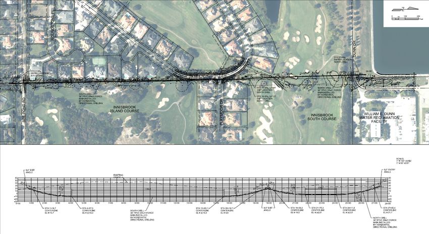
Figure 2. Project Locator Map
LOCATION
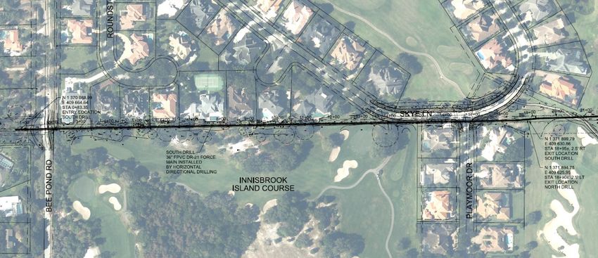
Stretching from Bee Pond Road on the south to the WED WRF on the north (Figure 2), the pipe corridor consisted
of a blend of two 10-foot easements (side by side) and county-owned property, which is leased to the Innisbrook
Golf Course. Figure 3 shows the location of the two 10-foot easements approximately 2,100 feet in length,
sandwiched between the Island course and upscale homes and containing a 36-inch reclaimed water line in addition
to the existing 42-inch DIP forcemain. The section on County owned land was approximately 1,000 feet in length,
with most of that land under lease to the Innisbrook Resort and in use for the South course. The tight easement did
not allow for an additional open-cut installation of the redundant forcemain. The decision was made to install a
replacement pipe using HDD as a single drill for the entire length because of the tight space, the crowded easement
which in some cases had swimming pools and decks within it, and the near impossibility of long-term bypassing due
to the need to traverse the working golf courses.
Paper TA-T5-02 - 2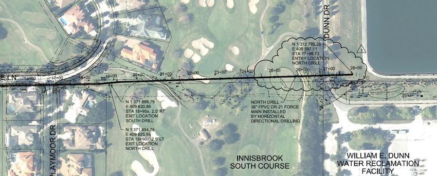
Figure 3. Ariel View of Easement and Pipe Alignment

PIPE
Concurrently, work had begun on a separate project to upgrade the headworks to the WED WRF upstream of the tie-
in for this pipe, and significant sediment had been found in the pipe as part of that project, suggesting it was
oversized. In a separate investigation, it was concluded to replace the existing 42-inch pipe with a 36-inch pipe.
Materials considered for the pipe were high density polyethylene (HDPE) and fusible poly ethyl vinyl chloride
(FPVC). Due to the subsurface conditions, and a smaller size option for FPVC pipe, FPVC was the preferred choice.
At each terminus, the new FPVC pipe would need to be tied in to the existing DIP.
The narrow easement traversed the backyards of many up-scale homes, was adjacent to one of Innisbrook’s golf
courses, and traversed an additional Innisbrook Resort golf course.
NEIGHBORS
Public involvement was important for this project given that large portions of the easement were within the
backyards of homes backing up to the golf courses. Figure 4 shows the easement nestled between the homes and the
golf course, with the easement sometimes located only inches off a homeowner’s pool deck. Work in the easements
would surely be noticed by the homeowners. In addition, the Innisbrook Resort hosted an annual Professional
Golfers' Association of America (PGA) tournament. While the tournament was not conducted on either of the
courses adjacent to this project, Innisbrook was very concerned with image during tournament week, and all courses
at the resort received additional traffic during that time. In addition, the golf courses needed to remain open during
the construction, and golf cart traffic had to be maintained for the golfers.

                                                Paper TA-T5-02 - 3
Figure 4. Drill Alignment Proximity to Neighboring Homes
At project inception, an integrated public information campaign was implemented that included public meetings for
the homeowners and one-on-one meetings and updates for the Innisbrook staff. Innisbrook’s groundskeeper was also
present onsite observing a lot of the day-to-day work, interfacing with the contractor directly. As the project
progressed and changed, homeowner public involvement evolved to include an information pop-up, door-to-door
communications, and a dedicated hotline for residents to reach out to the project team.
Throughout the project, the proactive and transparent communication strategy helped mitigate concerns and allowed
two-way communication on all issues related to the project.
GEOTECHNICAL CONSIDERATIONS AND DESIGN
In terms of geomorphic districts, the site is in the lower southwestern corner of the Ocala Karst District. The
occurrence of karst features varies from abundant and closely spaced to scattered in the area. The Ocala Karst
District is dominated by sinkholes and shallow bowl‐shaped depressions, producing a rolling topography. Generally,
downward percolating groundwater slowly dissolves the underlying limestone, leading to cover‐collapse sinkholes
and cover‐subsidence features. Cover‐collapse sinkholes form rather abruptly from the structural failure of an
underlying cavern roof, where cover subsidence features generally occur in areas where sediments sag as carbonates
dissolve underneath. Springs, sinks, sinking and resurgent streams, and caverns commonly occur within the Ocala
Karst District.
The geotechnical investigation revealed geology in the area consistent with the above description, leading to
alignment constraints for the HDD. Research conducted by Jacobs indicated that the golf course had been a former
site for land-application of treated wastewater and these activities had been noted to have resulted in several
collapses of underlying solution cavities. In addition, anecdotal descriptions of a sink hole that developed during
construction of improvements to the WED facility were provided by PCU staff. After standard penetration test
boring information suggested there could be a limestone pinnacle in the HDD pathway, a geophysical survey using
seismic methods was performed. This investigation revealed there were no limestone pinnacles in the HDD
pathway, and that there were some soft areas, believed to be older cover-subsidence features.
Another concern of the design team was that the limestone was relatively shallow along the alignment, which left
the team with two choices: drill deep into the karstic limestone or remain shallow (on the order of 30 to 50 feet
below existing grade) and avoid the voided structure of the limestone. The decision to plan a relatively shallow drill
for the long drill length presented a risk of drilling fluid coming to the surface under pressure during the drill. When
the drilling fluid pressure in the borehole exceeds the overburden pressure, inadvertent return of drilling fluid to the
surface, or frac‐out, can occur. Risk of frac‐out is high when the pilot bore is near the ground surface, particularly at
the exit point. The second issue was the presence of unconsolidated materials and past voids that had filled in along
the pipe corridor. With this in mind, the HDD was designed as a single drill, with a shallow entry angle on the north
end to maintain as much cover above the identified loose soil zone where evidence of historical voids existed. The
design team also planned and implemented requirements for relief wells and immediate spill cleanup teams that
could work in the confined back yard easement area.

                                                 Paper TA-T5-02 - 4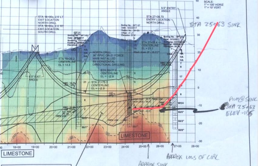
Taking all the above requirements and constraints into account, the initial design was provided as a single 3,100 feet
HDD with a maximum depth of 55 feet, due to the shallow limestone depth. This method was selected for its cost‐
effectiveness, relatively low risk of settlement, and ability to cross beneath the existing utilities, private
improvements, and the golf courses. Due to the emergency nature of the project, the general contractor was sole
sourced but three drillers were pre-qualified to provide pricing for the project.
During solicitations for pricing, the drillers expressed many of the same concerns that the design engineers had
identified, the karst geological nature of the area and the shallow limestone. The drillers felt the risk to do a single
3,100-foot HDD was too great at such a shallow depth due to the sandy soils and the potential for frac-out. The
drillers wanted to drill deeper, through the limestone. However, limestone near the project is considered highly
voided and unsuitable for HDD installation. Unsupported broken rock within the rock mass and within filled
collapse chambers introduces an additional risk of FPVC pipe damage during pullback and a stuck drill string during
pilot and reaming. The risk of fluid loss, steering difficulties, and the potential to encounter cobble‐sized rock
fragments was considered too great to design an HDD within the rock at this site.
To mitigate some of these concerns for the drillers, the project was redesigned into two shorter HDD drills, the
North drill, which was approximately 1,000 feet in length and the South drill, which was approximately 2,100 feet in
length, shown in Figure 5. Because the County owned the property on the northern end of the HDD, it was possible
to break the project into two HDD sections to be installed separately, and both pulled from the same pit in between
the two sections.

Figure 5. P-Wave Velocity Cross Section Data with Two-Drill Geotechnical Baseline Report Profile

Delineation between the North and South drills is shown in Figure 6 along with the stratigraphy defined in the
Geotechnical Baseline Report (GBR) (CH2M HILL Engineers, Inc., 2017). The maximum allowable drill fluid
pressure was calculated using the method of Bennett and Walin (2008) with the revised approach recommended by
Staheli, et al. (2010) (incorporating a factor of safety of 2.5). For the North drill, the lowest factor of safety (defined
as the ratio of the ultimate maximum frac‐out pressure to the predicted circulating pressure) was predicted to be 3.9,
approximately 600 feet from start of the drill.

                                                  Paper TA-T5-02 - 5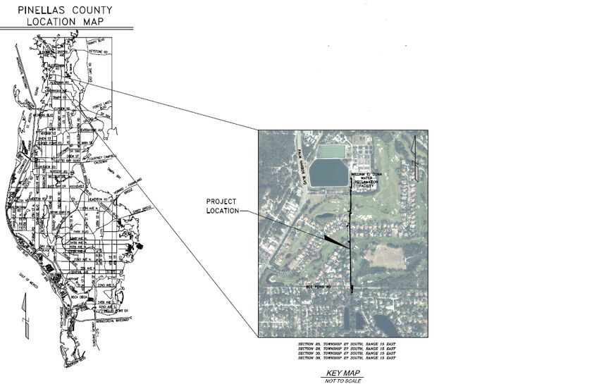
With two shorter drills, the drillers were more comfortable with the conditions and the mitigation of the frac-out
risk.

Figure 6. Two Drill Alignment on Aerial (top) with Profile (bottom)
CONSTRUCTION
North Drill
The contractor mobilized and began the north drill first in mid-September. The drill consisted of a run of
approximately 1,000 feet across the 12th hole of the Innisbroook South golf course. As noted in Figure 7, the launch
pit was stationed to the north end of the drill and the receiving pit was in a County roadway right-of-way just north
of Skye Lane. The entry point had been shifted slightly to the north at the contractor’s decision, to avoid the need to
protect a number of existing utilities.

                                                Paper TA-T5-02 - 6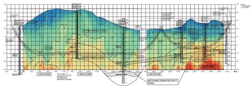
Figure 7. North Drill Alignment
Before commencement of the drill, an onsite meeting was held between the design engineer, the engineer’s HDD
expert, the contractor, the contractor’s guidance specialist, and the engineer’s onsite inspector for HDD. The
geological information included in the GBR was reviewed and the importance of not running the pilot too close to
the limestone was reiterated. Prior to the meeting the HDD contractor and guidance specialist were not aware of the
provision of a GBR.
Two days into drilling, the driller experienced difficulty in returning drilling fluid, and shortly after a void opened
on the tee box of the 12th hole of the Innisbrook South Course. At this time, drilling stopped. Upon review of the
guidance data, it became evident that the driller had chosen a deeper drill profile than specified with a bend radius
that did not meet design guidelines, as shown in Figure 8. Note in the figure that the hatched zone was specifically to
be avoided during drilling.

Figure 8. Two Drill Vertical Alignment with As-Drilled Pilot Profile and Field Notes
Discussions ensued with the engineer, the driller, the contractor, the golf course, and the County. Ultimately, it was
decided that changing the alignment was risky without an additional geotechnical investigation, and the driller was
not comfortable continuing the drill with the geotechnical conditions uncovered. The County was under a time
constraint for the project, both because of the need to get the new pipe into service proactively, as well as the need to
complete all work on the golf course before March 2018 when Innisbrook hosted the PGA Valspar Championship.
The only viable installation method left was to open-cut this section of pipe across the golf course.

                                                 Paper TA-T5-02 - 7
Throughout the project, the County and the general contractor had been communicating directly with the Innisbrook
Resort. When the open-cut option was considered, Innisbrook Resort was informed and consulted. Coincidentally,
the Innisbrook Resort was planning to shut down the South Course for 2 weeks in October, which opened a window
for the contractor to perform the open cut work.
The contractor set out to install nearly 1,000 feet of 36-inch FPVC, which had been fused in anticipation of the HDD
install within the 2-week shutdown window. The week before the golf course shut down was spent locating, looping,
and protecting the golf course irrigation system, as well as performing final locates and preparing the site to dig.
When the time came to install the pipe, the contractor began Monday morning and mobilized 3 crews working 12
hour shifts for 6 days to install the pipe. The execution was flawless, with separate excavation, backfill, and grading
crews onsite simultaneously. The weather was favorable, and the contractor put the final section of pipe in the
ground 4 days after starting, on Thursday evening of the first week, and by Friday was backfilling. The second week
included completing final grading and additional backfilling.
South Drill
Meanwhile, the south HDD still loomed. Hurricane Irma had disrupted operations, as the crew fusing the pipe was
based out of Boca Raton, FL. The fusing crew returned to the site and completed fusing the pipe concurrently with
the north open-cut installation. The driller remobilized to the site a week and a half after the north open-cut
installation was complete. As shown in Figure 9, the south drill launched from the southern side of Bee Pond Road
and exited in the same roadway right-of-way the north drill was planned to exit, just north of Skye Lane.

Figure 9. South Drill Alignment
The project schedule had been affected by the issues encountered during installation of the pipe at the North Drill,
both on the project site and for the driller. The driller mobilized as soon as possible and scheduled the drill to begin
on Saturday to maintain schedule. During this operation, the driller encountered conditions where drill fluid was not
being returned and was concerned that another sinkhole would be opened up, this time in the backyard of someone’s
home. The driller retracted the pilot drill to begin a new profile but encountered the same issues with drill fluid not
returning due to the hydraulic connection to the first drill path. As this continued, the driller became very nervous
another sinkhole was about to open, and again retrieved the equipment from the pilot drill and proceeded to pack up
and demobilize from the site on Saturday afternoon.
With the driller demobilized, when the team reconvened on Monday to troubleshoot solutions there weren’t many
options. The contractor communicated that his driller was very nervous drilling at the site and was not inclined to
complete the drill. Subject matter experts on the engineer’s side conveyed that with the driller removing the
equipment many of the mitigation options available were not viable, and it made continuing the drill on the south
side very difficult.
The contractor suggested that instead of using HDD to install the south section of pipe that it be installed via
slipline. Since during the design phase, modeling had indicated that the pipe be sized at 36 inches instead of the
original 42-inch pipe in the ground, the suggestion was to install the 36-inch FPVC pipe sliplining the original 42-

                                                 Paper TA-T5-02 - 8
inch DIP. This was an intriguing suggestion, and the contractor had done some preliminary work determining if the
FPVC pipe would fit inside of the DIP and had reached out to the FPVC pipe manufacturer, Underground Solutions,
to determine if the deflection angles were acceptable for the material.
Assuming materials allowed for a viable installation, installation via this method would require that a bypass be
installed, because the pipe being sliplined was still in operation. This was only available as a solution if the north
section of pipe, installed via open cut, had the connections completed, and was tested, and was able to be put into
use during the installation.
Southern Installation – Gopher Tortoises
Gopher tortoises are a State of Florida protected species, and they were found in the pipe staging area for the
southern installation during the design phase. Both the burrows and the animals are protected, because the burrow
can provide habitat for additional protected species. As per Florida Law, a gopher tortoise survey was completed
before construction commenced, and any gopher tortoises that encroached on the project site were removed and
relocated by a licensed Gopher Tortoise Agent. Due to the numerous stops and starts between the project
commencement and the slipline of the southern installation, gopher tortoises moved back into the project area. This
required additional survey, permitting and removal, and held the project up for about a week while it was resolved.
Southern Installation – Sliplining
Switching to a slipline required a coordinated effort between the engineer, owner, and contractor. The pipe
manufacturer was also consulted to verify that the installation was within the FPVC’s tolerances and was reasonable.
Since the original DIP was installed around 1972, the existing as-builts were consulted and any area that looked to
have a deflection that could exceed the pipe tolerance was excavated and visually examined. The plan was to
remove any areas of DIP where the deflection tolerances were not within the necessary limits to slipline the
alignment with FPVC. Additionally, the contractor dug a few potholes to verify elevations and ensure there weren’t
unknown deflections that could derail the installation.
During this investigation, the contractor worked on bypass options. There were a few different configurations that
would be sufficient to convey the flow in the existing 42-inch pipe, but the final result was dual HDPE pipes of 18
inches and 24 inches, with two road crossings that were to be handled with road plates. After the bypass line was put
into service, the road plates were clogged within a week, and the original pipe had to be put back into service while
the road crossings were redesigned and installed as temporary open-cut installations.
In addition to the bypass, another aspect of the project was the need to drain and clean the original pipe before
installation. This was unknown in the project, as, since put into service in 1972, it was not believed the pipe had
been cleaned, and knowing the pipe was oversized, there was concern for what would be found in the bottom of the
pipe. In the end, it took 6 weeks to clean approximately 2,000 feet of pipe.
Finally, it was time to perform the slipline install. It was done on a Saturday, with the HDD contractor using rod sets
to perform the pull. The installation was successfully completed without incident.
CONNECTION AND CLOSE OUT
After the installation of the pipe via slipline, the connections had to be performed, along with final testing, before
the line could be put into service. This was accomplished quickly, and the pipe went into service in August 2018.
Shortly after, the contractor began dismantling the bypass line and restoring the installation corridor to the original
conditions.
LESSONS LEARNED
This project started out as routine (except for the accelerated timeframe) and the HDD project anticipated to have
low visibility and minimal disruption to neighbors. Ultimately, installations required constant communication,
coordination, and cooperation. The key takeaway is the importance of a strong public outreach program, regardless
of the nature of the project. As the project shifted to open-cut across the golf course, the open dialogue that had been
started with Innisbrook was instrumental in moving that portion of the project forward. In the same way, Innisbrook
was helpful in providing temporary easement and access across their property to allow various parts of the project to
be completed.

                                                 Paper TA-T5-02 - 9
As the project progressed, the need for public outreach and involvement increased exponentially. Having the public
involvement team engaged from the beginning allowed them to answer questions and contribute meaningful
suggestions on how to create a dialogue with homeowners.
It will never be known whether the two drills could have been completed successfully with better coordination
between driller, guidance specialists, and the owner’s engineers. In the case of the north drill, the HDD contractor
ignored repeated warnings to avoid a loose subsurface zone that represented a historic cavity collapse. On the south
drill, the lack of onsite dialog and inability to provide supplemental equipment, such as a washover casing during
pilot advancement, left the team with little choice once the HDD contractor had unexpectedly demobilized over the
weekend. Likewise, the drilling contractors who bid on the project were vetted via a prequalification step for
experience with both the method and geological conditions. In theory, the driller should have had the requisite
experience to respond proactively to the geologic uncertainties. It is possible a more experienced, or more
aggressive, drilling contractor may have been less intimidated by the conditions on the second drill and not
immediately demobilized. With the known sinkhole potential in the area, and the cost of the loss of drilling fluid for
the contractor, it was a difficult situation for the contractor. Part of the take home of this project is that not every
unfortunate decision leads to a worse outcome. Ultimately, the driller’s hasty demobilization stopped what could
have been a lengthy, and increased risk, process to traverse that section of the drill to complete the project and
instead opened up the opportunity to re-evaluate the installation and implement a solution that is probably superior
to the original.
Another important lesson learned was the importance of cooperation and coordination between the owner,
contractor, and engineer. Traditionally, especially as a project progresses through the construction phase, these
relationships can become contentious. This contentious relationship did not evolve on this project because the
project team was responsive and supportive as challenges arose. Pinellas County was adamant that the culture of
their organization includes all partners working toward the same success. Examples of teamwork included the
upfront project bidding when the drillers were pricing the project based on their perceived risk and the engineer had
to complete a redesign. Later in the project, when the contractor had to switch to an open-cut installation, the
engineer had to get a plan and profile prepared in a very short time period and complete a site visit to confirm the
project could progress within the tight timeframe. The change of the project from a drill to a slipline on the South
drill was another instance when the trust relationship between the owner, contractor, and engineer was instrumental
in keeping the project moving forward. Likewise, this relationship was important when the gopher tortoises were
found in the FPVC lay down area and the contactor was at a complete standstill before the engineer’s team pulled
the permits and relocated the tortoises.
Finally, understanding that unforeseen challenges arise when construction begins regardless of the anticipated
delays, thoughtful preparation, and thorough due diligence is imperative. It is important to be engaged in the project
throughout, as a designer, to meaningfully contribute viable solutions when things don’t go as planned.
RECOMMENDATIONS AND CONCLUSIONS
This was a dynamic and challenging project but ultimately resulted in a successful installation with minimum
disruption to the adjacent homeowners and the operating golf course. Keeping the homeowners (via the
homeowner’s association) and the golf course (via management) informed as the project changed contributed to the
successful outcome of the project. Without the open working relationship with the golf course, there would have
never been agreement for the open cut work to proceed during their shut down. Without the open cut section
installed, a bypass solution would not have been possible.
All projects and teams face challenges. It is the way that the team comes together to handle the challenges that
ultimately determines project success. Even projects that are, from technical and physical environment standards,
installed correctly are rarely perceived as overly successful by the parties involved when the relationships devolve.
Also, when these relationships break down and communication stops, situations develop where it is difficult for the
owner or engineer to make the best decisions for the project. This project is a great example of contractor input
helping drive a successful solution. Technical expertise is always leveraged to obtain its best value when
communication between all parties is open. That is the formula to successfully address unforeseen challenges on a
project.
REFERENCES
Bennett, David, and Kathryn Walin. 2008. Step by Step Evaluation of Hydrofracture Risks for Horizontal
Directional Drilling Projects. Presented at the International Pipelines Conference 2008, Atlanta, Georgia, July 22-27.
Paper TA-T5-02 - 10CH2M HILL Engineers, Inc. (CH2M). 2017. P-Wave Velocity Cross Section Data with Two-Drill Geotechnical
Baseline Report Profile. August.
Staheli, Kimberlie, Price, C. G., Wetter, L. 2010. Effectiveness of Hydrofracture Hrediction
for HDD Design. Presented at the North American Society for Trenchless Technology (NASTT)
No-Dig Show 2010, Chicago, Illinois. May 2-7.
Paper TA-T5-02 - 11You can also read