High Density Polyethylene (HDPE) Lined Produced/Frac Flowback Water Evaporation Ponds
←
→
Page content transcription
If your browser does not render page correctly, please read the page content below
High Density Polyethylene
    (HDPE) Lined Produced/Frac
    Flowback Water Evaporation
              Ponds

1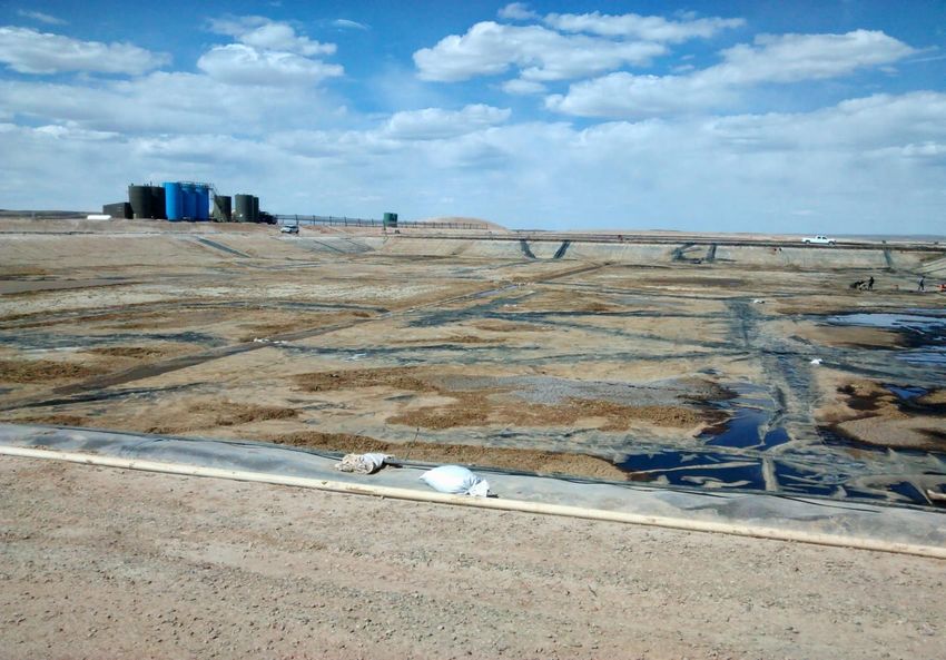
TOPIC OF PRESENTATION: Use of black High
Density Polyethylene (HDPE) as the top layer of
    brine (production) and flow back water
 evaporation pond facilities and the effects on
         evaporation rate. Case study.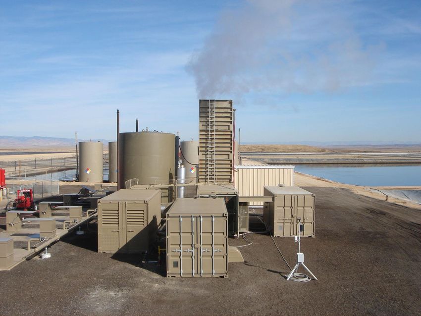
PURPOSE:
•   Dispose of production
    water and flow back
    water generated from oil
    and gas development.
•   Several million barrels
    of production water and
    flow back water are
    generated each year in
    many states.
•   Varies from 1/2 to 8 bbls
    of water produced per
    barrel of oil (depends on
    formation).
•   Other types of
    evaporation and disposal
    facilities exist.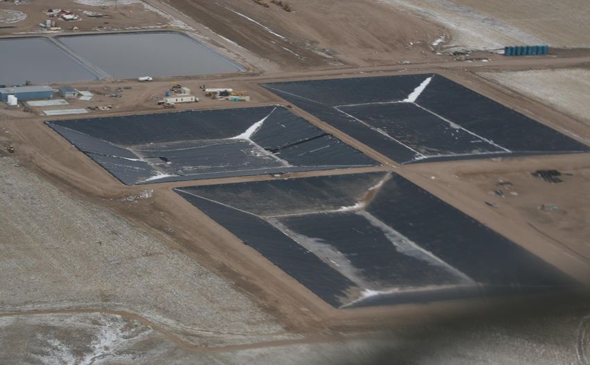
Oct. 2014
SELECTION OF TECHNOLOGY:

Technologies for managing production and
flow back water:
– Disposal injection into acceptable zone
– Recycle/reuse
– “Frac” injection of the water into the
  production formation to enhance yield
– Treatment for surface discharge
–Evaporation
HDPE Lined Evaporation Ponds
      Not Extinct Yet?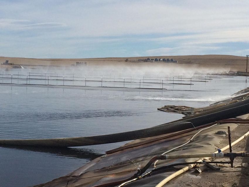
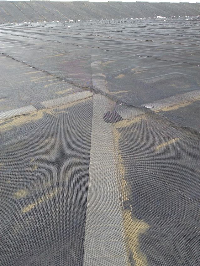
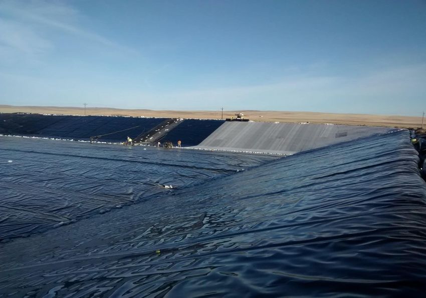
DESIGN…WHY HDPE?:
60-mil thick HDPE for top liner of ponds not buried.
• Ultraviolet (UV) degradation resistance.
• Durability (20 plus years, Ivy 2002); Koerner 2016
  stated 90 plus years (next slide).
• Chemical resistance.
• Black color enhances evaporation of water.
• HDPE was chosen over clay liner and other
  geomembranes due to being the most compatible with
  site conditions and regulations (i.e. exposed to sunlight,
  desiccation, and hydrocarbons).
• Textured surface used to aid with traction if operations
  personnel fall into ponds, and to increase slope friction
  and stability.
RESULTS OF FIVE GEOMEMBRANE FIELD HALFLIFE
PREDICTIONS IN PHOENIX, ARIZONA COMPARED TO
PREVIOUS LABORATORY PREDICTIONS AT 20°C
 Geomembranes         Thickness   Laboratory Predicted Half-   Phoenix, Arizona Predicted
 (Various Resins)       (mm)            life in Years              Half-life in Years

                                   Strength      Elongation      Strength     Elongation

 HDPE (60-mil)          1.5           76            69             97            91
 LLDPE                   1.0          49             46            66            63

 fPP                     1.0          50             41            59            54

 EPDM                    1.0          60             70            74            56

 PVC (Euro.)             2.5          54             54            72            55

 From Geo-Americas April 2016, Lifetime Predictions of Exposed Geotextiles and
 Geomembranes by Bob Koerner, Grace Hsuan and George Koerner at Geosynthetic
 Institute/Drexel University.
DESIGN:
High Density
Polyethylene (HDPE)
designed as the
primary or top layer of
the lined ponds in
order to protect the
groundwater and to
enhance the
evaporation of the
production water
within the ponds.
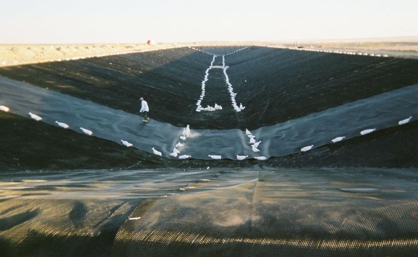
Geomembrane panels are welded together throughout the
installation performed by trained and certified technicians.
Geomembrane panels are tested for strength throughout
the installation performed by trained and certified
technicians.
Ponds designed and constructed with one or two
geomembranes over compacted clay or geosynthetic clay
liner and a geonet leak layer in between to monitor the
primary liner for leaks.
CONSTRUCTION
 Ponds designed
 and constructed
 with two
 geomembranes
 over compacted
 clay or
 geosynthetic clay
 liner and a geonet
 and flat pipe leak
 layer in between
 to monitor the
 primary liner for
 leaks.
Projects located in
semi-arid regions:

– Eastern Utah
  (Danish Flats) near
  Cisco
– North of Baggs, WY
  (Southern Cross)
– Cheyenne, WY (Silo
  Field)
– Northeast WY
  (Bluegrass Water at
  Wright)
Danish Flats Utah, 14 ponds at 5 acres each,
70 acres of lined ponds and capacity = 6.5
million barrels.
Southern Cross with five ponds at 5 acres each and
capacity = 2 million barrels operational (2014),
including enhanced evaporation sprayers.
Silo Field under construction (2010) 3 ponds at
5 acres each.
Wright Facility under construction 2016, includes
GCL, and double geomembrane with leak layer in
between.
Bluegrass Water Wright, WY - ponds at 9 acres area and 1
million barrels capacity each, including enhanced
evaporation sprayers. Currently Ponds #1 thru #6
operational = 6 million barrels total capacity.
Production
     water
delivered to
the sites via
    tanker
  trucks for
disposal by
evaporation
Truck receiving area/off-loading via hose and pipeline to initial phase separation in gun-barrel tanks.
At Danish Flats, off-gases from acceptance pits and gun barrel tanks
are routed to a control device, which includes a thermal oxidizer and
scrubber.
From gun-barrel tanks the
water goes to
HDPE lined
settlement/sludge pond
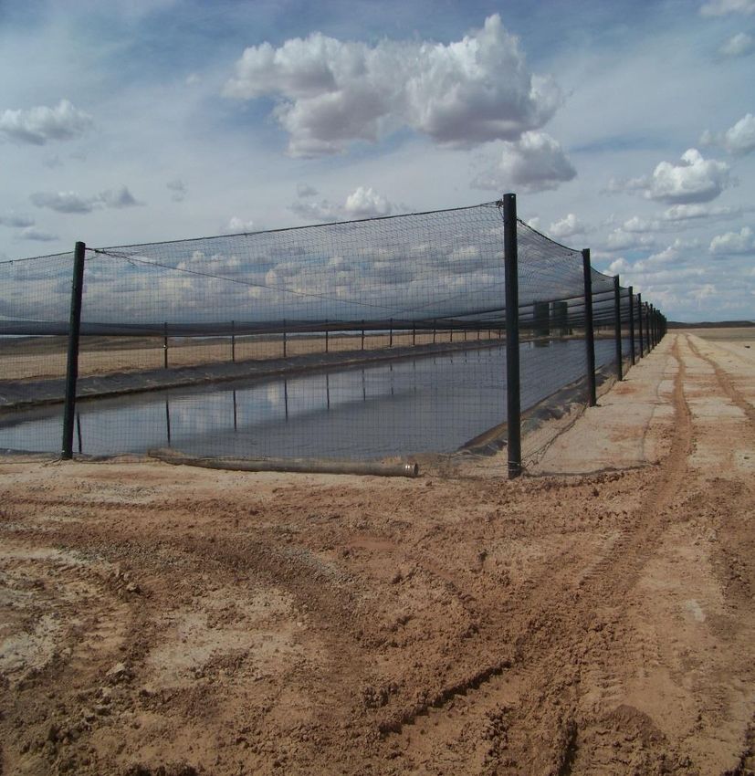
Last stage of hydrocarbon
removal and collection that
requires bird-netting to cover
the water, which will likely
have floating hydrocarbon.
These sludge ponds also are
emission sources for volatile
organic compounds (VOCs)
if the floating product is not
removed promptly.The water is fed by gravity or force main pipe to the evaporation ponds from the settlement/sludge pond or directly from the oil/water separation equipment.
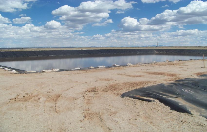
EVAPORATION:
• Ponds designed to store and evaporate
  production and flow back water.
• Top layer of the pond liner is textured surface
  60-mil HDPE.
• Climate at these sites is ideal in the semi-arid
  mountain west for evaporation during May
  through October.
• HDPE liner aided evaporation due to black
  color of surface.
• Water quality = 10,000 to 70,000 ppm TDS,
  mostly in the 30,000 ppm range.
EVAPORATION:
Net Evaporation - TEXAS
EVAPORATION:

•   Annual design net evaporation rates estimated to be approximately:

         Danish Flats = 50 inches
         Southern Cross = 40 inches
         Silo Field = 45 inches
         Wright = 45 inches

•   Danish Flats = actual annual evaporation encountered during 2008 was nearly 70
    inches (an increase of nearly 30%); in 2009 and 2010 was nearly 60 inches
    (increase ~17%); and for 2012 was measured at 42 inches for only the period May
    through August.

•   At Southern Cross in 2010 was approx. 55 inches (increase ~28%).

•   At Silo Field was approximately 52 inches inches per year in 2014.

•   At Wright was approximately = 30 inches in July 2017, including evaporation
    equipment.
Evaporation is enhanced using the surface of the HDPE geomembrane.
Evaporation is enhanced using atomizers that spray fine
mist above the water…~5,000 bbls/day evaporated
(depending).
EVAPORATION:

• During ideal conditions for evaporation (May
  through October) of water which has been found
  to be up to 1-inch (approx.) per day on the
  hottest days in July in August.

• During low evaporative months of November
  through April, the facilities store the water in the
  ponds.
Ideal conditions for
evaporation occurs
when:
– The air temperature
  is above 80 degrees
  Fahrenheit and
  sunny,
– Low humidity,
– The wind blows, and
– The level of water in
  a pond is not greater
  than 3 feet deep.
MAINTENANCE:

• After several years of operation (possibly 8 to 10
  years), the “salt” from the production or brine
  water builds up as precipitate in the pond
  bottoms.

• Upon excessive build-up of sediments or upon
  closure, then all the water is evaporated and the
  sediments dried and either removed or the
  facility buried (closure).
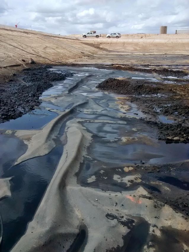
Wyoming - Sediments in pond bottoms after removal of
 water for liner repairs; pond operational 7 years.
 Water was 13,000 ppm to 66,000 ppm TDS.
Sediments removed
by hand using
shovels and power
washer, then wheel
barrow the
sediments to the top
of the pond. Load
the dried sediments
in waste trucks for
disposal at oilfield
waste landfills.
Liner can be “white” color instead of black in order to
reduce evaporation. Also, reduces wrinkles due to
less deformation due to heat/cold effects.
Ponds can be covered with a floating cover to
minimize evaporation.
Liner can be conductive HDPE with white or
black finish. Holes are found with wand.
Permian ponds from the air.
CONCLUSIONS:
• Evaporation facilities are serving a need of
  the region and the oil/gas industry.
• Evaporation of production/flow back water
  is a low cost method for disposal.
• HDPE as the top layer is the right choice
  due to proven durability and resistance to
  UV and chemical degradation.
• HDPE improves the evaporative ability of
  the ponds with the black color of the liner.
• Ponds can be covered or liner can be
  white to reduce evaporation.
Questions are welcomed.
Thank you for your interest.
              Presented by:
             Neil Nowak, PE
          Phone: 303-256-3005
   Email: nnowak@scsengineers.com
      Website: scsengineers.com
You can also read