High energy implementation of coil-target scheme for guided re- acceleration of laser-driven protons - Queen's University Belfast
←
→
Page content transcription
If your browser does not render page correctly, please read the page content below
High energy implementation of coil-target scheme for guided re-
acceleration of laser-driven protons
Ahmed, H., Hadjisolomou, P., Naughton, K., Alejo, A., Brauckmann, S., Cantono, G., Ferguson, S., Cerchez, M.,
Doria, D., Green, J., Gwynne, D., Hodge, T., Kumar, D., Macchi, A., Prasad, R., Willi, O., Borghesi, M., & Kar, S.
(2021). High energy implementation of coil-target scheme for guided re-acceleration of laser-driven protons.
Scientific Reports, 11(1), [669]. https://doi.org/10.1038/s41598-020-77997-w
Published in:
Scientific Reports

Document Version:
Publisher's PDF, also known as Version of record

Queen's University Belfast - Research Portal:
Link to publication record in Queen's University Belfast Research Portal

Publisher rights
Copyright 2021 the authors.
This is an open access article published under a Creative Commons Attribution License (https://creativecommons.org/licenses/by/4.0/),
which permits unrestricted use, distribution and reproduction in any medium, provided the author and source are cited.

General rights
Copyright for the publications made accessible via the Queen's University Belfast Research Portal is retained by the author(s) and / or other
copyright owners and it is a condition of accessing these publications that users recognise and abide by the legal requirements associated
with these rights.

Take down policy
The Research Portal is Queen's institutional repository that provides access to Queen's research output. Every effort has been made to
ensure that content in the Research Portal does not infringe any person's rights, or applicable UK laws. If you discover content in the
Research Portal that you believe breaches copyright or violates any law, please contact openaccess@qub.ac.uk.

Download date:13. Oct. 2021
www.nature.com/scientificreports
OPEN High energy implementation
of coil‑target scheme for guided
re‑acceleration of laser‑driven
protons
Hamad Ahmed1,2*, Prokopis Hadjisolomou1,3, Kealan Naughton1, Aaron Alejo1,
Stephanie Brauckmann4, Giada Cantono1,5, Simon Ferguson1, Mirela Cerchez4,
Domenico Doria1,6, James Green2, Deborah Gwynne1, Thomas Hodge1, Deepak Kumar3,
Andrea Macchi5,7, Rajendra Prasad4, Oswald Willi4, Marco Borghesi1 & Satyabrata Kar1*
Developing compact ion accelerators using intense lasers is a very active area of research, motivated
by a strong applicative potential in science, industry and healthcare. However, proposed applications
in medical therapy, as well as in nuclear and particle physics demand a strict control of ion energy,
as well as of the angular and spectral distribution of ion beam, beyond the intrinsic limitations of
the several acceleration mechanisms explored so far. Here we report on the production of highly
collimated (∼ 0.2◦ half angle divergence), high-charge (10s of pC) and quasi-monoenergetic proton
beams up to ∼ 50 MeV, using a recently developed method based on helical coil targetry. In this
concept, ions accelerated from a laser-irradiated foil are post-accelerated and conditioned in a helical
structure positioned at the rear of the foil. The pencil beam of protons was produced by guided
post-acceleration at a rate of ∼ 2 GeV/m, without sacrificing the excellent beam emittance of the
laser-driven proton beams. 3D particle tracing simulations indicate the possibility of sustaining
high acceleration gradients over extended helical coil lengths, thus maximising the gain from such
miniature accelerating modules.
Current interest in laser-driven ion accelerators, as a radically different, compact alternative to RF accelera-
tors, stems from remarkable properties such as large particle flux, short pulse duration and exceptional beam
emittance1. However, the large angular and spectral spread of the ion beams which are intrinsic to laser-driven
acceleration mechanisms, pose significant technical challenges to their applicative use. For instance, application
in cancer therapy would require the delivery of high energy protons (60–250 MeV)2–4 with narrow energy spread
and sufficient particle flux at significant distances from the interaction targets, so that the extraneous radiation
produced during the intense laser interaction can be shielded adequately. There has been recent significant pro-
gress in increasing the maximum proton energies delivered through laser-driven processes, with recent reports
of the acceleration of near 100 MeV p rotons5,6, albeit with a broad spectral content and large angular spread,
with an half cone divergence of 5◦ − 10◦ at the highest energies.
Control of the beam divergence and of its energy spectrum have been key research objectives over the past
decade, and a number of approaches using magnetic systems, target or plasma e ngineering7–13 have been explored
for this purpose. The recently developed scheme based on helical coil (HC) t argets14 offers, in this context, a
miniature and versatile setup that, in addition to reducing the divergence and energy spread of the beams, has
been shown to post-accelerate the guided protons at a rate of the order of GV/m. In this scheme, the electromag-
netic (EM) pulse generated due to transient charging of an intense-laser irradiated f oil14–18 is directed to travel
1
School of Mathematics and Physics, Queen’s University Belfast, Belfast BT71NN, UK. 2Central Laser Facility,
STFC Rutherford Appleton Laboratory, Didcot OX11 0QX, UK. 3Institute of Physics of the ASCR, ELI-Beamlines
Project, Na Slovance 2, 18221 Prague, Czech Republic. 4Institute for Laser and Plasma Physics, University of
Düsseldorf, Düsseldorf, Germany. 5Dipartimento di Fisica Enrico Fermi, Università di Pisa, Pisa, Italy. 6Extreme
Light Infrastructure (ELI-NP) and Horia Hulubei National Institute for R & D in Physics and Nuclear Engineering
(IFIN-HH), Reactorului No. 30, 077125 Magurele, Bucharest, Romania. 7National Research Council, National
Institute of Optics (CNR/INO), Research Unit “Adriano Gozzini”, Pisa, Italy. *email: hahmed02@qub.ac.uk; s.kar@
qub.ac.uk
Scientific Reports | (2021) 11:699 | https://doi.org/10.1038/s41598-020-77997-w 1
Vol.:(0123456789)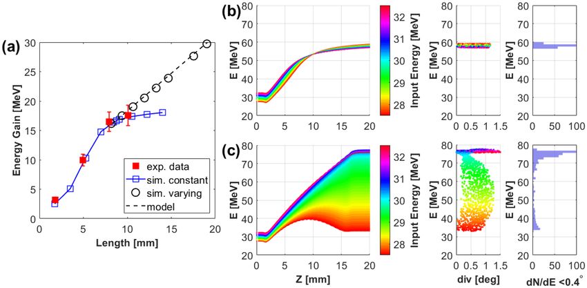
www.nature.com/scientificreports/
Figure 1. (a) Schematic of the setup (not to scale) used in the experiment. The HCs were made of 0.125 mm
thick stainless steel wire and had pitch, internal diameter and length of 0.7 ± 0.025 mm, 0.7 ± 0.015 mm and
7.7 ± 0.1 mm respectively. The HC was placed at 1.5 ± 0.05 mm from a ∼ 10 µm gold (Au) foil and connected
to the foil by a delay line of length 6 ± 0.1 mm. The Radiochromic films (RCF) stack detector was placed at
60 ± 1 mm from the interaction foil. Proton beam footprints captured by different RCF layers in the stack,
corresponding to different proton energies, are shown in (b-1) - (b-5). The scale shown at the top right corner
of (b-3) refers to the RCF plane. Zoomed-in views of the dose profiles for the high energy pencil beams are
shown in (b-4i), (b-5i), (c-i) and (c-ii), where the last two snapshots are obtained from a second shot during
the campaign using very similar laser and target parameters. The white-dashed circles on the zoomed-in views
corresponds to the internal diameter of the HC. (d) shows the comparison between a typical proton spectrum
obtained from reference flat foil targets and three HC target shots, RCF images from two of which (labelled
as HC target-1 and HC target-2, respectively) are shown in (b,c). The spectrum labelled as HC target-3 was
obtained from a shot taken at similar interaction conditions, using a HC target syncing similar energy protons
(∼30 MeV) as in case of (b,c) with an internal diameter and pitch of 0.5 ± 0.015 mm and 0.5 ± 0.02 mm
respectively. The on-axis proton spectra were obtained from the RCF data, as described in refs.22,28, considering
the proton dose from the area enclosed by the black-dashed circles in the zoomed-in RCF views, corresponding
to 0.33◦ half angle divergence (10−4 sr). The error bars were estimated considering the error in dose c onversion22
and uncertainties in background subtraction.
along the helical path defined by an HC. The characteristics of the EM pulse are governed by the generation of
hot electrons and their dynamics during the laser interaction and hence depend on a number of laser and target
parameters17,18. While traveling along the windings of the HC, the EM pulse generates a strong electric field pat-
tern which travels along the coil with a speed depending on the coil radius and pitch. Through a suitable choice
of these parameters, it can be made to match the speed at which 10s of MeV protons travel. Deploying the coil at
the rear side of the laser irradiated foil, protons within a narrow energy range are allowed to co-propagate with
the travelling field pattern, enabling the synchronised proton bunch to be guided and post-accelerated simulta-
neously under the effect of the radial and longitudinal components of the electric fi eld14,19.
In this article, we demonstrate the generation of highly directional beams (half-angle divergence ∼ 0.2◦) of
protons with energies up to ∼ 50 MeV and narrow energy spread (∼ 10% FWHM), by employing HC targets at
petawatt-class laser systems. The proton flux in the pencil beam at the spectral peak (∼ 45 MeV) is of the order
of 1012/MeV/sr, which is orders of magnitude higher than the fluxes typically generated by the TNSA mechanism
at the high energy end of the spectrum5,6,20,21. Particle tracing simulations corroborate the experimental results,
showing synchronous focusing and post-acceleration of transiting protons at a rate of ∼2 GeV/m, about four
times larger than reported in the first demonstration of the HC t echnique14 and well beyond the capabilities of
conventional RF accelerators. The scaling for Ti:Sa systems have been discussed in the ref.14, which shows that
acceleration gradients of multi-GeV/m can be achieved with ultra-short, petawatt class lasers. A current limita-
tion of the scheme will be discussed, together with a possible scheme to overcome it towards the production of
beamlets at energies of therapeutic interest.
Results
The data presented in this paper were collected from two experimental campaigns employing similar laser param-
eters, (see “Materials and methods” section for details). Fig. 1a shows a schematic of the HC target employed in
the experiments, where the HC was placed at a few millimetres away from the interaction foil, and connected to
the interaction foil by a metallic wire (the ‘delay line’). This configuration enabled precise control of the arrival
time at the HC of the EM pulse relative to the arrival of the protons from the foil by either varying the length of
Scientific Reports | (2021) 11:699 | https://doi.org/10.1038/s41598-020-77997-w 2
Vol:.(1234567890)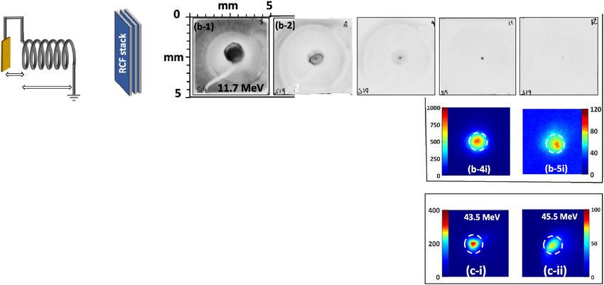
www.nature.com/scientificreports/
Figure 2. (a) and (b) highlight the dynamics of transiting protons through the HC obtained by particle tracing
simulations, carried out using a source delivering a poly-energetic and divergent beam of protons in the setup
shown in Fig 1a, with dimensions of the HC target used for the case shown in Fig. 1b. The simulation used the
EM pulse profile measured in the experiment by proton probing, in a similar way as described in ref.16 and
follows the propagation of protons with initial energy in the range of 25-35 MeV ( i.e. with energies close to
synchronisation with the moving field for this specific target design). (a) shows the change in energy of protons
while travelling along the HC axis Z (with proton source at z=0 mm and HC spanning from z = 1.5 to 9.2 mm,
as per the experimental setup). (b) shows their divergence at z = 20 mm, i.e. ∼ 1 cm after emerging from the
HC. In both graphs, the vertical axis refers to final output energy of the protons while the colormap indicates
their energy at the source. (c–e) show the energy spectrum, temporal and spatial spread respectively for protons
in the collimated beam, having half angle divergence θ < 0.4◦.
the delay line, or the distance between the HC and the foil. Fig. 1b,c show results relating to the production of
pencil beams of protons with a narrow energy bandwidth peaking at ∼ 45 MeV. As can be seen in Fig. 1b,c, the
experimental data shows a highly collimated beamlet with energies up to ∼ 49 MeV, well beyond the maximum
proton energies observed from reference flat foil shots taken during the campaign. The diameter of the central
bright spot (containing more than 75% of the total flux) at the detector (Radiochromic film (RCF)) plane, 60
mm away from the target, is less than the internal diameter of the HC (shown by the black dashed circles in the
zoomed-in views of the RCF images in Fig.1b,c). The spectral profile of the guided beam produced by the HC was
reconstructed from the RCF data, as shown in Fig. 1d. Compared to the exponentially decaying spectra obtained
from the reference flat foil shot, as typically expected from the TNSA mechanism, the on-axis proton spectra
from the HC targets showed a pronounced, narrow spectral peak at ∼ 45 MeV with a full width at half maximum
(FWHM) energy spread of less than 10% and peak prominence better than an order of magnitude. The number
of protons at the spectral peak was of the order of 108 /MeV (proton flux of the order of 1012 /MeV/sr ), which
one could filter out (for instance, by using conventional accelerator optics23,24) from the rest of the spectrum to
deliver narrow-band, collimated proton beams for applications.
The pencil beam of high energy protons results from the unique capability of chromatic guiding and post-
acceleration offered by the HC targets. For a given HC radius and pitch, the strong focussing and accelerating
fields move longitudinally along the HC axis with a fixed speed, which for the case shown in Fig. 1 was close to
that of 30 MeV protons. At a given time the field pattern spans over a few windings of the HC as described in
ref.14. While the maximum focusing field exists over the plane defined by the location the peak of the EM pulse,
the accelerating field is optimum at a small distance (a few hundreds of microns depending on the HC radius and
pitch) ahead of this p osition14. The delay line design of the HC targets, as used in the experiment, aids injecting
the appropriate energy protons slightly ahead of the EM pulse peak, so that the protons clutch to the leading part
of the field pattern and experience the optimum accelerating field.
Figure 2 illustrates the dynamics of transiting protons through the HC target, as reconstructed through
particle tracing simulations employing the PTRACE code (see “Materials and methods” section). In Fig. 2a,
the HC is seen accelerating efficiently the leading bunch of protons (28 ± 1 MeV ) entering the HC, whereas the
lower energy protons entering later in time, i.e. after the arrival of the EM pulse peak, are decelerated due to the
reversal of the longitudinal field, which points towards the proton source in the trailing part of the field pattern.
Furthermore, as shown in Fig. 2b, within the accelerated bunch, the fastest protons which are sufficiently ahead
of the EM pulse peak do not experience a strong focussing field and exit the HC without significant divergence
reduction. Therefore, it is protons from a narrow slice of the input spectrum which emerge with an extremely
low divergence and a significant energy gain—this simultaneous effect of energy-selection, focussing and post-
acceleration is a capability unique to the HC targets. As indicated in Fig. 2, the HC target used for the shots shown
Scientific Reports | (2021) 11:699 | https://doi.org/10.1038/s41598-020-77997-w 3
Vol.:(0123456789)www.nature.com/scientificreports/
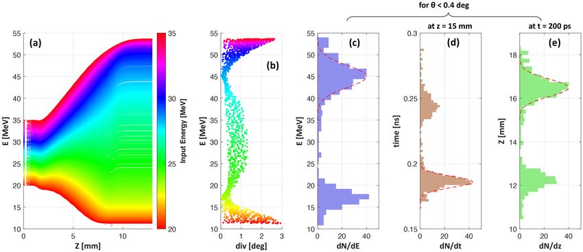
Figure 3. (a) Experimental setup (not to scale) used for characterizing the degree of beam collimation achieved
by HC targets. Irradiating identical HC targets at similar laser conditions, proton beams were diagnosed
by placing the RCF stack at different distances from the interaction foil. The HC targets used in this case
were made of 0.125 mm thick Stainless steel wire of internal diameter, pitch and length of 0.7 ± 0.015 mm,
0.35 ± 0.015 mm and 10 ± 0.1 mm respectively , designed to synchronise optimally with ∼9 MeV protons and
post-accelerate them to ∼30 MeV. (b–d) show spatial profiles of ∼30 MeV proton beams captured by the RCF
stack placed at 60 ± 1 mm, 100 ± 1 mm and 200 ± 1 mm respectively. (e) shows the 3D dose profile of the
proton beam shown in (c).
in Fig. 1b acted efficiently on protons of 28 ± 1 MeV, delivering a pencil beam of ∼45 MeV with 6 MeV FWHM
bandwidth (Fig. 2c), in a good agreement with the experimental results shown in Fig. 1d.
As shown in Fig. 1b,c, the diameter of the guided beam at 60 mm away from the target is smaller than the
internal diameter (0.7 mm) of the HC, which indicates a half-angle divergence less than 0.33◦. In order to char-
acterise more precisely the beam divergence, beam profiles from three HC targets of 0.7 ± 0.015 mm internal
diameter and 0.35 ± 0.015 mm pitch were recorded at different distances from the targets. Fig. 3b–d show beam
profiles taken at 60 mm, 100 mm, and 200 mm from the interaction foil. As can be seen in Fig. 3e, the peak dose
at 100 mm from the interaction foil is still several hundreds of Gy, providing ample scope for high dose delivery to
a remote irradiation site, as required by numerous applications. The beam waist (FWHM) of 0.6 ± 0.05 mm at 60
mm, expanded to 1.5 ± 0.1 mm at 200 mm, corresponds to a nominal half-angle at half-maximum divergence of
∼ 0.2◦. Taking the 0.7 mm diameter exit aperture of the HC as an upper estimate for the source size of the pencil
beam, an upper limit for the beam’s normalised transverse emittance (≃ βp r0 �θ , where βp is the ratio between
proton velocity to speed of light in vacuum, r0 being the source radius and �θ being the half angle divergence of
the beam) can be estimated as 0.15π mm mrad , indicating that the exceptional transverse emittance of TNSA
beams (orders of magnitude lower than in RF accelerators)25,26 is substantially preserved.
The HC module is essentially a travelling-wave linear accelerator, where the accelerating field moves with
the protons, so that the synchronised bunch of protons inside the HC experience a quasi-uniform field over an
extended distance which favours the conservation of their longitudinal emittance. As can be seen in Fig. 2d,e,
the collimated bunch of protons at around 45 MeV exits with an extremely low temporal and longitudinal spread
(FWHM spreads of 10 ps and 0.94 mm respectively). Such ultra-short, localised bunch of ions could therefore
be injected efficiently in subsequent stages of post-acceleration, for example using separate HC modules as
proposed in ref.14.
Discussion
While multi-staging of HC targets offers an attractive route towards a robust,‘all-optical’ accelerator, there is
significant scope for performance optimisation of a single stage. A key parameter towards increasing energy
gain is the length (L) of the accelerating module, which for the data shown in Fig. 1b was 7.7 mm. The effect
of L on post-acceleration was studied experimentally by deploying HCs of different lengths (2-10 mm), while
keeping the same radius and pitch (see Fig 4 caption for details). As can be seen in Fig. 4a, the experimental
data shows a steady increase in energy of the guided protons with the HC length up to L ∼ 8 mm. The particle
tracing simulations indicate that a steady energy gain of 2.1 ± 0.1 MeV/mm was maintained within this range.
For longer HCs however, the net energy gain saturates, as can be seen clearly from the simulations, which are in
agreement with the data obtained from the 10 mm long HC.
This saturation is due to dephasing between the accelerated bunch of protons and the travelling field pattern,
since an increase in proton energy by tens of MeV will lead to protons overruning the field pattern, which for
the case shown in Fig. 4a occurs after 8 mm of propagation. This problem can be mitigated by varying, continu-
ously or in steps, either the radius or the pitch (or both), of the HC to maintain the travelling field pattern in
phase with the protons.
The necessary modification to the HC geometry can be estimated by a simple analytical model as described
here. Protons of energy Ep (z) = γp (z) mp c 2 = mp c 2 + Tin + Gz , where mp is the proton rest mass, c is the speed
of light in vacuum, Tin is the kinetic energy of the protons entering the HC and G is the energy gain per unit
Scientific Reports | (2021) 11:699 | https://doi.org/10.1038/s41598-020-77997-w 4
Vol:.(1234567890)www.nature.com/scientificreports/
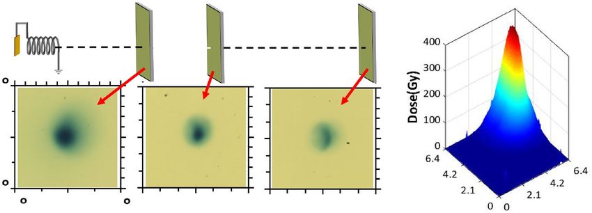
Figure 4. (a) Energy gain as a function of length of the HC target obtained from experiment (red) and
simulations (Blue). The HC targets ( 0.7 ± 0.015 mm internal diameter and 0.35 ± 0.015 mm pitch) used in this
case were similar to that used for the data shown in Fig. 3, except the length of HC which was varied from 2 to
10 mm. The simulations were carried out using the particle tracing code, as in Fig. 2, reconstructing the physical
dimensions of the HCs used in the experiment and scanning for the HC length beyond the range studied in
the experiment. The black circles show the simulated energy gain from a suitably designed varying pitch HC
as calculated from the analytical model discussed in the text. (b) and (c) show dynamics of transiting protons
(in a similar fashion as Fig. 2) through a constant and a variable pitched HCs, respectively. The HCs in both
cases extend from z=1.5 to 16.5 mm with internal diameter 0.5 mm and initial pitch 0.5 mm. While the HC in
(b) maintains a constant pitch over its full length, the pitch in (c) was varied according to Eq. (1), which gives
a pitch increase of ∼ 13µm per turn. The beam divergence shown in (b,c) were taken at z = 100 mm and the
energy spectra were plotted for a half-angle divergence < 0.4◦.
length inside the HC, need to remain at a fixed distance in front of the peak of the EM pulse, which requires the
electric field pattern to travel with the same velocity as the protons at any given z. The velocity of the travelling
field can be varied by changing either the radius or the pitch of the HC. For the purpose of this calculation we
consider the pitch variation only as these are easier to implement in practice. The longitudinal velocity of the field
pattern inside the HC can be expressed as vz (z) = cβEM p(z)/ (2πr)2 + p2 (z) , where r and p are the diameter
and pitch of the HC respectively and βEM = vEM /c , where vEM is the velocity of the EM pulse along a straight
wire, which was measured experimentally as ∼ 0.98 ± 0.02c14,16,17. Equating the velocity of the travelling field
to the proton velocity, one can find an expression for varying pitch to maintain a constant acceleration over an
extended length,
γp2 (z) − 1
p(z) = 2πr
2 (1)
(βEM − 1)γp2 (z) + 1
Figure 4a shows the predicted effectiveness of using varying pitch HCs over HCs fixed pitch HCs. While the
accelerated protons start to dephase significantly after 8 mm of propagation inside the constant pitch HC, simu-
lations shows that the energy gain can be maintained at the previous rate for an extended length of the HC by
increasing the pitch according to the formula shown above. As we increase the acceleration gradient (G), either
by increasing the amplitude of the EM pulse (as expected at multi-petawatt laser f acilities14), and/or decreasing
the radius (r) of the HC, using variable pitch HCs will be needed to maximize acceleration capabilities. As an
example, Fig. 4b,c further elaborate the benefit of using a variable pitch HC over a constant pitch HC. For this
comparison, HCs of 0.5 mm internal diameter were used which would provide G ∼ 3.0 MeV/mm with the same
EM pulse produced in our experiment. While dephasing between proton bunch and electric field pattern in the
constant pitch HC terminates the energy gain prematurely part way through the HC, the simulation suggests
that a suitably designed variable pitch HC of 15 mm length could have produced a narrow bandwidth pencil
beam of ∼75 MeV, i.e at an energy already adequate for treating ocular tumours or subcutaneous cancers for
instance, and that could be further enhanced by deploying successive, separately driven and optimized HC stages.
Materials and methods
Experiment. Experiments were conducted at two different facilities, namely the Titan laser system at Law-
rence Livermore National Laboratory (LLNL, USA) and the VULCAN Petawatt (VPW) system at Rutherford
Appleton Laboratory (RAL, UK). They are both Nd:Glass based laser systems operating at central wavelength of
Scientific Reports | (2021) 11:699 | https://doi.org/10.1038/s41598-020-77997-w 5
Vol.:(0123456789)www.nature.com/scientificreports/
1.053 µm. In the Titan experiment, CPA pulses of duration 600 ± 100 fs and energy 150 ± 25 J were focused on
target by an f/3 off-axis parabola to a spot of 7 ± 0.5 µm FWHM delivering peak intensity (2±1) × 1020 W/cm2.
In the second experiment, VPW delivered laser pulses of 1 ± 0.1 ps duration with energy 300 ± 50 J. The laser
pulses were focused by an f/3 off-axis parabola to a spot of 5.5 ± 0.5 µm FWHM, resulting in peak intensity
(3.5±1) × 1020 W/cm2. In both experiments, 10 µm thick gold foils were used for proton generation, HCs were
made of 0.125 mm stainless steel wire and the laser was incident at 20◦ to the target normal. The spatial and spec-
tral distribution of the proton beams was characterised by deploying a stack of dosimetrically calibrated Radi-
ochromic films (RCF)22. The proton spectra were reconstructed by spectral deconvolution of the dose deposited
in the RCF layers27, by using an iterative algorithm similar to the procedures used in refs.22,28. Starting from the
last RCF layer in the stack, the final spectrum is produced by calculating spectra between Bragg peak energies of
consecutive RCF layers, while considering the energy response of the RCF layers (simulated by SRIM29) in the
stack and subtracting the dose contribution in a given layer by the protons stopping deeper in the stack.
Simulations. The particle tracing simulations presented in this paper were performed using the PTRACE
c ode30, which simulates the propagation in 3D of protons from source to detector through the region where e.m.
fields are present in this case the field pattern produced by the EM pulse travelling along a HC target. The protons
transit through the HC together with the co-propagating electric field associated to the travelling EM pulse. The
protons are traced by computing relativistic equations of motion using a Runge-Kutta fourth-order algorithm
coupled with an adaptive step size monitoring routine. The HC was modelled in PTRACE using a cylindrical
co-ordinate system and the physical dimensions as used in the experiment. An EM pulse of peak linear charge
density 50 µC/m, 5 ps half-maximum rise and 15 ps half-maximum decay, similar to that measured experimen-
tally in both the campaigns using the technique of self-probing (described in the r ef16), was set to travel along
the HC wire. In the delay line configuration, the proton source was modelled as a point source located on the
axis of the HC at a given distance from the entrance plane of the HC, emitting protons towards the HC with a
given energy spectrum and divergence, mimicking the proton beam produced by the reference flat foil target.
Received: 25 June 2020; Accepted: 27 October 2020
References
1. Macchi, A., Borghesi, M. & Passoni, M. Ion acceleration by superintense laser-plasma interaction. Rev. Mod. Physics 85, 751 (2013).
2. Bulanov, S. V. et al. Oncological hadrontherapy with laser ion accelerators. Phys. Lett. A 299, 240 (2002).
3. Malka, V. et al. Practicality of proton therapy using compact laser systems. Med. Phys. 31, 1587 (2004).
4. Linz, U. & Alonso, J. What will it take for laser driven proton accelerators to be applied to tumour therapy?. Phys. Rev. STAB 10,
094801 (2007).
5. Wagner, F. et al. Maximum proton energy above 85 MeV from the relativistic interaction of laser pulses with micrometer thick
CH 2 targets. Phys. Rev. Lett. 116, 205002 (2016).
6. Higginson, A. et al. Near-100MeV protons via a laser-driven transparency-enhanced hybrid acceleration scheme. Nat. Commun
9, 724 (2018).
7. Kar, S. et al. Dynamic control of laser-produced proton beams. Phys. Rev. Lett. 100, 105004 (2008).
8. Bartal, T. et al. Focusing of short-pulse high-intensity laser-accelerated proton beams. Nat. Phys. 8, 139 (2012).
9. Kar, S. et al. Ballistic focusing of polyenergetic protons driven by petawatt laser pulses. Phys. Rev. Lett. 106, 225003 (2011).
10. Patel, P. et al. Isochoric heating of solid-density matter with an ultrafast proton beam. Phys. Rev. Lett. 91, 125004 (2003).
11. Toncian, T. et al. Ultrafast laser-driven microlens to focus and energy-select mega-electron volt protons. Science 312, 410 (2006).
12. Busold, S. et al. Focusing and transport of high-intensity multi-MeV proton bunches from a compact laser-driven source. Phys.
Rev. Sp. Top. Acc. Beams 16, 101302 (2013).
13. Schollmeier, M. et al. Controlled transport and focusing of laser-accelerated protons with miniature magnetic devices. Phys. Rev.
Lett. 101, 055004 (2008).
14. Kar, S. et al. Guided post-acceleration of laser-driven ions by a miniature modular structure. Nat. Commun 7, 10792 (2016).
15. Quinn, K. et al. Laser-driven ultrafast field propagation on solid surfaces. Phys. Rev. Lett. 102, 194801 (2009).
16. Ahmed, H. et al. Investigations of ultrafast charge dynamics in laser-irradiated targets by a self probing technique employing laser
driven protons. Nucl. Instrum. Methods A 829, 172 (2016).
17. Ahmed, H. et al. Efficient post-acceleration of protons in helical coil targets driven by sub-ps laser pulses. Sci. Rep 7, 10891 (2017).
18. Aktan, E. et al. Parametric study of a high amplitude electromagnetic pulse driven by an intense laser. Phys. Plasmas 26, 070701
(2019).
19. Kar, S. et al. Dynamic control of laser driven proton beams by exploiting self-generated, ultrashort electromagnetic pulses. Phys.
Plasma 23, 055711 (2016).
20. Snavely, R. A. et al. Intense high-energy proton beams from Petawatt-laser irradiation of solids. Phys. Rev. Lett. 85, 2945 (2000).
21. Gaillard, S. A. et al. Increased laser-accelerated proton energies via direct laser-light-pressure acceleration of electrons in microcone
targets. Phys. Plasmas. 18, 056710 (2011).
22. Kirby, D. et al. Radiochromic film spectroscopy of laser accelerated proton beams using the FLUKA code and dosimetry traceable
to primary standards. Laser Particle Beams 29, 231 (2011).
23. Scuderi, V. et al. Development of an energy selector system for laser-driven proton beam applications. Nucl. Instrum. Methods A
740, 87 (2014).
24. Margarone, D. et al. ELIMAIA: A laser-driven ion accelerator for multidisciplinary applications. Quantum. Beam. Sci. 2, 2 (2018).
25. Borghesi, M. et al. Multi-MeV proton source investigations in ultraintense laser-foil interactions. Phys. Rev. Lett. 92, 055003 (2004).
26. Cowan, T. E. et al. Ultralow emittance, multi-MeV proton beams from a laser virtual-cathode plasma accelerator. Phys. Rev. Lett.
92, 204801 (2004).
27. Markey, K. Development of Laser Accelerated MeV Ion Sources. PhD thesis (Queen’s University, Belfast, 2009).
28. Breschi, E. et al. A new algorithm for spectral and spatial reconstruction of proton beams from dosimetric measurements. Nucl.
Instrum. Methods A 522, 190–195 (2004).
29. SRIM—The Stopping and Range of Ions in Matter. https://www.srim.org.
30. Schiavi, A. Study of Laser Produced Plasmas by X-ray and Proton Radiography. Ph.D. thesis (Imperial College, London, 2003).
Scientific Reports | (2021) 11:699 | https://doi.org/10.1038/s41598-020-77997-w 6
Vol:.(1234567890)www.nature.com/scientificreports/
Acknowledgements
Authors acknowledge funding from EPSRC [EP/J002550/1-Career Acceleration Fellowship held by S.K., EP/
L002221/1, EP/K022415/1, EP/J500094/1, and EP/I029206/1], SFB/TR18, GRK1203, EC-GA284464, and Invest
Northern Ireland (POC-329). D.K., acknowledges the financial support of the Ministry of Education, Youth
and Sports, via project LQ1606, as part of targeted support from the National Programme of Sustainability II
(Czechia). Authors also acknowledge A. Schiavi for the use of the particle tracing code, PTRACE and Dr. Jason
Wiggins for insightful suggestions. Data associated with research published in this paper is accessible at https://
doi.org/10.17034/4f68d8a8-21b4-48bd-9a32-e31101a60197.
Author contributions
The experiment was designed and led by H.A., M.B., S.K. and supported by P.H., K.N., A.A., S.B., G.C., M.C.,
D.D., J.G., D.G., T.H., D.K. and R.P. The data was analysed by PH, SF, HA and SK. The manuscript was written
by H.A., M.B. and S.K.; A.M. and O.W. were involved in discussions.
Competing interests
The authors declare no competing interests.
Additional information
Correspondence and requests for materials should be addressed to H.A. or S.K.
Reprints and permissions information is available at www.nature.com/reprints.
Publisher’s note Springer Nature remains neutral with regard to jurisdictional claims in published maps and
institutional affiliations.
Open Access This article is licensed under a Creative Commons Attribution 4.0 International
License, which permits use, sharing, adaptation, distribution and reproduction in any medium or
format, as long as you give appropriate credit to the original author(s) and the source, provide a link to the
Creative Commons licence, and indicate if changes were made. The images or other third party material in this
article are included in the article’s Creative Commons licence, unless indicated otherwise in a credit line to the
material. If material is not included in the article’s Creative Commons licence and your intended use is not
permitted by statutory regulation or exceeds the permitted use, you will need to obtain permission directly from
the copyright holder. To view a copy of this licence, visit http://creativecommons.org/licenses/by/4.0/.
© The Author(s) 2021
Scientific Reports | (2021) 11:699 | https://doi.org/10.1038/s41598-020-77997-w 7
Vol.:(0123456789)You can also read