The Role of Balancing Nanostructured Silicon Anodes and NMC Cathodes in Lithium-Ion Full-Cells with High Volumetric Energy Density - IOPscience
←
→
Page content transcription
If your browser does not render page correctly, please read the page content below
Journal of The Electrochemical
Society

OPEN ACCESS

The Role of Balancing Nanostructured Silicon Anodes and NMC
Cathodes in Lithium-Ion Full-Cells with High Volumetric Energy Density
To cite this article: Anne Baasner et al 2020 J. Electrochem. Soc. 167 020516

View the article online for updates and enhancements.

                               This content was downloaded from IP address 176.9.8.24 on 05/05/2020 at 19:34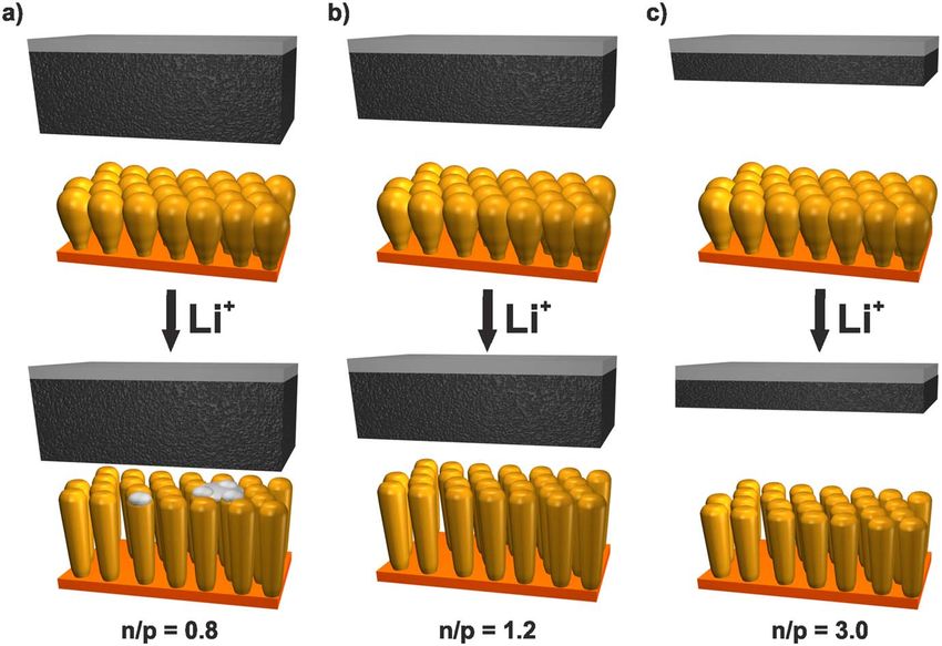
Journal of The Electrochemical Society, 2020 167 020516

                             The Role of Balancing Nanostructured Silicon Anodes and NMC
                             Cathodes in Lithium-Ion Full-Cells with High Volumetric Energy
                             Density
                             Anne Baasner,1,2 Florian Reuter,1,2,* Matthias Seidel,3 Andreas Krause,4 Erik Pflug,2
                             Paul Härtel,2 Susanne Dörfler,2,z Thomas Abendroth,2 Holger Althues,2 and Stefan Kaskel1,2
                             1
                               Chair of Inorganic Chemistry, Dresden University of Technology, 01062 Dresden, Germany
                             2
                               Fraunhofer Institute for Material and Beam Technology IWS, 01277 Dresden, Germany
                             3
                               Fraunhofer Institute for Ceramic Technologies and Systems IKTS, 01277 Dresden, Germany
                             4
                               Namlab gGmbH Dresden, 01187 Dresden, Germany

               Silicon anodes offer a very promising approach to boost the energy density of lithium-ion batteries. While silicon anodes show a
               high capacity and, depending on the system, a good cycle stability in half-cells vs lithium, their integration in industrially
               applicable lithium-ion full-cells is still challenging. Balancing described as the capacity ratio of negative and positive electrode (n/p
               ratio) is a crucial necessity for the successful design of lithium-ion batteries. In this work, three different silicon based anode
               systems, namely carbon coated silicon nanowires, columnar silicon thin films and silicon-carbon void structures are compared in
               LIB full cells containing NMC111 cathodes. By varying the areal capacity of the NMC111 cathode, the influence of the balancing
               was investigated over a broad n/p range of 0.8−3.2. The aim was to find an ideal compromise between lithium plating suppression,
               high cycling stability and maximized energy density. To underline the high volumetric energy density, the columnar silicon thin
               films are additionally analyzed in multilayered pouch cells with NMC622 and NMC811 cathodes resulting in 605 Wh L−1 and 135
               Wh kg−1 and even 806 Wh L−1 and 183 Wh kg−1 as demonstrated on stack level.
               © 2020 The Author(s). Published on behalf of The Electrochemical Society by IOP Publishing Limited. This is an open access
               article distributed under the terms of the Creative Commons Attribution 4.0 License (CC BY, http://creativecommons.org/licenses/
               by/4.0/), which permits unrestricted reuse of the work in any medium, provided the original work is properly cited. [DOI: 10.1149/
               1945-7111/ab68d7]

               Manuscript submitted October 28, 2019; revised manuscript received December 8, 2019. Published January 21, 2020.
               Supplementary material for this article is available online

     In terms of increasing the energy density of storage devices, the                LCO,16,43,51,56,60,65,68        LFP40,45,49,53,62,65 and   LNMO,54,63,64
                                                                                             41,42,44,46–48,50,57–59,66,69
state-of-the-art lithium-ion battery using a graphite anode is driven to              NCM                                  is the most frequently used cathode
its limits.1,2 To take the next step towards a new generation of lithium-             for the full-cells comprising silicon based anodes. Nevertheless, only a
ion batteries, silicon is an attractive anode material.2 The abundant                 few scientific articles focus on the balancing of lithium-ion full-cells
and non-toxic silicon has the highest lithiation capacity (3579 mAh                   with Si based anodes.59,66 More importantly, the research findings
g−1Si, 8303 mAh cm−3, Li15Si4) among all materials forming lithium                    being gained so far are hardly comparable with each other due to
alloys and a low delithiation voltage around 0.4 V vs Li/Li+.3–5                      different cell set-ups (different coins cells or Swagelok types) and un-
Moreover, techniques to generate silicon materials are established.                   realistic thick glass-fiber separators soaked with electrolyte excess
Unfortunately, silicon undergoes a large undesirable volume expan-                    reducing the energy density. In order to transfer results from coin to
sion during lithiation and delithiation leading to pulverization and loss             prototype cell level, application-relevant separators should be used.
of contact between silicon and the current collector. This negatively                 The balancing described by the n/p ratio is defined as the capacity
affects the capacity retention and the Coulombic efficiency (CE).4,6–9                 ratio of negative to positive electrode (n/p ratio) and is crucial for the
Moreover, the solid electrolyte interphase (SEI) formed on the silicon                performance of the lithium-ion full-cells.70 Importantly, lithium
surface by electrolyte decomposition is cracked by the mechanical                     plating should be prevented due to the irreversible loss of active
stress of the volume change. It is formed repeatedly consuming                        lithium ions and possible internal short-circuits leading to safety
lithium ions and electrolyte leading to cell dry-out.10–13                            issues.71 On the other hand, a higher oversized anode is detrimental
Several strategies based on nanostructured silicon like silicon                       for the energy density of the resulting cells.72 Kierzeck et al.’s59
nanowires,14–17 silicon particles,18–23 columnar silicon thin                         investigation of Si–C composite coupled with NMC cathode shows
films24–27 have been reported so far. To stabilize the SEI and improve                 that a slightly oversized anode improves the stability compared to n/p
the electrical contact, silicon-carbon composites with a free volume                  ∼1, and that the anode achieves a higher initial capacity than a larger
between the silicon core and the carbon shell have been                               oversized Si–C anode at the same time.59 Herein, three different
introduced.28–35 Overall, silicon based anodes with application-                      representative silicon nanostructures (silicon nanowires, columnar
relevant areal capacities and high cycle stabilities provide a high                   silicon thin films, and silicon-carbon void structures) with an
capacity retention in half-cells vs a lithium anode where irreversible                application-relevant separator and areal capacity above 2 mAh cm−2
capacity loss is masked by the lithium excess though.14,25,36,37                      are matched with a NMC111 cathode in coin cells under comparative
Logically, the next step is the integration of these silicon based                    conditions. By varying the mass loading of the NMC111 cathode, a
anodes in lithium-ion full-cells.1,38 Graphene silicon composites                     wide range of n/p ratios between 0.8–3.2 is realized to investigate the
with 15%–60% silicon are the most widely investigated Si                              influence of the balancing on the cycle stability and to define an
containing anodes in full-cells during the last years.39–52                           optimal n/p ratio preventing lithium plating and irreversible lithium
Furthermore, composites of carbon black and silicon particles                         loss. The results reveal an outstanding potential of the columnar
(SiNPs),53–58 carbon covered silicon particles59,60 and silicon coated                silicon thin film anode multilayered pouch cells. Therefore, these
carbon fibers16,61 have been already tested in full-cells. Pure silicon                anodes were also evaluated vs NMC622 and NMC811 cathodes to
anode structures without carbon and binders like silicon thin                         demonstrate the high volumetric energy density.
films are rarely used.25,62–66 Besides NCA,25,39,51,52,55,61,65,67
                                                                                                                      Experimental
  *Electrochemical Society Student Member.                                              Silicon-carbon composite anode.—20.31 g SiNPs (Alfa Aesar,
  z
    E-mail: susanne.doerfler@iws.fraunhofer.de                                         98%, APS ⩾ 50 nm) and 59.60 g PVB (B60HH, Mowital) were
Journal of The Electrochemical Society, 2020 167 020516
mixed with a mortar mill (PULVERISETTE 2, Retsch) for 10 min contains 1 M lithium hexafluorophosphate (LiPF6) in 1:1 (v/v)
and heated for 30 min at 190 °C. 70.23 g Si@PVB composite was ethylene carbonate and dimethyl carbonate. Through the galvano-
ground with the mortar mill for 10 min and suspended in 310 ml static cycling, which was performed with a BaSyTec CTS cell test
deionized water and 34 ml ethanol. 101.07 g sucrose (Sigma system, the Si/Li half-cells were discharged (lithiated) and charged
Aldrich) and 6.8 g 2.5 M sodium hydroxide (Carl Roth) solution (delithiated) with a C-rate of C/20 during the first cycle and C/10
were added under stirring. The mixture was heated for 3 h at 100 °C during the following cycles between 10 mV−1 V. The C-rate was
and 6 h at 160 °C. The ground compound was heated under argon based on the theoretical capacity of the silicon (3579 mAh g−1Si).
flow with 10 K min−1 to 850 °C and kept for 2 h. A water based During the formation, the NMC/Li half-cells were cycled two times
slurry containing 80 wt% Si–C, 10 wt% multiwalled carbon with a C-rate of C/10 between 3−4.3 V while a CV step until C/100
nanotubes (MWCNT, Nanocyl7000, 90%) and 10 wt% styrene- (1C = 140 mA g−1 based on the mass of NMC) was applied during
butadiene rubber (SBR, Targray, 15%) was prepared with a mixer charge and discharge. Two cycles with a rate of C/5 and CV step
mill (MM400, Retsch) at 25 Hz for 15 min. It was coated on a until C/50 followed. The subsequent cycling was performed with C/
copper foil (9 μm) with an automatic film applicator (BYK) and the 5 between 3.0−4.3 V, and a CV step was just applied at the end of
coatings were dried at 80 °C for 2 h. The resulting Si–C anodes have the charge.
a density of 0.6 g cm−3 and a loading of 4.3−4.8 mg cm−2.
Full-cell testing.—The balancing is determined based on the
Columnar silicon thin film anode.—Columnar silicon thin films ratio of the areal capacity of the anode to the cathode which are
with a silicon loading of 0.85 mg cm-2 were prepared by magnetron deduced from the theoretical capacity of the silicon (3579 mAh
sputtering (Multi Sputter Lab 600, VTD Vakuumtechnik Dresden g−1Si) and from the practical capacity of NMC111 (140 mA
GmbH) of silicon (99.99%) onto a 10 μm roughened copper foil g−1NMC). This results in a wide range of the n/p ratios between
with copper dendrites (SE-Cu58 Schlenk Metallfolien GmbH & Co. 0.8−4.2. CR2016 coin cells containing a dried Si anode (diameter 16
KG) at 10−6 mbar. The a-Si anodes have a thickness of 10 μm and a mm) and NMC111 cathode (diameter 15 mm) were assembled in an
density of 0.85 g cm−3. argon filled glovebox (MBraun) with less than 0.1 ppm O2 and H2O.
An Al2O3 impregnated polyethylene terephthalate separator FS3002
Carbon coated silicon nanowires.—Au nanoparticles were used from Freudenberg (diameter 19 mm, 23 μm thick), a stainless steel
as catalyst for the Si-NW and were deposited onto pyrolytic graphite spacer (1 mm thick) and 40 μl LP30 + 10% FEC (99.9%, Solvionic
sheets (Panasonic EYG-S121803 and EYG-S121807) via thermal SA) are used. Before full-cell testing, the Si–C anodes were
evaporation of Au (5N purity) in a customized evaporation system assembled in a half-cell and lithiated/delithiated between 50 mV–1
(Bestec GmbH, base pressure 5 · 10−7 mbar). In a customized low V with a current density of 0.1 mA cm−2 in the 1st cycle and 0.5 mA
power chemical vapor deposition (CVD) furnace (ATV-Tech cm−1 in the following cycle to previously form a SEI. The
GmbH, base pressure 5 · 10−2 mbar) Si-NW were grown with a galvanostatic cycling was performed with a BaSyTec CTS cell test
precursor gas mixture of SiH4:H2 (1:5, 5N:5N purity) and a pressure system. The formation of the NMC111/Si-NW full-cells contains
of 150 mbar. Subsequently, a pyrolytic carbon layer was grown onto two cycles with C/10 and two cycles with C/5 between 3−4.3 V and
the Si-NW in the same furnace at 820 °C with a gas mixture of a CV step until 10% of the cathode capacity (140 mAh g−1NMC)
C2H4:N2 (3:10, 5N:5N purity) at a pressure of 100 mbar. The steps during charge and discharge. The subsequent cycling in the same
Au deposition, Si-NW growth, carbon layer growth were executed voltage range was performed with C/5. To increase the capacity, the
repeatedly. NMC111/a-Si and the NMC111/Si_C full-cells were charged until
2.4 V and a constant voltage step until 10% of the theoretical
Lithium nickel manganese cobalt oxide (NMC111) cathode.— capacity was introduced. After the full-cell testing, the cells were
A NMP based slurry comprising 91.4% NMC111 (TODA), 4.4% disassembled and rebuilt in half-cells with a fresh lithium chip and
carbon black (Timcal) and 4.1% PVDF (Polymers France) was electrolyte. The same test procedures as for the half-cell character-
coated on a 30 μm thick aluminum foil. The coating thickness was ization but without formation cycles were used.
varied to obtain loadings of 8.5, 9.0, 14.5, 16.0, 17.0, 17.5, 19.5,
20.0, 23.0, 25.5 and 28.0 mg cm−2, which ensure a broad areal Prototype cells.—Multilayered pouch cells (71 × 46 mm2) were
capacity range between 1.2–3.6 mAh cm−2. The NMC cathodes assembled in a glovebox using a double-sided silicon thin film anode
were calandered to a porosity of 38% and a density of ∼2.4 g cm−3. (0.91 mg cm-2, 3.3 mAh cm−2, 0.91 g cm−3). As cathode was used
either NMC811 (12.6 mg cm-2, 2 mAh cm−2, 2.8 g cm−3) purchased
Structural characterization.—The structure of Si-NW was im- from Custom Cells or NMC622 (14.2 mg cm-2, 2.3 mAh cm−2, 2.5 g
aged by the scanning electron microscope (SEM) ZEISS GEMINI cm−3) which was processed similar to the NMC111 cathode. The
LEO 1560 with a Bruker in-lens detector and 5 kV acceleration NMC622/a-Si pouch cells contain the same separator as the coin
voltage. The SEM JSM-6610LV from JEOL with a secondary cells and 1.65 ml of the electrolyte LP30 + 10% FEC. A thinner
electron detector and 5−10 kV acceleration voltage was used to polyethylene separator (12 μm) and 1 ml LP30 +10% FEC are used
analyze the columnar silicon thin films. The nanoscale structure and in the NMC811/a-Si pouch cells. For the pouch cell, the test
morphology of the Si–C was examined with the transmission procedure was similar to the coin cell testing.
electron microscope (TEM) JEM-2100 from JEOL (200 kV accel-
eration voltage). To quantify the silicon content of the Si–C, it was Results and Discussion
heated under argon with 10 K min−1 to 500 °C and held for 30 min
and heated again with 5 K min−1 to 1000 °C and held for 30 min Production and characterization of representative silicon na-
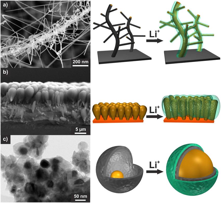
using a Netzsch STA 409 PC/PG simultaneous thermal analyzer. nostructures.—Three different silicon structures shown in Fig. 1 are
compared, namely (1) silicon nanowires (Si-NW), (2) amorphous
Half-cell testing.—The Si and the NMC electrodes (diameter 12 columnar silicon thin films (a-Si), and (3) nanostructured silicon-
mm) were dried at 80 °C under vacuum for 12 h and were tested vs a carbon composite void structures (Si–C). Si-NW are deposited onto
lithium anode (99.9%, diameter 16.5 mm, 250 μm thick, MTI pyrolytic graphite sheets and coated with a pyrolytic carbon layer.
Corporation). In an argon filled glovebox (MBraun) with less than These synthesis steps are repeated to achieve a branched tree-like
0.1 ppm O2 and H2O. CR2016 coin cells (MTI Corp.) were structure (supplementary Fig. S1, available online at stacks.iop.org/
assembled with the Al2O3 impregnated polyethylene terephthalate JES/167/020516/mmedia) and a silicon loading of 0.8−1.4 mg
separator FS3002 by Freudenberg (diameter 19 mm, 22 μm thick), a cm−2. The a-Si with a silicon loading of 0.9 mg cm−2 are achieved
stainless steel spacer (1 mm thick) and 30 μl LP30 + 10% by sputtering Si onto copper foil with a rough layer of copper
fluoroethylene carbonate (FEC). LP30 (99.9%, Solvionic SA) dendrites.24 The Si–C containing 28% Si is synthesized via a simple,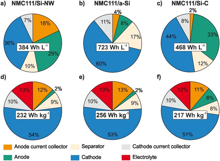
Journal of The Electrochemical Society, 2020 167 020516

Figure 1. SEM or TEM image and schematic illustration of the lithiation of silicon nanowires (Si-NW, a), columnar silicon thin films (a-Si, b) and silicon-
carbon void structures (Si–C, c) and the resulting SEI morphology (green).

potentially scalable route without hydrofluoric acid treatment similar          structures, the a-Si thin films have the highest ICE of 94.2%
to a process as described elsewhere.73 Polyvinylbutyral (PVB) is               followed by the Si-NW with 90.3%. The Si–C was synthesized by
herein used as intermediate template which could be removed                    sucrose as precursor which is known to form porous irregular carbon
completely during pyrolysis to create tailored voids between                   coatings, increasing the number of reactive sites and lowering the
SiNPs and carbon shells. In contrast to the Si-NW and the a-Si,                ICE to 45.3%.73–75 As shown in Fig. 2b, the initial irreversible
the Si–C could be easily incorporated in the slurry coating process            capacity of the Si–C is much higher than the ones of the a-Si and Si-
which is actually used for LIB.                                                NW. Therefore, we decided to (pre)cycle the Si–C anode in a half-
    All three Si nanostructures were galvanostatically cycled in half-         cell vs lithium before full-cell testing to form the SEI. In conclusion,
cells vs a Li anode (Fig. 2). The a-Si thin film has the highest specific        all three silicon structures show relatively high capacity retention
capacity. In the second cycle, 3313 mAh g−1Si are achieved, which              and application-relevant areal capacity.
is close to the theoretical capacity (3579 mAh g−1). The Si-NW and
the Si–C electrode have a specific capacity above 2100 mAh g−1Si in                 Electrochemical performance of the NMC111/Si full-cells.—
the second cycle. The capacities based on the mass of the electrode            The three representative Si anodes are matched with a NMC111
without current collector and the areal capacities are descripted in           cathode, which shows a stable capacity of 140 mAh g−1NMC in half-
the ESI (Fig. S2). All anodes have a practically applicable areal              cells (Fig. S3). Areal capacities between 1.2−3.6 mAh cm−2 were
capacity above 2 mAh cm−2. During the 1st cycle, there is the initial          realized by adapting the mass loading (8.5−28 mg cm−2). The n/p
formation of the SEI which results in an initial Coulombic efficiency           ratio is determined based on the ratio of the areal capacity of the
(ICE) lower than 100% and a high irreversible capacity. Due to the             anode to the cathode which are deduced from the theoretical capacity
relatively low surface to volume ratio compared to the other two               of the silicon (3579 mAh g−1Si) for a better comparability of the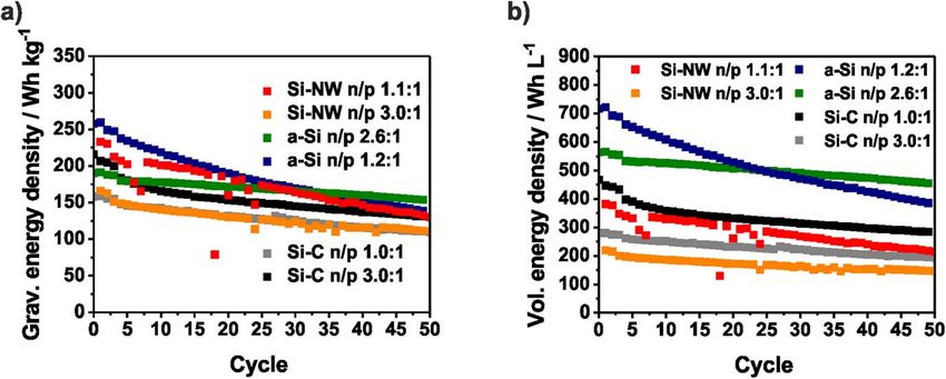
Journal of The Electrochemical Society, 2020 167 020516

Figure 2. Specific discharge capacities, Coulombic efficiencies (CE) (a) and accumulated irreversible capacities (b) of the Si-NW, the a-Si and the Si–C
electrode vs a lithium anode in a half-cell set-up.

three silicon systems and from the practical capacity of NMC111                 silicon electrodes is applied and the electrode stability in half-cells
(140 mA g−1NMC). Therefore, a wide range of the n/p ratios between              could be significantly improved.76 Nevertheless, the higher anode
0.8−4.2 is covered. For better clarity and to compensate the error in           mass has to be taken into account which decreases the energy
the determination of the silicon loading, the individual n/p ratios are         density. In addition, as it can be seen from the voltage profiles of the
summarized to n/p ranges with the same characteristics. In the                  NMC cathode and Si anode derived from the half-cell tests in Fig. 4a
following sections, the influence of the balancing on the cycle                  the upper voltage of the cathode is increased by the higher voltage of
stability is discussed to define an optimal n/p ratio preventing                 the Si anode if it is not completely utilized (n/p = 3). In case of an
lithium plating and increase the energy density.                                oversized NMC cathode the potential of the Si anodes falls below 0
                                                                                V and lithium is plated. Ideally, both electrodes are balanced and the
    NMC111/Si-NW full-cells.—In Fig. 3, the specific capacities of               cut-off voltage of the NMC111 cathode is around 4.2 V. A similar
the NMC111/Si-NW full-cells based on the mass of NMC are                        correlation was described by Kasnatscheew et al.77 for LIB full-cells
averaged over several coin cells of the same n/p range. The colored             with graphite anodes. The influence of the Si potential vs Li/Li+
area contains the minimum and the maximum values of the capacity.               could be seen in Fig. 3b where the 1st charge capacity increased with
For better clarity, the averaged CE is shown without error bars. In             the n/p ratio. The ICE seemed to be independent from n/p at around
cells with an n/p ratio below 1.1 the capacity drops directly. Due to           77%.
the higher capacity of the positive electrode, the negative electrode is            To investigate the electrode degradation during the full-cell test,
charged below 0 V vs Li/Li+ and lithium plating takes place. This               after 50 cycles both electrodes were reassembled in half-cells. Indeed,
loss of active lithium ions causes the capacity fading and the low              an n/p ⩽ 1.0 leads to cathode degradation and a capacity of less than
CE.72 There is no obvious difference between the n/p ranges 1.1−1.3             100 mAh g−1NMC could be provided (Fig. 4b). With an n/p ratio
and 1.4−2.5. Only during the 1st cycle, the capacity slightly rises             between 1.1−1.7, a stable capacity of 125 mAh g−1NMC could be
with increasing n/p ratio. However, with n/p ⩾ 3.0 the capacity                 achieved which matches with the results from the previous half-cell
retention is significantly improved and 100 mAh g−1NMC could be                  testing (Fig. S3). A lower capacity is reached with an n/p ratio ⩾1.8.
reached after 50 cycles. Since the Si-NW anode is highly oversized,             As discussed before, the charge cut-off voltage at the cathode
it is only partially lithiated and only around 1200 mAh g−1Si are               increased with the n/p ratio and above 4.6 V, both the NMC111
utilized. In several works, a similar limitation of the capacity of             cathode and the organic electrolyte begin to degrade (Fig. S3).

Figure 3. Specific discharge capacities and Coulombic efficiencies of NMC111/Si-NW full-cells (a). The data of duplicate cells with the same n/p range are
averaged and the colored area contains the minimum and the maximum values. First charge capacities and initial Coulombic efficiencies (ICE) depending on the
n/p ratio (b).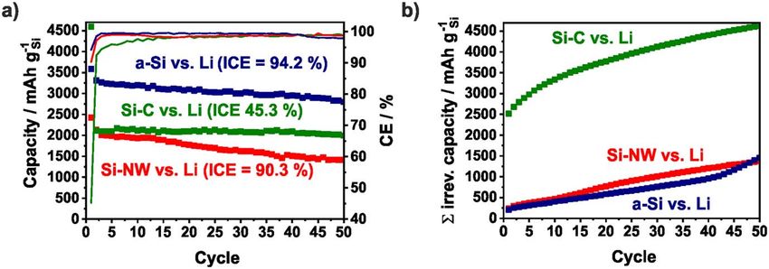
Journal of The Electrochemical Society, 2020 167 020516

Figure 4. Schematic illustration of the voltage profiles of the NMC111 cathode and a Si anode in half cells (a) and averaged discharge capacities (b) of NMC
cathodes in rebuilt half-cells after full-cell testing (NMC111/Si-NW) with different n/p ratios.

Nevertheless, these cells are more stable indicating that improved Si           therefore higher than that of the NMC111/Si-NW cell (∼77%)
anode stability and the lower lithium losses have a large influence on           indicating a lower irreversible capacity (Fig. 5b). Nevertheless, the
the performance. It should be mentioned that the Si-NW are partially            specific charge capacity follows the same trend as in the NMC111/
detached from the carbon current collector which is pictured in Fig.            Si-NW full-cell and increases with the n/p ratio. Due to the sloping
S4. Therefore, the utilized capacity is lower than 1000 mAh g−1Si in            portion of anode voltage profile and the only partially utilized anode,
the reassembled cells (Fig. S5).                                                the upper voltage of the cathode is increased. This is why the
                                                                                capacity of the full-cells with n/p 1.4–2.0 is slightly higher than that
    NMC111/a-Si full-cells.—The specific capacities and the CE of                of the full-cells with n/p 1.2−1.3. Both electrodes after 50 cycles are
the NMC111/a-Si full-cells are shown in Fig. 5a. Compared to the                depicted in Fig. S6 and results of the rebuilt half-cells are shown in
NMC111/Si-NW full-cells, the lower cut-off voltage is changed                   Fig. 7. While the NMC cathodes originated from full-cells with n/p
from 3 V to 2.4 V and a constant voltage step is introduced during              between 1.2−2.0 show a stable capacity of 125 mAh g−1NMC in the
charging in order to increase the capacity and also the energy density          half-cells, the capacity of the NMC cathodes for the full-cell with
of the full-cell. While the NMC111/Si-NW full-cells show a stable               lower or higher n/p ratios are lower than 100 mAh g−1NMC. If n/p ⩾
capacity above an n/p ratio of 1.0, in case of the NMC/a-Si full-cells,         2.5, the NMC is driven to a critical upper cut-off voltage (Fig. 4a). In
the n/p ratio needs to be higher than 1.1 to prevent lithium plating            case of the full-cell with n/p ⩽ 1.1, the reason for the cathode
(Fig. 6a). There are no significant differences between the n/p ranges           degradation is not clear and should be analyzed in further investiga-
of 1.2−1.3 and 1.4−2.0 in the first cycle when ∼160 mAh g−1NMC                   tions. The a-Si anodes used in the full-cells with an n/p ratio between
are achieved (Fig. 5a). However, if the silicon anode is only partially         1.2−3.0 show a lithiation capacity (discharge capacity) below 2000
lithiated (n/p ⩾ 2.5), a higher capacity and significant improved                mAh g−1Si (Fig. 7b), implying ∼1000 mAh g−1Si reduced capacity
capacity retention of more than 80% after 50 cycles (168 mAh                    than in the preceding half-cell test (Fig. 2). A reason for this finding
g−1NMC) is reached (Fig. 6c). The initial CE from the NMC111/a-Si               is the mechanical degradation of the a-Si film during the cycling.
cell with n/p ⩾ 1.2 is independent of the n/p ratio around 90% and              Due to the lithium plating the Si electrodes from the full-cells with

Figure 5. Specific discharge capacities and Coulombic efficiencies of NMC111/a-Si full-cells (a). The data of duplicate cells with the same n/p range are
averaged and the colored area contains the minimum and the maximum values. First charge capacities and initial Coulombic efficiencies (ICE) depending on the
n/p ratio (b).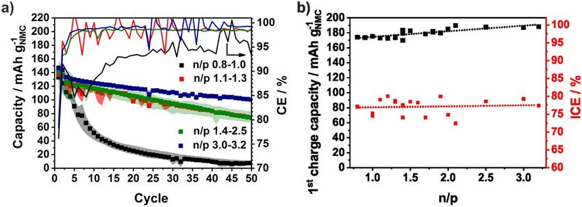
Journal of The Electrochemical Society, 2020 167 020516

Figure 6. Schematic illustration of the NMC111/a-Si full cell with oversized positive electrode where lithium is plated (a), slightly oversized negative electrode
(b) and largely oversized negative electrode which is thereby just partially utilized (c).

Figure 7. Averaged discharge capacities of the NMC cathodes (a) and the a-Si anodes (b) in rebuilt half-cells after full-cell testing (NMC111/a-Si) with varying
n/p ratios.

an n/p ⩽ 1.1 degrades and achieved only 1000 mAh g−1Si in rebuilt                   cells with n/p = 0.8 have a low discharge capacity of approx. 100
half-cells.                                                                         mAhg−1NMC due to the lithium plating which is usually accom-
                                                                                    panied by irreversible lithium loss. With an n/p of 1.0−1.1, a
   NMC111/Si–C full-cells.—As already mentioned, the Si–C an-                       reasonable capacity utilization of 137 mAh g−1NMC in the 1st cycle is
odes were (pre)cycled in a half-cell before full-cell testing to form               reached, indicating that the lithium plating could be prevented, as
the SEI, otherwise a large amount of the lithium stored in the NMC                  expected, by the increased anode areal capacity. Using a higher
cathode would be consumed by the initial SEI formation (Fig. S7).                   oversized negative electrode (n/p = 1.7−2.5) the capacity of the
Figure 8 shows the averaged discharge and charge capacity and the                   NMC111/Si–C full-cells with n/p 1.7−2.5 is increased to 158 mAh
resulting CE as a function of the n/p ratio. The NMC111/Si–C full-                  g−1NMC in the 1st cycle and degrades to 103 mAh g−1NMC after 50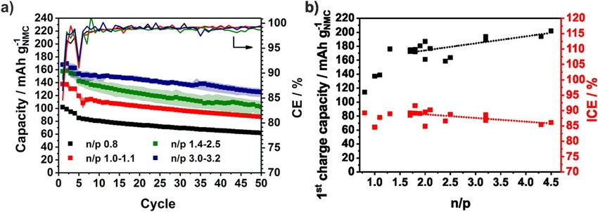
Journal of The Electrochemical Society, 2020 167 020516

Figure 8. Specific discharge capacities and Coulombic efficiencies of NMC111/Si–C full-cells (a). The data of several duplicate cells with the same n/p range
are averaged and the colored area contains the minimum and the maximum values. First charge capacities and initial Coulombic efficiencies (ICE) depending on
the n/p ratio (b).

cycles. According to the prior results, the highest capacity (168 mAh               Figure 10 shows the cell design and Fig. 11 the resulting weight
g−1NMC in the 1st cycle and 137 mAh g−1NMC in the 50th cycle)                   and volume distribution and the volumetric and specific energy
could be achieved with an n/p ratio above 3.0. Due to the precycling            density of the three full-cell concepts with a minimal n/p ratio based
and the resulting initial SEI formation on the Si–C anode in a                  on the calculation descripted in the supporting information. It has to
preceding half-cell operation, an ICE of 85%–92% similar to ICE of              be considered, that the increase in thickness during lithiation is not
the NMC111/a-Si full-cells and higher than the ICE the NMC111/Si-               taken into consideration, because it could not be undoubtedly
NW full-cells is achieved. As shown before, the 1stcharge capacity              deduced from coin cell investigations. We are aware that this is a
rises with the n/p ratio due to the voltage profile, the partially utilized      crucial parameter and therefore, investigations with multilayered
negative anode and causes the higher capacity. Figure 9 contains the            pouch cells are described in the following chapter.
results of the rebuilt half-cells of the Si anodes and NMC cathodes                 The Si-NW have a very low density which result in a high dead
after cycling. Just with high n/p ratios ⩾1.7, the NMC cathode                  volume filled with electrolyte, and a large electrode thickness.
provides a capacity of 125 mAh g−1NMC comparable with the                       Moreover, the used pyrolytic carbon sheet is much thicker than the
previous half-cell test. Below an n/p ratio of 1.7, the capacity of the         conventionally used copper foil. This is why the NMC111/Si-NW
NMC111 cathodes is lower than 90 mAh g−1NMC in the rebuilt half-                full-cells have the lowest volumetric energy density with 382 Wh L−1.
cells. In contrast, all Si–C anodes show a stable capacity around               Due to the dense columnar structure of the a-Si, a comparatively high
1800 mAh g−1NMC during the first cycles of the half-cell test which              volumetric energy density of 713 Wh L−1 is achieved. The overall
underlines the structural stability of the Si–C anode (Fig. S8).                porosity (76%) of the Si–C is lower than the porosity (95%) of the Si-
                                                                                NW approach. Despite the relatively low silicon content of 23%, a
   Comparison and estimation of the energy density based on the                 volumetric energy density of 466 Wh L−1 could be achieved due to
coin cell testing.—The energy density is a crucial parameter that               the thin copper current collector. The NMC111/a-Si full-cell has the
needs to be considered when discussing novel anode concepts.                    highest specific energy density of 256 Wh kg−1 followed by the
Usually, the practically usable energy densities could not be deduced           NMC111/Si-NW full-cell with 232 Wh kg−1 and NMC111/Si–C full-
directly from the theoretical energy densities of the active                    cell with 217 Wh kg−1. However, it has to be considered that the
materials.78 Here, we compare the energy density on stack level of              volumetric and especially the specific energy density of the three full-
the three full-cell concepts and the influence of the n/p ratio.                 cell concepts is strongly influenced by the NMC111 cathode which

Figure 9. Averaged discharge capacities of the NMC cathodes (a) and the Si–C anodes (b) in rebuilt half-cells after full-cell testing (NMC111/Si–C) with
varying n/p ratios.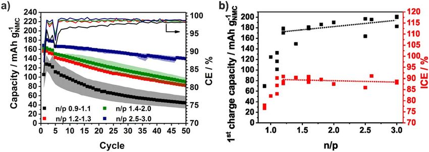
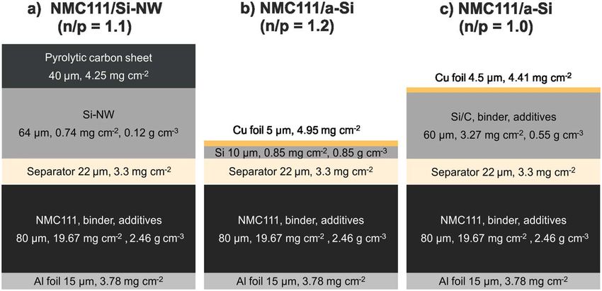
Journal of The Electrochemical Society, 2020 167 020516

Figure 10. Characteristics of the NMC111/Si full-cells components with a Si-NW, (a), a-Si (d) and Si–C (c) anode and a minimal n/p ratio without lithium
plating.

Figure 11. Theoretical calculation of the volumetric/specific energy density with the corresponding volume (a)–(c) and weight distribution (d)–(f) of the cell
components for NMC111/Si full-cells with a Si-NW (a), (d), a-Si (b), (e) and Si–C (c), (f) anode and a minimal n/p ratio without lithium plating.

has a volumetric fraction of 36%–60% and a mass fraction of                      especially in combination with disruptive silicon anode concepts.78–80
50%–53%. Therefore, NCA and nickel-rich NMC materials like                       If an optimal NCA cathode according to the energy calculation of
NMC622 or NMC811 with much higher capacities (180−210 mAh                        lithium-ion batteries by Betz et al.78 with a density of 3.05 g cm−3 and
g−1) and higher areal loading and mass density (3 g cm−3) are an                 a loading of 13 mg cm−2 is assumed, the energy density of the full-
effective option to further increase the volumetric energy density,              cells improves enormously (Fig. S9). While the NCA/Si-NW and the
Journal of The Electrochemical Society, 2020 167 020516

Figure 12. Estimated volumetric energy densities (a) and specific energy densities (b) of NMC111/Si full-cells depending on the Si anode structure and the n/p
ratio.

NCA/Si–C full-cells could reach 519 W L−1 and 336 Wh kg−1 or 681                 and the different wetting and pressure situation, especially for
W L−1 and 304 Wh kg−1, respectively, and with the a-Si anode even                electrodes that undergo volume changes. Summarizing, the electro-
1119 Wh L−1 and 326 Wh kg−1 are achievable. However, the                         chemical performance of the a-Si anode stands out against the other
concepts in this work are highly limited by the cathode and energy               two investigated Si systems by the high volumetric energy density and
densities of state-of-art batteries from Panasonic with and 683 Wh               are further investigated in prototype cells with NMC622 and NMC811
L−1 260 Wh kg−1 and where a NCA cathode and a carbon/silicon                     cathodes. As shown in Fig. 13, the NMC622/a-Si pouch cell and the
anode is probably used cannot be exceeded.81                                     NMC811/a-Si pouch cells reaches a higher capacity of 180 mAh
    In Fig. 12, the cycle stability for varying n/p ratios in the three          g−1NMC or 210 mAh g−1NMC, respectively, due to the higher Ni content
investigated systems based on the coin cell testing is shown. As                 of the NMC cathode. In both pouch cells, higher capacity retention than
expected and already discussed, an oversized silicon anode is                    in the coin cells is reached indicating a lower irreversible capacity by
beneficial for the cycle stability, but decreases the overall energy              side reactions or electrode degradation. Additionally, the pressure
density of the cell. In case of the NMC111/Si-NW and the NMC111/                 distribution differs drastically in pouch compared to coin cells. After 50
Si–C full-cells, the increased capacity could not compensate the                 cycles, indeed 70% (125 mAh g−1NMC) of the initial capacity could be
higher anode volume or weight (Fig. 12). However, the cycle                      achieved in the NMC622/a-Si pouch cells and the NMC811/a-Si
stability of NMC111/a-Si full-cell could be significantly improved                delivers still 67% (142 mAh g−1NMC). Consequently, a high initial CE
through the strongly oversized a-Si anode. Consequently, the                     of 92%–94% and of 99.2%–99.4% in the following cycles is achieved.
volumetric energy density and the specific density of the full-cell               Figures S10 and S11 display the pouch cells and their components after
with n/p = 2.6:1 is maintained after approx. 25−30 cycles, whereas               cycling. A deformation of the a-Si anodes similar to the coin cells and
full-cells with the minimal n/p ratio of 1.2:1 principally show an               previous studies is observed.24 Due to the volume change of the silicon,
accelerated degradation.                                                         a large mechanic stress is applied on the copper foil which leads to the
                                                                                 microscopic structural changes. Consequently, a few amount of silicon
   Prototype cells.—The evaluation of new battery materials in                   is delaminated and attached to the separator. The energy density of the
multilayered pouch cells is essential for the targeted application,              prototype cells is calculated on stack level considering inactive
especially due to new effects caused by double-sided electrode coatings          components like the separator and the current collectors. To allow a

Figure 13. Specific discharge capacities and Coulombic efficiencies of the NMC622/a-Si prototype cells (a) with a n/p of 1.4 containing two double-sided a-Si
anode, a double-sided and two single-sided NMC622 cathodes and of the NMC811/a-Si prototype cells (b) with a n/p of 1.9 containing a double-sided a-Si anode
and two single-sided NMC811 cathodes.
Journal of The Electrochemical Society, 2020 167 020516
better comparability with previous results the pouch foil and the taps 15. A. Krause, O. Tkacheva, A. Omar, U. Langklotz, L. Giebeler, S. Dörfler, F. Fauth,
are not considered. By using the NMC622 and the NMC811 cathode T. Mikolajick, and W. M. Weber, J. Electrochem. Soc., 166, A5378 (2019).
16. L.-F. Cui, Y. Yang, C.-M. Hsu, and Y. Cui, Nano Lett., 9, 3370 (2009).
material the capacity could be increased while the cathode weight and 17. V. Etacheri, O. Haik, Y. Goffer, G. A. Roberts, I. C. Stefan, R. Fasching, and
thickness is reduced at the same time. As a consequence, the multi- D. Aurbach, Langmuir, 28, 965 (2012).
layered NMC622/a-Si pouch cell achieves 605 Wh L−1 and 135 Wh 18. C. Erk, T. Brezesinski, H. Sommer, R. Schneider, and J. Janek, ACS Appl. Mater.
kg−1. In case of the NMC811/a-Si pouch cell, a thinner separator (12 Interfaces, 5, 7299 (2013).
19. A. Urbanski et al., J. Electrochem. Soc., 166, A5275 (2019).
μm) is used resulting in a relatively high volumetric energy density of 20. H. Gao et al., Nano Lett., 17, 1512 (2017).
806 Wh L−1 and a reasonable specific energy density of 183 Wh kg−1 21. C. C. Nguyen, T. Yoon, D. M. Seo, P. Guduru, and B. L. Lucht, ACS Appl. Mater.
on stack level. Interfaces, 8, 12211 (2016).
22. L. Luo, J. Wu, J. Luo, J. Huang, and V. P. Dravid, Sci. Rep., 4, 3863 (2014).
23. M. T. McDowell, S. W. Lee, J. T. Harris, B. A. Korgel, C. Wang, W. D. Nix, and
Conclusions Y. Cui, Nano Lett., 13, 758 (2013).
Three representative nanostructured silicon anode systems (Carbon 24. M. Piwko, T. Kuntze, S. Winkler, S. Straach, P. Härtel, H. Althues, and S. Kaskel,
J. Power Sources, 351, 183 (2017).
coated silicon nanowires (Si-NW), columnar silicon thin films (a-Si) 25. M. Piwko, S. Thieme, C. Weller, H. Althues, and S. Kaskel, J. Power Sources, 362,
and silicon-carbon void structures (Si–C)) were successfully coupled 349 (2017).
with NMC111 cathodes with various mass loadings to investigate the 26. E. Markevich et al., J. Electrochem. Soc., 160, A1824 (2013).
influence of the balancing on the full-cell performance. 27. R. Elazari, G. Salitra, G. Gershinsky, A. Garsuch, A. Panchenko, and D. Aurbach,
Electrochem. Commun., 14, 21 (2012).
The minimal n/p ratio which is needed to prevent lithium plating 28. N. Liu, H. Wu, M. T. McDowell, Y. Yao, C. Wang, and Y. Cui, Nano Lett., 12,
for each Si anode system was determined. Independent of the Si 3315 (2012).
structure, the cycle stability of the full-cell could be increased 29. S. Iwamura, H. Nishihara, and T. Kyotani, J. Phys. Chem. C, 116, 6004 (2012).
significantly by a three times oversized Si anode. The reason for 30. S. Chen, M. L. Gordin, R. Yi, G. Howlett, H. Sohn, and D. Wang, Phys. Chem.
Chem. Phys., 14, 12741 (2012).
this is the limited lithiation of the Si anode improving its stability 31. X. Li et al., J. Mater. Chem., 22, 11014 (2012).
during cycling, which is already known for half-cells. The three full- 32. N. Liu, Z. Lu, J. Zhao, M. T. McDowell, H.-W. Lee, W. Zhao, and Y. Cui, Nat.
cell set-ups were compared in terms of the theoretical energy density Nanotechnol., 9, 187 (2014).
of practical pouch cell stacks based on the material characteristics 33. H. Tao, L.-Z. Fan, W.-L. Song, M. Wu, X. He, and X. Qu, Nanoscale, 6, 3138 (2014).
34. C. Pang, H. Song, N. Li, and C. Wang, RSC Adv., 5, 6782 (2015).
before cycling. The highest volumetric energy density of 713 Wh L−1 35. L. Y. Yang, H. Z. Li, J. Liu, Z. Q. Sun, S. S. Tang, and M. Lei, Sci. Rep., 5, 10908
are estimated for the NMC111/a-Si-full cells. Based on these results, (2015).
the a-Si anodes were successfully cycled in multilayered pouch cells 36. J. Song, M. Zhou, R. Yi, T. Xu, M. L. Gordin, D. Tang, Z. Yu, M. Regula, and
with NMC622 and NMC811 cathodes, respectively. A high capacity D. Wang, Adv. Funct. Mater., 24, 5904 (2014).
37. Q. Xu, J.-Y. Li, J.-K. Sun, Y.-X. Yin, L.-J. Wan, and Y.-G. Guo, Adv. Energy
of 210 mAh g−1NMC, an improved CE (99.2%–99.4%), and cycle Mater., 7, 1601481 (2017).
stability compared to the coin cell testing was achieved resulting in a 38. V. Aravindan, Y.-S. Lee, and S. Madhavi, Adv. Energy Mater., 5, 1402225 (2015).
high volumetric energy density as high as 806 Wh L−1. 39. K. Eom, T. Joshi, A. Bordes, I. Do, and T. F. Fuller, J. Power Sources, 249, 118
Summarizing, this study reveals decisive specifications pre- (2014).
40. M. Wetjen, D. Pritzl, R. Jung, S. Solchenbach, R. Ghadimi, and H. A. Gasteiger,
venting lithium plating in viable full-cells with maximized specific J. Electrochem. Soc., 164, A2840 (2017).
energy and high cycle stability as a function of silicon anode 41. L. de Sutter, G. Berckmans, M. Marinaro, J. Smekens, Y. Firouz, M. Wohlfahrt-
architecture and its interaction with all cell components. Mehrens, J. van Mierlo, and N. Omar, Energies, 11, 2948 (2018).
42. G. Berckmans, L. de Sutter, M. Marinaro, J. Smekens, J. Jaguemont, M. Wohlfahrt-
Mehrens, J. van Mierlo, and N. Omar, Electrochim. Acta, 306, 387 (2019).
Acknowledgments 43. V. L. Chevrier, L. Liu, R. Wohl, A. Chandrasoma, J. A. Vega, K. W. Eberman,
P. Stegmaier, and E. Figgemeier, J. Electrochem. Soc., 165, A1129 (2018).
This research has received funding from the Federal Ministry of 44. M. Marinaro et al., J. Power Sources, 357, 188 (2017).
Education and Research through the project BamoSa (support code 45. F. Holtstiege, A. Wilken, M. Winter, and T. Placke, Phys. Chem. Chem. Phys., 19,
03X4637) and KaSiLi (support code 03XP0254). We would like to 25905 (2017).
thank A. Urbanski (Leibniz Institute of Polymer Research (IPF) 46. M. Klett, J. A. Gilbert, S. E. Trask, B. J. Polzin, A. N. Jansen, D. W. Dees, and D.
P. Abraham, J. Electrochem. Soc., 163, A875 (2016).
Dresden e.V.) and A. Omar (Leibniz Institute for Solid State and 47. D.-T. Nguyen, J. Kang, K.-M. Nam, Y. Paik, and S.-W. Song, J. Power Sources,
Material Research (IFW) Dresden e.V.) for useful discussions on 303, 150 (2016).
polymers and electrolytes and J. Strangalies (Fraunhofer Institute for 48. G. Berckmans et al., World Electr. Veh. J., 9, 43 (2018).
Material and Beam Technology IWS) for performing SEM measure- 49. W. M. Dose, V. A. Maroni, M. J. Piernas-Muñoz, S. E. Trask, I. Bloom, and C.
S. Johnson, J. Electrochem. Soc., 165, A2389 (2018).
ments and P. Fleischer (Fraunhofer Institute for Material and Beam 50. S. E. Trask, K. Z. Pupek, J. A. Gilbert, M. Klett, B. J. Polzin, A. N. Jansen, and D.
Technology IWS) manufacturing the pouch cells. P. Abraham, J. Electrochem. Soc., 163, A345 (2016).
51. A. J. Louli, J. Li, S. Trussler, C. R. Fell, and J. R. Dahn, J. Electrochem. Soc., 164,
References A2689 (2017).
52. A. Bordes, K. Eom, and T. F. Fuller, J. Power Sources, 257, 163 (2014).
1. K. Feng, M. Li, W. Liu, A. G. Kashkooli, X. Xiao, M. Cai, and Z. Chen, Small, 14, 53. H. Shobukawa, J. Alvarado, Y. Yang, and Y. S. Meng, J. Power Sources, 359, 173
1702737 (2018). (2017).
2. J. W. Choi and D. Aurbach, Nat. Rev. Mater., 1, 1401826 (2016). 54. G. Gabrielli, M. Marinaro, M. Mancini, P. Axmann, and M. Wohlfahrt-Mehrens,
3. T. Devic, B. Lestriez, and L. Roué, ACS Energy Lett., 4, 550 (2019). J. Power Sources, 351, 35 (2017).
4. M. N. Obrovac and L. Christensen, Electrochem. Solid-State Lett., 7, A93 (2004). 55. S. D. Beattie, M. J. Loveridge, M. J. Lain, S. Ferrari, B. J. Polzin, R. Bhagat, and
5. L. Baggetto, J. F. M. Oudenhoven, T. van Dongen, J. H. Klootwijk, M. Mulder, R. R. Dashwood, J. Power Sources, 302, 426 (2016).
A. H. Niessen, M. H. J. M. de Croon, and P. H. L. Notten, J. Power Sources, 189, 56. N. Delpuech, N. Dupre, P. Moreau, J.-S. Bridel, J. Gaubicher, B. Lestriez, and
402 (2009). D. Guyomard, ChemSusChem, 9, 841 (2016).
6. R. Chandrasekaran, A. Magasinski, G. Yushin, and T. F. Fuller, J. Electrochem. 57. J. H. Lee, C. S. Yoon, J.-Y. Hwang, S.-J. Kim, F. Maglia, P. Lamp, S.-T. Myung,
Soc., 157, A1139 (2010). and Y.-K. Sun, Energy Environ. Sci., 9, 2152 (2016).
7. M. Gu, Z. Wang, J. G. Connell, D. E. Perea, L. J. Lauhon, F. Gao, and C. Wang, 58. N. Dupré, P. Moreau, E. de Vito, L. Quazuguel, M. Boniface, A. Bordes,
ACS nano, 7, 6303 (2013). C. Rudisch, P. Bayle-Guillemaud, and D. Guyomard, Chem. Mater., 28, 2557
8. J. W. Wang et al., Nano Lett., 13, 709 (2013). (2016).
9. P. Limthongkul, Y.-I. Jang, N. J. Dudney, and Y.-M. Chiang, J. Power Sources, 59. K. Kierzek and J. Machnikowski, Electrochim. Acta, 192, 475 (2016).
119-121, 604 (2003). 60. W. Wang, Z. Favors, C. Li, C. Liu, R. Ye, C. Fu, K. Bozhilov, J. Guo, M. Ozkan,
10. M. B. Pinson and M. Z. Bazant, J. Electrochem. Soc., 160, A243 (2013). and C. S. Ozkan, Sci. Rep., 7, 44838 (2017).
11. S. P. V. Nadimpalli, V. A. Sethuraman, S. Dalavi, B. Lucht, M. J. Chon, V. 61. M. W. Forney, M. J. Ganter, J. W. Staub, R. D. Ridgley, and B. J. Landi, Nano Lett.,
B. Shenoy, and P. R. Guduru, J. Power Sources, 215, 145 (2012). 13, 4158 (2013).
12. H. Nakai, T. Kubota, A. Kita, and A. Kawashima, J. Electrochem. Soc., 158, A798 62. J.-K. Kim, G.-B. Cho, H.-S. Ryu, H.-J. Ahn, K.-K. Cho, K.-W. Kim, A. Matic,
(2011). P. Jacobsson, and J.-H. Ahn, Solid State Ion., 268, 256 (2014).
13. C. K. Chan, R. Ruffo, S. S. Hong, and Y. Cui, J. Power Sources, 189, 1132 (2009). 63. K. Fridman, R. Sharabi, R. Elazari, G. Gershinsky, E. Markevich, G. Salitra,
14. A. Krause et al., Sci. Rep., 6, 27982 (2016). D. Aurbach, A. Garsuch, and J. Lampert, Electrochem. Commun., 33, 31 (2013).Journal of The Electrochemical Society, 2020 167 020516
64. K. Fridman, R. Sharabi, E. Markevich, R. Elazari, G. Salitra, G. Gershinsky, 73. A. Baasner, S. Dörfler, M. Piwko, S. Desilani, J. Brückner, H. Althues, and
D. Aurbach, J. Lampert, and M. Schulz-Dobrick, ECS Electrochem. Lett., 2, A84 S. Kaskel, J. Mater. Chem. A, 6, 14787 (2018).
(2013). 74. W. Nickel, M. Oschatz, S. Rico-Francés, S. Klosz, T. Biemelt, G. Mondin,
65. F. Farmakis, C. Elmasides, P. Selinis, and N. Georgoulas, Electrochim. Acta, 245, A. Eychmüller, J. Silvestre-Albero, and S. Kaskel, Chem. Eur. J., 21, 14753 (2015).
99 (2017). 75. L. Borchardt, M. Oschatz, S. Graetz, M. R. Lohe, M. H. Rümmeli, and S. Kaskel,
66. F. Reuter, A. Baasner, J. Pampel, M. Piwko, S. Dörfler, H. Althues, and S. Kaskel, Micropor. Mesopor. Mat., 186, 163 (2014).
J. Electrochem. Soc., 166, A3265 (2019). 76. K. Kimura, T. Matsumoto, H. Nishihara, T. Kasukabe, T. Kyotani, and
67. H. J. Kim, S. Choi, S. J. Lee, M. W. Seo, J. G. Lee, E. Deniz, Y. J. Lee, E. K. Kim, H. Kobayashi, J. Electrochem. Soc., 164, A995 (2017).
and J. W. Choi, Nano Lett., 16, 282 (2016). 77. J. Kasnatscheew, T. Placke, B. Streipert, S. Rothermel, R. Wagner, P. Meister, I.
68. Y. Jin et al., Energy Environ. Sci., 10, 580 (2017). C. Laskovic, and M. Winter, J. Electrochem. Soc., 164, A2479 (2017).
69. W. Lu, L. Zhang, Y. Qin, and A. Jansen, J. Electrochem. Soc., 165, A2179 78. J. Betz, G. Bieker, P. Meister, T. Placke, M. Winter, and R. Schmuch, Adv. Energy
(2018). Mater., 9, 1803170 (2019).
70. B. Son, M.-H. Ryou, J. Choi, S.-H. Kim, J. M. Ko, and Y. M. Lee, J. Power 79. S.-T. Myung, F. Maglia, K.-J. Park, C. S. Yoon, P. Lamp, S.-J. Kim, and Y.-K. Sun,
Sources, 243, 641 (2013). ACS Energy Lett., 2, 196 (2017).
71. C.-S. Kim, K. M. Jeong, K. Kim, and C.-W. Yi, Electrochim. Acta, 155, 431 (2015). 80. V. Murray, D. S. Hall, and J. R. Dahn, J. Electrochem. Soc., 166, A329 (2019).
72. J. Kasnatscheew, R. Wagner, M. Winter, and I. Cekic-Laskovic, Top. Curr. Chem., 81. R. Schmuch, R. Wagner, G. Hörpel, T. Placke, and M. Winter, Nat. Energy, 3, 267
376, 16 (2018). (2018).You can also read