VWR INSTRUCTION MANUAL - Microscope
←
→
Page content transcription
If your browser does not render page correctly, please read the page content below
VWR
Microscope			               series 400

                 INSTRUCTION MANUAL

                   Model                 European Catalogue Number
                 IT405FLD                         630-2695

Version:   1
Issued:    27, 01, 2017
Legal Address of Manufacturer

Europe
VWR International bvba
Researchpark Haasrode 2020
Geldenaaksebaan 464
B-3001 Leuven
+ 32 16 385011
http://be.vwr.com

Country of origin: ITALY

                                 Table of Contents

Warning
Safety information
Package contents
Unpacking
Intended use
Symbols and conventions
Product specifications
Overview
Operation
Troubleshooting
Repair and maintenance
User replaceable accessories and spare parts
Technical service
Warranty
Compliance with local laws and regulations
Disposal

                                       2
Warning
This microscope is a scientific precision instrument designed to last for many years with a minimum of main-
tenance. It is built to high optical and mechanical standards and to withstand daily use.
We remind you that this manual contains important information on safety and maintenance, and that it must
therefore be made accessible to the instrument users.
We decline any responsibility deriving from incorrect instrument use that does not comply with this manual.

Safety Information

       Avoiding Electrical Shock

Before plugging in the power supply, make sure that the supplying voltage of your region matches with the
operation voltage of the equipment and that the lamp switch is in off position.
Users should observe all safety regulations of the region. The equipment has acquired the CE safety label.
However, users have full responsibility to use this equipment safely.
Please follow the guidelines below, and read this manual in its entirety to ensure safe operation of the unit.

Package Contents

                                                                                             ①

                    ②
                                                                                                     ⑪
                               ④
                                                                      ⑩
 ③                 ⑤                                    ⑧
                                                                              ⑨
                 ⑥                                 ⑦

   ①   Microscope body                                      ⑦   Glass insert for stage
   ②   Condenser                                            ⑧   Fluorescence filters
   ③   LED illuminator                                      ⑨   Objectives
   ④   Filter protection covers                             ⑩   Eyepieces
   ⑤   Anti-glow cap                                        ⑪   Power supply
   ⑥   Filter holder

                                                           3
Unpacking
The microscope is housed in a moulded Styrofoam container. Remove the tape from the edge of the contain-
er and lift the top half of the container. Take care to ensure that the optical items (objectives and eyepieces)
do not fall out and get damaged. Using both hands (one around the neck and one around the base), lift the
microscope from the container and put it on a stable desk.

Place the observation head onto the top of the neck and tighten the lock-screw. Insert the eyepieces into the
eye tubes.

Connect the provided power supply to the power supply input jack on the rear of the microscope.

Intended use
For research and teaching and teaching use only. Not intended for any animal or human therapeutic or
diagnostic use.

Symbols and conventions
The following chart is an illustrated glossary of the symbols that are used in this manual.

                                  CAUTION
                                  This symbol indicates a potential risk and alerts you to proceed with
                                  caution

Product Specifications

Head
Trinocular, 45° inclined
Eyepieces
EWF 10x/22mm, high-point.
Nosepiece
Quintuple
Objectives
IOS PLAN LWD 10xPh, 20xPh, 40xPh
Stage
Fixed stage, dimension: 250x160 mm
Focusing
Coaxial coarse and fine focusing
Condenser
LWD pre-centered, N.A. 0.30, working distance 72 mm
Illuminator
Transmitted Light:
P-LED8, white 8W LED, light intensity control
Epi-fluorescence:
18W LED, light intensity control
Condenser
Epi-fluorescence:
Blue and green filters
Brightfield
Green filters

                                                      4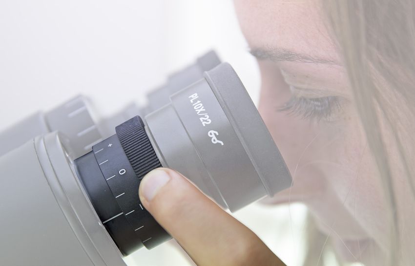
Overview

                    LED
                                                PHASE
                    HOUSING
                                                CONTRAST
                                                SLIDER

                                                       TRINOCULAR       EYEPIECE
                                                       VIEWING
                                                       TUBE
                                                       (FIXED)
 CONDENSER

 FILTER
 HOLDER

                                                                                 DIOPTRIC
                                                                                 ADJUSTMENT
                                                                                 RING
                              GLASS STAGE
                              INSERT

   STAGE
                                                                    LIGHT PATH
                                                                    SELECTOR
                                                                    LEVER
OBJECTIVE

                                                               MICROSCOPE
                                                               BODY

                                     FINE FOCUS KNOB

TENSION                COARSE
ADJUSTMENT COLLAR      FOCUS KNOB

                                            5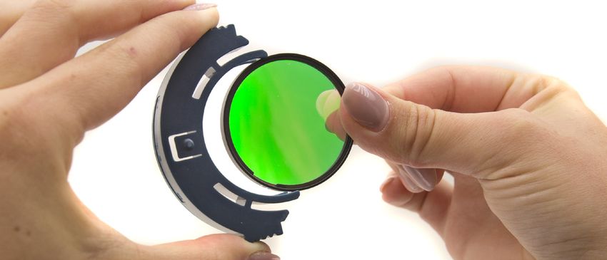
Installing the objectives
                                                          ②
1. Turning the coarse focusing knob ① till the
   nosepiece reaches its lowest position.
► For a safe transport, the nosepiece is
   placed in the lowest position and the
   tension adjustment collar ② is adjust-                     ①
   ed to the appropriate tension when the
                                                                  Fig.1
   microscope leaves the factory. (Fig.1)

2.   Screw the lowest magnification objective
     on to the turret from the right side, then
     turn the turret clockwise. Mount the other
     objectives in the same way, following the
     sequence from low to high.
►    Note: the objectives can also be in-
     stalled through the stage opening.
     (Fig.2)
►    Clean the objectives regularly. In inverted
     microscopes, the objectives are very sen-                    Fig.2
     sitive to dust.
►    To prevent dust and contamination from
     entering the microscope, cover all the un-
     used holes with dust caps ③. (Fig.3)
►    When operating, use the low magnification
     objective (10X) to search and focus the
     specimen, then switch to higher magnifica-
     tions.                                                         ③
►    When switching between objectives, slowly
     turn the nosepiece until it clicks. The click
     means that the objective is in the right posi-               Fig.3
     tion, in the center of the light path.

Installing the stage extension and
the mechanical stage (OPTIONAL)

The stage extension can be installed on either
side of the stage to enlarge the working sur-
face. The mechanical stage must be installed
on the side opposite the extension.
For right-handed operators, the mechanical                        Fig.4
stage is normally installed on the right side.

1. Installing the stage extension: Screw the
   bolts on to the extension, then mount the
   extension from below the stage. (Fig.4)
2. Installing the mechanical stage: As for the
   extension, the mechanical stage is fixed
   with two bolts under the stage. (Fig.5)

                                                                  Fig.5

                                                      6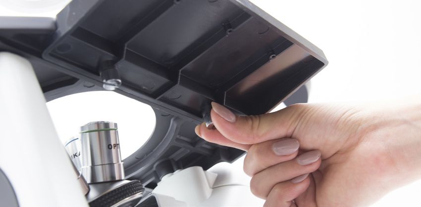
Installing the stage insert

1. When using the glass stage, make sure
   that the insert is horizontal.

2. Install the stage insert in the stage
   opening. (Fig.6)                                                Fig.6

Installing the eyepieces

Insert both eyepieces into the tubes of the
optical head. (Fig.7)                                              Fig.7

Installing the condenser illumination
unit and the LED housing

1.   Insert the condenser illumination unit into
     the bracket. (Fig.8)

2.   Turn the condenser illumination unit
     clockwise about 90°, with the “AS” mark
     of filter holder facing forwards. Align the
                                                           Fig.8   Fig.9
     screw of the condenser illumination unit
     and the hole of the holder, then screw
     the bolt in the hole with the supplied allen
     wrench. (Fig.9)

3.   Insert the connector plug into the
     connector jack.

4.   Push the LED housing gently into the
     holes of the illumination unit. (Fig.10)                      Fig.10

Installing the color filters

►     Remove the filter holder, then install the
      color filters you need. (Fig.11, Fig.12)
      Mount the color filter flat as shown in ①,
      verifying that they are not tilted.

►     If the color filter is tilted or otherwise
                                                                   Fig.11
      out of place ②, it may fall.

                                       ①
        ②
      The color filters can be stacked in the
      holder. This allows to install as many filters
      as needed, as long as the whole thickness
      is less than 11 mm.                                          Fig.12

                                                       7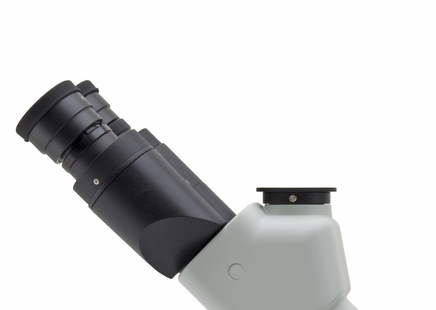
Installing the fluorescence

•   When using the epifluorescence, you can
    mount the anti-glow cap on the bottom of
    the condenser, in order to increase the
    contrast of the image. (Fig.13)
                                                         Fig.13

•   Unscrew the protection cover on the left
    side of the microscope, with the provided
    allen wrench. (Fig.14)

                                                         Fig.14

•   Slide the green filter inside the dovetail
    guide, after screwing the filter lever into
    the threaded hole of the filter. Mount
    the protection cover back in its position.
    (Fig.15)

                                                         Fig.15

•   On top of the filter lever, screw the terminal
    with the etched G. Repeat the same steps
    for the right side, mounting the Blue
    filterset. (Fig.16)

                                                         Fig.16

•   Connect the external power supply to the
    input jack on the rear. (Fig.17)

                                                         Fig.17

                                                     8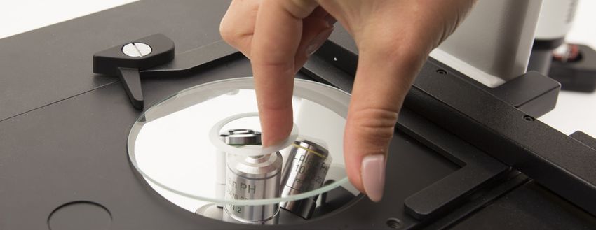
Using the microscope
 INITIAL SETUP

 Turning on the LED
 Connect the power, turn on the main switch ①.                                    ①                               Fig.18
 (Fig.18)
 Position ①: BF
 Position ②: Epifluorescence
 Adjusting the brightness
 Turn the brightness adjustment knob ② to
 increase and decrease the brightness. (Fig.19)

 Adjusting the tension                                                              ②                             Fig.19
 ► The coarse focusing knob ① is pre
     adjusted to a tight tension upon leav-
     ing the factory.                                                                              ②
 If the nosepiece drops down by itself, or the
 specimen defocuses while adjusting the fine
 focus knob ③, the coarse focus knob is too                                                              ③
 loose. Turning the tension adjustment collar ②
 in clockwise direction tightens the coarse fo-
 cus tension ①. Rotate in the opposite direction
 to decrease the tension. (Fig.20)                                                                ①               Fig.20

 STAGE (OPTIONAL)
                                                                         H793.1
                                                                         Holder for Petri diameter 38mm (H793.2 needed)
 Setting the specimen
 ► For the best image quality, use flasks,
      Petri dishes and slides with a 1.2 mm
      thickness.                                                         H793.2
 1. Place the proper insert for your specimen                            Holder for Terasaki and Petri diameter 65mm.
     (according to the table on the right) on the
     stage, and fix it with the stage clip.
 2. Turning the X and Y knobs, move the
     specimen to the required position. (Move-                           H793.3
     ment Range: 120 (width) × 78 (length)                               Holder for slide and Petri diameter 54mm.
     mm).

 Moving the specimen
 Move the specimen to the desired position by                            H793.4
 freehand or by turning the knobs of the me-                             Holder for 2+2 slides.
 chanical stage.
 ► When switching objectives, take care
      not to touch the adaptor plates with
      the objectives, as their weight may                                H793.6
      damage the front lens.                                             Holder for Utermöhl-Chamber (H793.3 needed).

                                                                         H793.7
                                                                         Load-bearing side extension for IT415.

                                    MSI792
                                    Mechanical stage for IT415 series.

                                                           9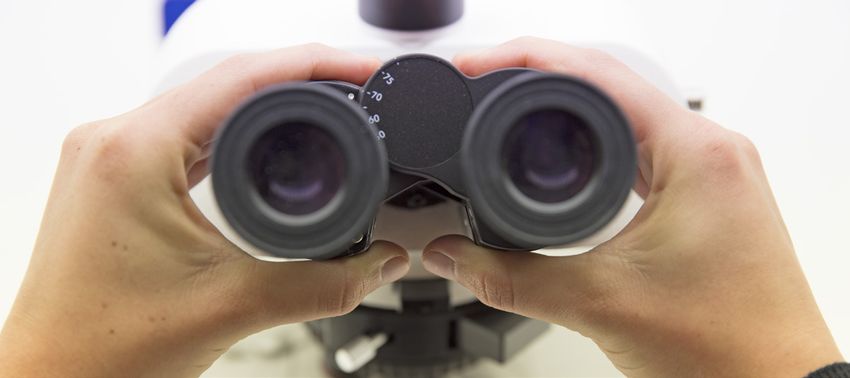
VIEWING TUBE

Dioptric adjustment                                                   ①
1.   Look into the right eyepiece with your right
     eye only, and focus on the specimen.
2.   Look into the left eyepiece with your left
     eye only. If the image is not sharp, use
     the dioptric adjustment ring ① to compen-
     sate. (Fig.21)

►    The adjustment range is ±5 diopter.
     The number indicated on the adjust-                                                                   Fig.21
     ment ring graduation should corre-
     spond to the operator’s dioptric cor-
     rection.

Adjusting the interpupillary distance

Observing with both eyes, hold the two eye-
                                                          ②
piece prism assemblies. Rotate them around
their common axis until the fields of view co-
incide.

►    The graduation on the interpupillary
     distance indicator ②, pointed by the
     spot “.” on the eyepiece holder, shows                                                                Fig.22
     the distance between the operator’s
     eyes. (Fig.22)

The range of the interpupillary distance is 48-
75mm.

Selecting the light path

Pull the light path selector lever ③ sideways
using your thumb, selecting the light path you              ③
need. (Fig.23)

                                                                                                           Fig.23

LIGHT PATH SELECTOR                             BRIGHTNESS                              APPLICATION
       LEVER
             In                    20% used for binocular observation, and   Binocular observation, television, and
                                     80% used for video or photography       micrography or video can be operated
                                                                                        simultaneously
            Out                             100% used for binocular                        Binocular
                                                 observation                              observation

                                                          10
ILLUMINATION UNIT
Using color filters
Selecting the appropriate color filters accord-
ing your need. (Fig.24)
You can stack a group of color filters in the fil-
Fig.24
ter holder, if you ensure that they are level and
that the whole thickness is less than 11mm.
Using the aperture diaphragm
70-80%
70-
① 80%
When in brightfield observation, the aperture
diaphragm controls the numerical aperture of
the illumination system. When the numerical
aperture of the objective and the aperture of
the illumination system match, the highest res-
30-20%
30-
olution is achieved. 20%
The aperture can be changed by moving the
aperture adjustment lever. ① is the image of Fig.25
the aperture diaphragm, ② is the edge of the ②
objective).
Generally, when observing a fully chromatic COLOR USE
specimen, you need to set the size of the con- FILTER
denser to 70-80% of the aperture of the objec-
tive. When observing unstained samples (e.g. Green Single contrast color filter used for phase
bacteria), start from 70% and slowly turn the contrast microscopy
aperture diaphragm lever clockwise. (Fig.25)
PHASE CONTRAST
① ② ③
Phase contrast slider
Adjustable phase slider.
● The light ring is pre-centered when the
microscope leaves the factory. It should
therefore need no further adjustment. If a
recentering is needed, it can be performed
via the two side bolts.
● The 4X/10X light ring ① must be used with
Fig.26
4X and 10X phase contrast objectives,
the 20x/40x light ring ② with the 20x and
40x and the opening ③ is used for bright
field. (Fig.26)
Installing the phase contrast slider
1. Insert the slider into the illumination
system, printed face up.
2. Pull the slider into the desired position, to
the click stop.
3. When in phase contrast observation, keep
the aperture diaphragm adjustment lever
on the “O” (open) position. (Fig.27) Fig.27
11Centering the ring
► Usually this operation is not needed. If
necessary, please proceed with the fol-
lowing steps:
1. Place a specimen on the stage and focus
it.
2. Take out the eyepiece from the tube with-
out the dioptric adjustment, and replace it Fig.28
with the centering telescope (CT). (Fig.28)
3. Check that the phase ring and the objective
correspond, and that both are steadily set
on a click stop.
4. Use the CT to focus on the light ring’s im-
age ① and the phase contrast ring’s image
②. If the light ring’s image is not sharp, ad-
just the CT’s eyepiece until you can see a
clear image of the light ring.
5. Adjust the bolts of the two centering holes
in the phase contrast slider using a screw-
driver until the light ring center and the
phase contrast ring center coincide.
6. The 10X and the 20X phase contrast objec- Fig.29
tives use the same ring on the phase con-
trast slider. The coincidence of the light ring
center and the phase contrast center must
be verified with both objectives.
(Fig.29; Fig.30)
► If the light ring is centered incorrectly,
①
the contrast will be severely impaired.
► The phase ring may need recentering
during and after observation of very
thick specimens.
► The phase ring may show an apparent
misalignment if the cover glass is not
flat.
② Fig.30
12MICROPHOTOGRAPHY
Installing the photography adapter
1. To activate the video port, pull the light
path selector lever to “In” position. (Fig.31)
2. Loosen the locking bolt ① on the trinocu-
lar viewing tube, and take out the dust cap
②.
3. Install the photography adapter into the
trinocular port according to its instructions,
and screw down the locking bolt ①. Fig.31
4. Attach the camera ring (if any) to the
adapter.
5. Attach the camera to the ring.
● Warning: for some cameras (mainly re-
flex) the ring is not included with the mi-
croscope, and it should be supplied by the
Camera
user.
● For the photography of dark specimens, Adapter
obscure the eyepieces and the viewfinder
with a dark cloth in order to reduce stray
light.
②
● The camera magnification can be calcu-
lated as objective magnification × camera ①
+ lens magnification.
► When shooting with a SLR, the mirror
movement may cause camera move-
ment. Please lift the mirror, use long
exposure times and use an extension Fig.32
cord. (Fig.32)
13Troubleshooting
Review the information in the table below to troubleshoot operating problems.
PROBLEM CAUSE SOLUTION
I. Optical Section:
1. The illumination is open, but The plug of the LED holder Connect them
the field of view is dark. is not connected to the il-
lumination set
The brightness is too low Adjust to a proper setting
Too many colour filters have Minimize the number of the filters
been stacked
2. The edge of the field of view The nosepiece is not in the Turn the nosepiece to a click stop
is vignetted or the brightness is correct position
asymmetric. The color filter is partially Insert the filter to full depth
inserted
The phase contrast slider is Move the slider to a click stop
not in the proper position
3. Dust and stains can be seen in There are stains and dust on Clean the specimen
the field of view. the specimen
There are stains and dust on Clean the eyepiece
the eyepiece
4. There is an apparent double The size of the aperture Open the aperture diaphragm
image. diaphragm is too small
5. Poor image quality: The nosepiece is not in the Turn the nosepiece to a click stop
The image is not sharp center of the light path
The contrast is not high The aperture diaphragm in Adjust the aperture diaphragm
The details are not clear the view of field is opened
The phase contrast is low. too much or too little
The lenses (condenser, Thoroughly clean all the optical system
objective, eyepieces are
culture dish) is dirty
In phase contrast observa- Use a sample holder whose bottom
tion, the bottom thickness thickness is less than 1.2mm
of the sample is more than
1.2mm
A bright field objective is Switch to a phase contrast objective
used for phase contrast
observation
The condenser ring is not Adjust the condenser ring to match the
aligned with the objective objective phase ring
phase ring
The light ring and/or the Adjust the bolts to center them
phase contrast ring is not
centered
The objective used is not Please use a compatible objective
compatible with the phase
ring
The phase contrast depends The sample holder is not flat. Move the
on the sample position sample around until a compatible area
is found.
146. One side of the image is out of The nosepiece is not in the Turn the nosepiece to a click stop
focus. center of the light path
The specimen is out of place Place the specimen flat on the stage.
(tilted)
The optical performance of Use a cover glass of better quality
the sample cover glass is
poor
II. Mechanical Section:
1.The coarse focus knob is hard The tension adjustment col- Loosen the tension adjustment collar
to turn. lar is too tight
2.The focus is unstable. The tension adjustment col- Tighten the tension adjustment collar
lar is too loose
III. Electric section
1. The LED doesn’t turn on. No power supply Check the power cord connection
2. The brightness is not enough The brightness adjustment Adjust the brightness
is low
3. The light blinks The power cord is poorly Check the power cord
connected
IV. Viewing tube assembly
3. The field of view of the two The interpupillar distance is Adjust the interpupillar distance
eyes is different not correct
The dioptric correction is not Adjust the dioptric correction
right
The viewing technique is not When look into the objective, do not
correct, and the operator is stare at the specimen but look at the
straining the eyesight whole field of view. Periodically, move
the eyes away to look at a distant ob-
ject, then back into the objective
V. Microphotography and video
1. The image is unfocused Incorrect focussing Adjusting the focus system as in the
present manual
2. The edge of the image is To some degree, it is inher- The problem can be minimized by a
unfocussed ent to the nature of achro- correct setting of the aperture dia-
matic objectives phragm
3. Bright patches appear on the Stray light is entering the Cover the eyepieces and the viewfind-
image microscope through the er with a dark cloth
eyepieces and through the
camera viewfinder
15Repair and maintenance
Microscopy environment
This microscope is recommended for use in a clean, dry and shock free environment with a temperature of
0-40°C and a maximum relative humidity of 85 % (non condensing). Use a dehumidifier if needed.
After using the microscope
The microscope should always be kept vertical when moving it so that no moving parts, such as the
eyepieces, fall out.
Never mishandle or impose unnecessary force on the microscope.
Never attempt to service the microscope yourself.
After use, turn down the illumination intensity control and turn the light off. Cover the microscope with included
the dust cover, and keep it in a dry and clean place.
Electrical safety precautions
Before plugging in the power supply, make sure that the supplying voltage of your region matches with the
operation voltage of the equipment and that the lamp switch is in off-position.
Users should observe all safety regulations of the region. The equipment has acquired the CE safety label.
However, users do have full responsibility to use this equipment safely.
Cleaning the optics
If the optical parts require cleaning first use compressed air.
If that is not sufficient use a soft lint-free cloth with water and a mild detergent.
And as a final option use the piece of cloth moistened with a 3:7 mixture of ethanol and ether.
Note: ethanol and ether are highly flammable liquids. Do not use them near a heat source, near sparks or
near electric equipment. Use these chemicals in a well ventilated room.
Remember to never wipe the surface of any optical items with your hands. Fingerprints can damage the op-
tics. Do not disassemble objectives or eyepieces in an attempt to clean them.
For the best results, use the VWR cleaning kit (see catalogue number below).
If you need to send the microscope to manufacturer for maintenance, please use the packaging if possible.
16List of accessories and spare parts
CAT. NO. DESCRIPTION
EYP780 Eyepiece EWF10x/22mm.
EYP781 Eyepiece micrometer EWF10x/22mm.
VWR005 26x76 mm micrometric slide. Range 1 mm, div. 0,01 mm.
OBJ782 Objective IOS LWD PLAN Achromatic 4x/0,10 (w.d. 22mm).
OBJ782.1 Objective IOS LWD PLAN Achromatic for phase contrast 4x/0.13 (w.d. 16.9mm).
OBJ783 Objective IOS LWD PLAN Achromatic for phase contrast 10x/0,25 (w.d. 7,94mm).
OBJ784 Objective IOS LWD PLAN Achromatic for phase contrast 20x/0,40 (w.d. 7,66mm).
OBJ785 Objective IOS LWD PLAN Achromatic for phase contrast 40x/0,60 (w.d. 3,71mm).
OBJ786 Objective IOS LWD PLAN Achromatic 60x/0,70 (w.d. 2,50mm).
OBJ801 Objective IOS LWD FLUOR PLAN Achromatic 10x/0,30 (w.d. 10mm)
OBJ802 Objective IOS LWD FLUOR PLAN Achromatic 20x/0,45 (w.d. 5,1mm)
OBJ803 Objective IOS LWD FLUOR PLAN Achromatic 40x/0,65 (w.d. 2,6mm)
OBJ804 Objective IOS LWD FLUOR PLAN Achromatic 60x/0,7
CCD788 Photo adapter for REFLEX camera with FULL FRAME sensor.
CCD789 Focusable C-Mount adapter for 1/3” sensor.
CCD891 Focusable C-Mount adapter for 1/2” sensor.
CCD789. 2 Focusable C-Mount adapter for 2/3” sensor.
PTA699 Universal adapter for CCD114, CCD115, M116, PTA173 and eyepiece cameras.
MSI792 Mechanical stage for IM-3 series
H793.1 Holder for Petri diameter 38mm (H793.2 needed), for IT414/ IT415/IT405 series.
H793.2 Holder for Terasaki and Petri diameter 65mm, for IT414/ IT415/IT405 series.
H793.3 Holder for slide and Petri diameter 54mm, for IT414/ IT415/IT405 series.
H793.4 Holder for 2+2 slides, for IT414/ IT415/IT405 series.
H793.6 Holder for Utermöhl-Chamber (H793.3 needed), for IT414/ IT415/IT405 series.
H793.7 Load-bearing side extension for IT415/IT405 series
PTA173 Photo adapter for APS-C and Full Frame Reflex cameras.
CCD114 C-Mount adapter for 1/2” sensor.
CCD115 C-Mount adapter for 1/3” sensor.
M116 C-Mount adapter for 2/3” sensor.
17Technical service
Web Resources
Visit the VWR’s website at www.vwr.com for:
• Complete technical service contact information
• Access to VWR’s Online Catalogue, and information about accessories and related products
• Additional product information and special offers
Contact us For information or technical assistance contact your local VWR representative or visit. www.
vwr.com.
Warranty
VWR International warrants that this product will be free from defects in material and workmanship for a
period of five (5) years from date of delivery. If a defect is present, VWR will, at its option and cost, repair,
replace, or refund the purchase price of this product to the customer, provided it is returned during the war-
ranty period. This warranty does not apply if the product has been damaged by accident, abuse, misuse, or
misapplication, or from ordinary wear and tear. If the required maintenance and inspection services are not
performed according to the manuals and any local regulations, such warranty turns invalid, except to the ex-
tent, the defect of the product is not due to such non-performance.
Items being returned must be insured by the customer against possible damage or loss. This warranty shall
be limited to the aforementioned remedies. IT IS EXPRESSLY AGREED THAT THIS WARRANTY WILL BE
IN LIEU OF ALL WARRANTIES OF FITNESS AND IN LIEU OF THE WARRANTY OF MERCHANTABILITY.
Compliance with local laws and regulations
The customer is responsible for applying for and obtaining the necessary regulatory approvals or other au-
thorizations necessary to run or use the Product in its local environment. VWR will not be held liable for any
related omission or for not obtaining the required approval or authorization, unless any refusal is due to a
defect of the product.
18Disposal
This equipment is marked with the crossed out wheeled bin symbol to indicate that this equipment must not
be disposed of with unsorted waste.
Instead it is your responsibility to correctly dispose of your equipment the end of its life cycle by handling it
over to an authorized facility for separate collection and recycling. It is also your responsibility to decontami-
nate the equipment in case of biological, chemical and/or radiological contamination, so as to protect from
health hazards the persons involved in the disposal and recycling of the equipment.
For more information about where you can drop off your waste equipment, please contact your local dealer
from whom you originally purchased this equipment.
By doing so, you will help to conserve natural and environmental resources and you will ensure that your
equipment is recycled in a manner that protects human health.
Thank you
19Australia Hungary Singapore
VWR International, Pty Ltd. VWR International Kft. VWR Singapore Pte Ltd
Unit 1/31 Archimedes Place Simon László u. 4. 18 Gul Drive
Murarrie, Queensland 4172 4034 Debrecen Singapore 629468
Tel.: 1300 727 696 Tel.: (52) 521-130 Tel.: +65 6505 0760
Fax: 1300 135 123 Fax: (52) 470-069 Fax: +65 6264 3780
E-mail: info@hu.vwr.com E-mail: sales@sg.vwr.com
Austria
VWR International GmbH India
Graumanngasse 7 VWR Lab Products Private Limited Spain
1150 Vienna 135/12, Brigade Towers, 2nd Floor VWR International Eurolab S.L.
Tel.: +43 1 97 002 0 Front wing, Brigade Road, C/ Tecnología 5-17
Fax: +43 1 97 002 600 Bengaluru, India – 560 025 A-7 Llinars Park
E-mail: info@at.vwr.com Tel.: +91-80-41117125/26 (Bengaluru) 08450 - Llinars del Vallès
Tel.: +91-2522-647911/922 (Mumbai) Barcelona
Belgium Fax: +91-80-41117120 Tel.: 902 222 897
VWR International bvba E-mail: vwr_india@vwr.com Fax: 902 430 657
Researchpark Haasrode 2020 E-mail: info@es.vwr.com
Geldenaaksebaan 464 Ireland / Northern Ireland
3001 Leuven VWR International Ltd / Sweden
Tel.: 016 385 011 VWR International (Northern Ireland) Ltd VWR International AB
Fax: 016 385 385 Orion Business Campus Fagerstagatan 18a
E-mail: customerservice@be.vwr.com Northwest Business Park 163 94 Stockholm
Ballycoolin Tel.: 08 621 34 00
China Dublin 15 Fax: 08 621 34 66
VWR International China Co., Ltd Tel.: 01 88 22 222 E-mail: kundservice@se.vwr.com
Rm.219, 2100 Dongming Road Fax: 01 88 22 333
Pudong New District E-mail: sales@ie.vwr.com Switzerland
Shanghai 200123 VWR International GmbH
Tel.: +86-21-5898 6888 Italy Lerzenstrasse 16/18
Fax: +86-21-5855 8801 VWR International PBI S.r.l. 8953 Dietikon
E-mail: info_china@vwr.com Via San Giusto 85 Tel.: 044 745 13 13
20153 Milano (MI) Fax: 044 745 13 10
Czech Republic Tel.: 02-3320311/02-487791 E-mail: info@ch.vwr.com
VWR International s. r. o. Fax: 800 152999/02-40090010
Veetee Business Park E-mail: info@it.vwr.com Turkey
Pražská 442 Pro Lab Laboratuar Teknolojileri Ltd.Şti.
CZ - 281 67 Stříbrná Skalice The Netherlands a VWR International Company
Tel.: +420 321 570 321 VWR International B.V. Orta Mah. Cemal Gürsel Caddesi
Fax: +420 321 570 320 Postbus 8198 Ördekcioglu Işmerkezi No.32/1
E-mail: info@cz.vwr.com 1005 AD Amsterdam 34896 Pendik - Istanbul
Tel.: 020 4808 400 Tel.: +90216 598 2900
Denmark Fax: 020 4808 480 Fax: +90216 598 2907
VWR - Bie & Berntsen E-mail: info@nl.vwr.com Email: info@pro-lab.com.tr
Transformervej 8
2730 Herlev New Zealand UK
Tel.: 43 86 87 88 Global Science - A VWR Company VWR International Ltd
Fax: 43 86 87 90 241 Bush Road Customer Service Centre
E-mail: info@dk.vwr.com Albany 0632, Auckland Hunter Boulevard - Magna Park
Tel.: 0800 734 100 Lutterworth
Finland Fax: 0800 999 002 Leicestershire
VWR International Oy E-mail: sales@globalscience.co.nz LE17 4XN
Valimotie 9 Tel.: 0800 22 33 44
00380 Helsinki Norway Fax: 01455 55 85 86
Tel.: 09 80 45 51 VWR International AS E-mail: uksales@uk.vwr.com
Fax: 09 80 45 52 00 Haavard Martinsens vei 30
E-mail: info@fi.vwr.com 0978 Oslo
Tel.: 02290
France Fax: 815 00 940
VWR International S.A.S. E-mail: info@no.vwr.com
Le Périgares – Bâtiment B GO TO VWR.COM FOR THE
201, rue Carnot Poland LATEST NEWS, SPECIAL OFFERS
94126 Fontenay-sous-Bois cedex VWR International Sp. z o.o.
Tel.: 0 825 02 30 30 (0,15 € TTC/min) Limbowa 5 AND DETAILS OF YOUR LOCAL
Fax: 0 825 02 30 35 (0,15 € TTC/min) 80-175 Gdansk VWR DISTRIBUTOR
E-mail: info@fr.vwr.com Tel.: 058 32 38 200 do 204
Fax. 058 32 38 205
Germany E-mail: info@pl.vwr.com
VWR International GmbH
Hilpertstraße 20a Portugal
D - 64295 Darmstadt VWR International -
Freecall: 0800 702 00 07 Material de Laboratório, Lda
Fax: 0180 570 22 22* Edifício Neopark
Email: info@de.vwr.com Av. Tomás Ribeiro, 43- 3 D
*0,14 €/Min. aus d. dt. Festnetz 2790-221 Carnaxide
Tel.: 21 3600 770
Fax: 21 3600 798/9
E-mail: info@pt.vwr.com
20VWR
Microscopio serie 400
MANUALE D’ISTRUZIONI
Modello European Catalogue Number
IT405FLD 630-2695
Versione: 1
Emesso il: 27, 01, 2017Indirizzo legale del produttore
Europa
VWR International bvba
Researchpark Haasrode 2020
Geldenaaksebaan 464
B-3001 Leuven
+ 32 16 385011
http://be.vwr.com
Origine della merce: ITALIA
Indice Contenuti
Avvertenze
Informazioni sulla sicurezza
Contenuto della confezione
Utilizzo previsto
Simboli e convenzioni
Apertura della confezione
Procedura d’installazione
Specifiche tecniche
Descrizione dello strumento
Istruzioni per l’uso
Risoluzione problemi
Riparazione e manutenzione
Accessori sostituibili e parti di ricambio
Assistenza tecnica
Garanzia
Conformità a leggi e normative locali
Smaltimento
22Avvertenza
Questo microscopio è uno strumento scientifico di alta precisione, progettato per durare a lungo con una
minima manutenzione; la realizzazione è secondo i migliori standar ottici e meccanici, per poter essere uti-
lizzato quotidianamente.
Vi ricordiamo che questo manuale contiene informazioni importanti per la sicurezza e per la manutenzione
dello strumento, e deve quindi essere messo a disposizione di coloro che lo utilizzeranno.
Decliniamo ogni responsabilità derivante da un utilizzo dello strumento non indicato nel presente manuale.
Informazioni sulla sicurezza
Per evitare shock elettrici
Prima di collegare il cavo di alimentazione alla presa elettrica, assicurarsi che il voltaggio della rete locale
coincida con il voltaggio dello strumento e che l’interruttore dell’illuminazione sia nella posizione “Off”.
Gli utenti dovranno seguire tutte le norme di sicurezza locali. Lo strumento è certificato CE.
In ogni caso, gli utilizzatori sono gli unici responsabili per un utilizzo sicuro dello strumento.
Per l’utilizzo in sicurezza dello strumento è importante attenersi alle seguenti istruzioni e leggere il manuale
in tutte le sue parti.
Contenuto della confezione
①
②
⑪
④
⑩
③ ⑤ ⑧
⑨
⑥ ⑦
① Base del microscopio ⑦ Inserto portapreparati in vetro
② Condensatore ⑧ Filtri fluorescenza
③ Alloggiamento LED ⑨ Obiettivi
④ Coperchi di protezione filtri ⑩ Oculari
⑤ Tappo antiriflesso ⑪ Cavo di alimentazione
⑥ Filter holder
23Disimballagio
Il microscopio è riposto in un imballo di polistirolo espanso. Rimuovere il nastro adesivo dal collo ed aprire la
parte superiore dell’imballo. Fare attenzione a non far cadere le parti ottiche (obiettivi e oculari) nell’estrarre il
microscopio dalla scatola per evitare che vengano danneggiati. Utilizzare entrambe le mani (una intorno allo
stativo e una alla base), sfilare il microscopio dal contenitore e appoggiarlo su un piano stabile.
Utilizzo previsto
Solo per ricerca. Non è previsto alcun utilizzo di questo strumento per uso diagnostico.
Simboli e convenzioni
La seguente tabella riporta i simboli utilizzati in questo manuale.
PERICOLO
Questo simbolo indica un rischio potenziale ed avverte di procedere
con cautela.
Specifiche del prodotto
Testa
Testata di osservazione trinoculare, inclinata a 45°.
Oculari
Oculari a grande campo EWF10X/22 con indice di campo 22.
Nosepiece
Quintuple
Obiettivi
IOS PLAN LWD 10xPh, 20xPh, 40xPh
Tavolino
Tavolino fisso, dimensioni 250x160 mm
Messa a Fuoco
Sistema di messa a fuoco macro e micrometrica
Condensatore
Condensatore LWD, A.N. 0.30, distanza di lavoro 72 mm.
Illuminator
Luce trasmessa:
Sorgente luminosa di tipo P-LED8 con LED bianco 8W.
Luce riflessa:
LED ad alta efficienza, 18W.
Condensatore
Epi-fluorescenza:
Filtri blu e verdi
Campo luminoso
Filtro verdi
24Descrizione dello strumento
ALLOGGIAMENTO
SLIDER PER
LED
CONTRASTO
DI FASE
OCULARI
TUBO DI USCITA
TRINOCULARE
CONDENSATORE
PORTA-FILTRI
ANELLO DI
INSERTO REGOLAZIONE
PORTAPREPARATI DIOTTRICA
IN VETRO
TAVOLINO
SELEZIONATORE
PERCORSO LUMINOSO
OBIETTIVI
BASE DEL
MICROSCOPIO
ANELLO DI REGOLAZIONE
DELLA TENSIONE
MANOPOLA DI
REGOLAZIONE
DELLA MESSA A MANOPOLA DI
FUOCO REGOLAZIONE DELLA
MICROMETRICA MESSA A FUOCO
MACROMETRICA
25Installazione degli obiettivi
②
1. Ruotare la manopola di regolazione macro-
metrica ① finché la torretta portaobiettivi si
trova nella posizione più bassa.
► Per garantire la sicurezza durante il tra-
sporto, prima della spedizione la torret-
ta viene messa nella posizione più bas- ①
sa e si sistema l’anello di regolazione
della tensione ② nella tensione appro- Fig.1
priata. (Fig.1)
2. Avvitare l’obiettivo con minore potere di in-
grandimento sulla torretta dal lato destro,
quindi ruotare la torretta in senso orario.
Montare gli altri obiettivi nello stesso modo,
dall’obiettivo con potere di ingrandimento
minore a quello maggiore.
► Nota: è possibile installare gli obiettivi
anche attraverso l’apertura del piano
portapreparati. (Fig.2)
► Tenere gli obiettivi puliti. Nei microscopi ro-
vesciati gli obiettivi sono molto sensibili alla Fig.2
polvere.
► Per evitare polvere e contaminazioni, co-
prire tutti i fori non utilizzati con gli appositi
tappi antipolvere ③. (Fig.3)
► Durante l’uso, servirsi degli obiettivi con
minor potere di ingrandimento (10X) per
guardare e mettere a fuoco i preparati,
quindi aumentare il potere di ingrandimen-
to. ③
► Per passare da un obiettivo a un altro,
ruotare lentamente il revolver finché non
scatta. Lo scatto avverte che l’obiettivo è in
posizione corretta, al centro del percorso Fig.3
luminoso.
Installazione del prolungamento del
piano e del tavolo traslatore (OPZIONALE)
Il prolungamento può essere montato su
entrambi i lati del piano portapreparati per
aumentare la superficie
di lavoro. Il tavolo traslatore va installato sul
lato opposto a quello del prolungamento. Fig.4
Per operatori destrimani, solitamente il tavolo
traslatore si installa sul lato destro.
1. Installazione del prolungamento del piano:
Anzitutto avvitare i bulloni al prolungamento,
quindi montare il prolungamento da sotto il
piano portapreparati. (Fig.4)
2. Installazione del tavolo traslatore: Come
per il prolungamento, anche il tavolo
traslatore è fissato da due bulloni sotto il
piano. (Fig.5)
Fig.5
26Installazione dell’inserto in vetro
1. Assicurarsi che il piano portapreparati sia
perfettamente orizzontale quando si usa il
piano in vetro.
2. Inserire l’inserto in vetro nell’apertura del
piano. (Fig.6) Fig.6
Installazione degli oculari
Togliere il tappo ai tubi portaoculari, inserire gli
oculari nei tubi. (Fig.7)
Fig.7
Installazione del gruppo
condensatore-illuminatore e
dell’alloggiamento LED
1. Inserire il gruppo condensatore-
illuminatore nell’apposito braccio. (Fig.8)
2. Ruotare il gruppo in senso orario di circa
90°: il marchio “AS” del portafiltri deve Fig.8 Fig.9
essere rivolto in avanti. Allineare la vite del
gruppo condensatore-illuminatore con il
foro nel portafiltri, quindi avvitare il bullone
nel foro servendosi dell’apposita chiave
esagonale inclusa nel kit. (Fig.9)
3. Inserire il cavo di alimentazione nel
connettore jack.
4. Inserire il portalampada spingendolo
con molta cura nei fori del gruppo di Fig.10
illuminazione. (Fig.10)
Installazione dei filtri cromatici
► Togliere il portafiltro, quindi inserire
il filtro cromatico desiderato. (Fig.11,
Fig.12)
Il filtro cromatico va montato piano come in
figura ①, verificare che non sia inclinato.
Fig.11
► Se il filtro cromatico è inclinato o
comunque fuori posto ②, rischia di
cadere.
①
②
I filtri cromatici possono essere sovrapposti
nel portafiltri, permettendo così di inserire
tutti i filtri necessari finché lo spessore
resta inferiore a 11 mm. Fig.12
27Installazione fluorescenza
• Quando si utilizza l’epifluorescenza, po-
tete montare il tappo anti-riflesso sulla
parte inferiore del condensatore, in modo
da aumentare il contrasto dell’immagine.
(Fig.13)
Fig.13
• Svitare il coperchio di protezione alla sini-
stra dello stativo, con la chiave a brugola
fornita. (Fig.14)
Fig.14
• Fare scorrere il portafiltro verde lungo
la guida a coda di rondine, dopo aver
avvitato l’astina sul portafiltro. Rimontare il
coperchio di protezione. (Fig.15)
Fig.15
• Avvitare sull’estremità dell’astina il
terminale con la scritta “G” incisa. Ripetere
i medesimi passi sulla parte destra per il
filtro blu. (Fig.16)
Fig.16
• Collegare l’alimentatore esterno al jack di
ingresso posto sul retro. (Fig.17)
Fig.17
28Istruzioni per l’uso
SETUP INIZIALE
Accensione dell’illuminazione
Collegare l’alimentazione, quindi accendere ① Fig.18
l’interruttore ①. (Fig.18)
Regolazione della luminosità
Ruotare l’apposita manopola per aumentare o
diminuire la luminosità ②. (Fig.19)
Regolazione della tensione
► La manopola di regolazione macrome-
trica ① è pre-regolata sulla tensione
② Fig.19
massima prima della spedizione.
Se la torretta portaoculari cade da sola oppure
②
il preparato perde la messa a fuoco durante la
regolazione micrometrica ③, significa che la
manopola di regolazione macrometrica è trop-
po allentata. Ruotando l’anello di regolazione
③
della tensione ② in senso orario permette di
stringere la manopola della tensione macro-
metrica ①. Per allentare quest’ultima ruotare
in senso contrario. (Fig.20)
① Fig.20
PIANO PORTAPREPARATI (OPZIONALE)
H793.1
Inserimento del preparato nserto per Petri diametro 38mm (H793.2 richiesto)
► Per ottenere la migliore qualità
delle immagini, si consiglia l’uso di
beute, capsule Petri e vetrini con uno H793.2
spessore di 1.2 mm. Inserto per Terasaki e Petri diamtero 65mm.
1. Posizionare l’inserto appropriato per il
vostro campione (seguendo la tabella di
fianco) sul tavolino, e fissarlo tramite la
pinzetta a molla.
2. Ruotando le manopole X e Y (6,7), H793.3
muovere il preparato finché non si trova la Inserto per vetrino e Petri diametro 54mm.
posizione giusta. (range di spostamento:
120 (larghezza) × 78 (lunghezza) mm).
Spostamento del preparato H793.4
Si può sistemare il preparato nella posizione Inserto per 2+2 vetrini.
desiderata a mano oppure operando sui
comandi coassiali del tavolo traslatore.
► Nel cambiare gli obiettivi, fare
attenzione a non toccare i piani
adattatori con gli obiettivi, in quanto H793.6
il loro peso potrebbe danneggiare la Inserto per Utermöhl-Chamber (H793.3 richiesto).
lente frontale.
H793.7
Estensione laterale portante per IT415 serie.
MSI792
Tavolino traslatore per IT415 serie.
29OCULARI
Compensazione diottrica ①
1. Osservare e mettere a fuoco il preparato
guardando con l’occhio destro attraverso
l’oculare destro.
2. Ora guardare attraverso l’oculare sini-
stro con l’occhio sinistro. Se l’immagine
non è nitida, agire sulla compensazione
diottrica utilizzando l’apposito anello ①.
(Fig.21)
Fig.21
► Il range di compensazione è di ±5 diot-
trie. Il numero indicato sulla scala pre-
sente sull’anello di compensazione
dovrebbe corrispondere alla correzio-
ne diottrica dell’operatore
②
Regolazione della distanza interpupillare
Osservando con entrambi gli occhi, sostenere
il gruppo di oculari. Ruotare questi lungo l’as-
se comune fino ad ottenere un unico campo
visivo.
► La scala graduata sull’indicatore della Fig.22
distanza interpupillare ②, indicata dal
puntino “.” sul porta-oculare, mostra
la distanza interpupillare dell’operato-
re. (Fig.22)
Il range della distanza interpupillare è pari a
48-75mm.
Selezione del percorso luminoso
③
Con il pollice, spostare la levetta di selezio-
ne del percorso luminoso ③ di lato: in questo
modo è possibile selezionare il percorso lumi-
noso desiderato. (Fig.23)
Fig.23
LEVETTA DI SELEZIONE LUMINOSITÀ APPLICAZIONE
PERCORSO LUMINOSO
In 20% usato per osservazione binoculare Osservazione binoculare, televisione e
e 80% usato per video o fotografia micrografia oppure video (possibilità di
osservazione simultanea)
Out 100% usato per osservazione Osservazione binoculare
binoculare
30GRUPPO ILLUMINATORE
Utilizzo filtri cromatici
Scegliere i filtri cromatici a seconda delle
proprie esigenze. (Fig.24)
Nel portafiltri si possono ammucchiare una
serie di filtri purché siano disposti piani e lo Fig.24
spessore totale sia inferiore a 11mm.
Utilizzo del diaframma di apertura 70-80%
70-
Nelle osservazioni in campo chiaro, il ① 80%
diaframma di apertura controlla l’apertura
numerica dell’illuminatore. Per ottenere la
risoluzione migliore, l’apertura numerica
dell’obiettivo e l’apertura dell’illuminatore
devono coincidere. 30-20%
30-
Il diaframma di apertura appare come in
figura. T L’apertura può essere variata 20%
operando sull’apposita levetta di regolazione
Fig.25
① è l’immagine del diaframma di apertura ② è
il bordo dell’obiettivo.
②
Generalmente, osservando un preparato
completamente cromatico, sarà necessario COLOR USE
impostare le dimensioni FILTER
del condensatore su 70-80% dell’apertura
dell’obiettivo. Per l’osservazione di campioni Verde Filtro cromatico utilizzato per microscopia a
non tinti invece (per contrasto di fase
es. batteri), si cominci da 70% e si ruoti
lentamente la levetta del diaframma di apertura
in senso orario. (Fig.25)
CONTRASTO DI FASE
Slider per contrasto di fase
① ② ③
Slider per contrasto di fase regolabile.
● L’anello di supporto per l’illuminatore
viene precentrato presso il costruttore
prima della spedizione del microscopio,
dunque non dovrebbe richiedere ulteriori
regolazioni. Nel caso in cui fosse
necessario, comunque, si agisca sulle
due viti laterali.
● L’anello di fase 4x/10x ① deve essere
utilizzato gli obiettivi 4x e 10x per contrato
di fase, l’anello di fase 20x/40x ② con gli Fig.26
obiettivi 20x e 40x e la posizione libera ③
è usata per il campo chiaro. (Fig.26)
Installazione dello slider per contrasto di
fase
1. Inserire lo slider nel gruppo illuminatore, la
parte stampata verso l’alto.
2. Spingere lo slider nella posizione
desiderata finché con si blocca con un
click.
3. Nelle osservazioni in contrasto di fase,
tenere la levetta di regolazione del
diaframma di apertura sulla posizione “O”
(open/aperto). (Fig.27) Fig.27
31ALLINEAMENTO DEI DIAFRAMMI
► Solitamente non è necessario effettuare
questa operazione. Nel caso lo fosse,
seguire la procedura descritta di
seguito:
1. Posizionare un preparato sul piano e
metterlo a fuoco.
2. Estrarre l’oculare dal tubo senza Fig.28
compensazione diottrica e sostituirlo con il
telescopio di centratura (CT). (Fig.28)
3. Verificare che l’anello di fase e l’obiettivo
corrispondano e che entrambi siano fissi in
posizione di blocco.
4. Con il CT mettere a fuoco l’immagine
del cerchio luminoso ① e l’immagine
dell’anello per contrasto di fase ②. Se
l’immagine del cerchio luminoso non è
nitida, regolare l’oculare del CT fino ad
ottenere un’immagine nitida del cerchio
luminoso.
5. Regolare le viti dei due fori di centratura
sullo slider per contrasto di fase con un Fig.29
cacciavite fino a far coincidere il cerchio
luminoso con l’anello di contrasto di fase.
6. Gli obiettivi per contrasto di fase 10X
e 20X utilizzano lo stesso anello sullo
slider. Si raccomanda quindi di verificare ①
la centratura dei diaframmi di fase con
entrambi gli obiettivi.
(Fig.29; Fig.30)
► Se diaframma non è centrato
correttamente, il contrasto potrebbe
risultarne fortemente indebolito.
► L’anello di fase potrebbe richiedere
una ri-centratura durante e dopo
l’osservazione di preparati dallo
② Fig.30
spessore piuttosto consistente.
► L’anello di fase potrebbe mostrare
un apparente disallineamento nel
caso in cui il vetrino non sia collocato
perfettamente piano.
32MICROFOTOGRAFIA
Installazione dell’adattatore fotografico
1. Per attivare l’acquisizione video, tirare
verso l’esterno la levetta di selezione del
percorso luminoso. (Fig.31)
2. Svitare il bullone di bloccaggio ① sul tubo
trinoculare e rimuovere il tappo antipolvere Fig.31
②.
3. Installare l’adattatore foto nella porta
trinoculare seguendo le istruzioni, quindi
riavvitate il bullone di bloccaggio ①.
4. Collegare l’anello della macchina (se
presente) all’adattatore. Camera
5. Collegare la macchina all’anello.
● Attenzione: per alcune macchine
Adapter
(soprattutto le reflex) l’anello non è fornito
insieme al microscopio, ma sarà l’utente a
doverlo recuperare. ②
● Per la fotografia di preparati scuri, oscurare
gli oculari e il mirino con un panno scuro ①
per limitare la luce diffusa.
● Per misurare l’ingrandimento della
macchina fotografica calcolare
ingrandimento dell’obiettivo ×
ingrandimento macchina fotografica x Fig.32
ingrandimento lente.
► Se si utilizza una macchina SLR, il
movimento dello specchio potrebbe far
vibrare la macchina.
Si consiglia di sollevare lo specchio,
di usare tempi di esposizione lunghi e
uno scatto remoto. (Fig.32)
33Risoluzione problemi
Consultare le informazioni riportate nella tabella sottostante per risolvere eventuali problemi operativi.
PROBLEMA CAUSA SOLUZIONE
I. I. Problemi ottici:
1. L’illuminatore è acceso, ma il cam- La spina dell’alloggiamento Collegare l’alloggiamento LED al gruppo
po visivo è scuro LED non è collegata al gruppo illuminatore
illuminatore
La luminosità è troppo bassa Regolare la luminosità
Sono stati sovrapposti troppi Ridurre il numero di filtri sovrapposti
filtri cromatici
2. Il bordo del campo visivo è sfuma- Il revolver portaobiettivi non si Ruotare il revolver finché non si blocca con
to oppure la luminosità è asimmetrica trova nella posizione corretta un click
Il filtro cromatico è inserito solo Inserire il filtro fino in fondo
parzialmente
Lo slider per contrasto di fase Spostare lo slider finché non si blocca con
non si trova nella posizione un click
corretta
3. Nel campo visivo si vedono polve- Sul preparato ci sono polvere e Pulire il vetrino con preparato
re e macchie macchie
Sull’oculare ci sono polvere e Pulire l’oculare
macchie
4. L’immagine appare doppia Il diaframma di apertura è trop- Aprire il diaframma di apertura
po chiuso
5. La qualità delle immagini è scarsa: Il revolver non si trova al centro Ruotare il revolver finché non si blocca con
L’immagine non è nitida; del percorso luminoso un click
Il contrasto non è alto; Il diaframma di apertura nel Regolare il diaframma di apertura
I dettagli non sono nitidi; campo visivo è troppo aperto
Il contrasto di fase è basso. oppure troppo chiuso
Le lenti (condensatore, obietti- Pulire accuratamente tutte le componenti
vi, oculari e piastre di coltura) ottiche
sono sporche
Per osservazioni in contrasto di Utilizzare un portapreparato con fondo
fase, lo spessore del fondo del spesso meno di 1.2mm
campione non deve superare i
1.2 mm
Si utilizza un obiettivo per Cambiare l’obiettivo e usarne uno per con-
osservazione in campo chiaro trasto di fase
anziché per contrasto di fase
L’anello condensatore non è Regolare l’anello condensatore fino ad
allineato all’anello dell’obiettivo ottenere l’allineamento
di fase
Il cerchio luminoso e/o l’anel- Operare sui bulloni per ottenere la
lo di contrasto di fase non è centratura
centrato
L’obiettivo usato non è Utilizzare un obiettivo compatibile
compatibile con l’anello di fase
Il contrasto di fase dipende Il portapreparati non è piano. Spostare il
dalla posizione del campione campione fino a trovare la posizione ideale.
346. Un lato dell’immagine non è a Il revolver non è al centro del Ruotare il revolver finché non si blocca con
fuoco percorso luminoso un click
Il preparato non si trova nella Posizionare il preparato orizzontalmente
posizione corretta (es. inclinato) sul piano
La qualità ottica del vetrino Utilizzare un vetrino di migliore qualità
portaprepatato è scarsa
II. Problemi meccanici
1. La manopola macrometrica è diffi- La manopola macrometrica è La manopola macrometrica è difficile da
cile da ruotare difficile da ruotare ruotare
2. La messa a fuoco è instabile La messa a fuoco è instabile La messa a fuoco è instabile
III. Problemi elettrici
1. Il LED non si accende Lo strumento non viene Verificare il collegamento del cavo di
alimentato alimentazione
2. La luminosità è La luminosità è regolata bassa Regolare la luminosità
insufficiente
3. La luce lampeggia Il cavo di alimentazione non è Verificare il collegamento del cavo
collegato bene
IV. Montaggio oculari
Il campo visivo è diverso per ciascun La distanza interpupillare non è Regolare la distanza interpupillare
occhio. corretta
La correzione diottrica non è Regolare la correzione diottrica
giusta
La tecnica di visione non è Quando guarda il campione non focalizzi
corretta, e l’operatore sforza la lo sguardo in un unico punto ma guardi
vista l’intero campo visivo a disposizione. Perio-
dicamente distolga lo sguardo e guardi un
punto distante, dopodichè torni ad analiz-
zare il campione.
V. Microfotografia e acquisizione video
1. L’immagine non è messa a fuoco L’immagine non è messa a L’immagine non è messa a fuoco
fuoco
2. Il bordo dell’immagine non è a In un certo grado ciò è insi- Per ridurre il problema al minimo, imposta-
fuoco to nella natura degli obiettivi re il diaframma di apertura nella posizione
acromatici migliore
3. Sull’immagine compaiono delle Nel microscopio entra della Coprire gli oculari e il mirino con un panno
macchie chiare luce diffusa attraverso gli ocula- scuro
ri oppure il mirino della macchi-
na fotografica / telecamera
35Riparazione e manutenzione
Ambiente d’utilizzo
Si consiglia d’utilizzare questo microscopio in un ambiente pulito, asciutto e non soggetto ad urti, ad una
temperatura tra 0° e 40°C ed con un’umidità relativa massima dell’ 85 % ( in assenza di condensazione). Se
necessario, utilizzare un deumidificatore.
Durante e dopo l’utilizzo
Il microscopio deve essere sempre tenuto in posizione verticale durante gli spostamenti, facendo attenzione
che le parti mobili, come gli oculari, non cadano.
Non maneggiare il microscopio in modo scorretto evitando ogni forzatura.
Non tentare di praticare la revisione dello strumento autonomamente.
Dopo l’utilizzo , spegnere immediatamente l’illuminazione, ricoprire il microscopio con la copertina anti polve-
re inclusa nella confezione, e riporre lo strumento in un luogo asciutto e pulito.
Precauzioni relative a strumenti elettrici
Prima di collegare la presa elettrica, assicurarsi che il voltaggio della rete elettrica locale coincida con il vol-
taggio dello strumento e che l’interruttore della lampada sia nella posizione “Off”.
Gli utenti dovranno seguire tutte le norme di sicurezza locali. Lo strumento è certificato CE.
In ogni caso, gli utilizzatori sono gli unici responsabili per un utilizzo sicuro dello strumento.
Pulizia delle ottiche
Se le parti ottiche necessitano di pulizia, per prima cosa ricorrere all’aria compressa.
Se ciò non fosse sufficiente, procedere all’utilizzo di un pezzo di stoffa morbida che non lasci residui, inumi-
dito con acqua o con un detergente delicato.
Infine, come ultima opzione, utilizzare un panno inumidito con una soluzione 3:7 di alcol etilico ed etere.
Attenzione: alcol etilico ed etere sono liquidi altamente infiammabili. Non utilizzarli in prossimità di fonti di
calore, scintille o attrezzature elettriche. Utilizzare questi prodotti chimici in ambienti ben ventilati.
Non strofinare la superficie di nessun componente ottico con le mani. Le impronte possono danneggiare
questi componenti.
Non smontare obbiettivi e oculari nel tentativo di pulirli.
Non smontare obbiettivi e oculari nel tentativo di pulirli.
Se si necessita di spedire il microscopio al produttore per la manutenzione, si prega di utilizzare l’im-
ballo originale.
36Elenco accessori e parti di ricambio
CAT. NO. DESCRIZIONE
EYP780 Oculare EWF10x/22mm.
EYP781 Oculare micrometrico EWF10x/22mm.
VWR005 Vetrino micrometrico per calibrazione software, 1mm/10um, 10mm/100um
OBJ782 Obiettivo IOS LWD PLAN Acromatico 4x/0,10 (w.d. 22mm).
OBJ782.1 Obiettivo IOS LWD PLAN Acromatico per contrasto di fase 4x/0.13 (w.d. 16.9mm).
OBJ783 Obiettivo IOS LWD PLAN Acromatico per contrasto di fase 10x/0,25 (w.d. 7,94mm).
OBJ784 Obiettivo IOS LWD PLAN Acromatico per contrasto di fase 20x/0,40 (w.d. 7,66mm).
OBJ785 Obiettivo IOS LWD PLAN Acromatico per contrasto di fase 40x/0,60 (w.d. 3,71mm).
OBJ786 Obiettivo IOS LWD PLAN Acromatico 60x/0,70 (w.d. 2,50mm).
OBJ801 Obiettivo IOS LWD FLUOR PLAN acromatico 10x/0,30 (w.d. 10mm)
OBJ802 Obiettivo IOS LWD FLUOR PLAN acromatico 20x/0,45 (w.d. 5,1mm)
OBJ803 Obiettivo IOS LWD FLUOR PLAN acromatico 40x/0,65 (w.d. 2,6mm)
OBJ804 Obiettivo IOS LWD FLUOR PLAN acromatico 60x/0,75
CCD788 Adattatore fotografico per macchine fotografiche REFLEX con sensore FULL FRAME.
CCD789 Adattatore fochettabile C-Mount per sensore 1/3”.
CCD891 Adattatore fochettabile C-Mount per sensore 1/2”.
CCD789. 2 Adattatore fochettabile C-Mount per sensore 2/3”.
PTA699 Adattatore universale per CCD114, CCD115, M116, PTA173 telecamera da oculare.
MSI792 Tavolino traslatore per IT414
H793.1 Inserto per Petri diametro 38mm (H793.2 richiesto), per le serie IT414/IT415/IT405.
H793.2 Inserto per Terasaki e Petri diamtero 65mm, per le serie IT414/IT415/IT405.
H793.3 Inserto per vetrino e Petri diametro 54mm, per le serie IT414/IT415/IT405.
H793.4 Inserto per 2+2 vetrini, per le serie IT414/IT415/IT405.
H793.6 Inserto per Utermöhl-Chamber (H793.3 richiesto), per le serie IT414/IT415/IT405.
H793.7 Estensione laterale portante per serie IT415/IT405.
PTA173 Estensione laterale portante per serie IT414.
CCD114 Adattatore C-Mount per sensore 1/2”.
CCD115 Adattatore C-Mount per sensore 1/3”.
M116 Adattatore C-Mount per sensore 2/3”.
37Assistenza tecnica
Risorse sul web
Visitare il sito web VWR all’indirizzo www.vwr.com per:
• Informazioni complete sui contatti dell’Assistenza tecnica
• Accesso al catalogo on-line VWR e ad ogni altra informazione relativa agli accessori e ai prodotti collegati
• Ulteriori informazioni sui prodotti e sulle promozioni
Contatti Per informazioni o assistenza tecnica, contattare i nostri uffici VWR o visitare il sito. www.vwr.com
Garanzia
VWR International garantisce per questo prodotto l’assenza da difetti nei materiali e di fabbricazione per un
periodo di cinque (5) anni dalla data di consegna. In caso contrario, VWR provvederà, a sua discrezione e a
proprie spese, alla riparazione, sostituzione o al rimborso del prezzo di acquisto del prodotto al cliente, pur-
ché venga restituito durante il periodo di garanzia. La presente garanzia non copre eventuali danni accidenta-
li o causati da abuso, uso o applicazione impropri o dal normale logorio dell’apparecchio. Qualora i servizi di
ispezione e manutenzione necessari non vengano eseguiti secondi i manuali e le eventuali normative locali,
tale garanzia risulta non valida, salvo nella misura in cui il difetto del prodotto non sia causato dalla mancata
prestazione dei suddetti servizi.
Il cliente dovrà assicurare le parti da restituire contro eventuali danni o perdite. La presente garanzia è limi-
tata ai suddetti rimedi. SI CONCORDA ESPRESSAMENTE CHE LA PRESENTE GARANZIA SOSTITUISCE
TUTTE LE GARANZIE DI IDONEITÀ E LA GARANZIA DI COMMERCIABILITÀ.
Conformità a leggi e normative locali
Il cliente è responsabile della richiesta e dell’ottenimento delle approvazioni normative necessarie o di altre
autorizzazioni necessarie per eseguire o utilizzare il prodotto nel suo ambiente locale. VWR non sarà ritenuta
responsabile delle relative omissioni o del mancato ottenimento dell’approvazione o autorizzazione necessa-
ria, a meno che l’eventuale rifiuto non sia dovuto a un difetto del prodotto
38You can also read