BodiLink Lateral Pelvic/Thigh Supports - OPERATION MANUAL - cloudfront.net
←
→
Page content transcription
If your browser does not render page correctly, please read the page content below

BodiLink® Lateral Pelvic/Thigh Supports
OPERATION MANUAL

Thank you for choosing BODILINK®

CONTACT INFORMATION                                         CONTENTS
                                                            Intended Use - Intended User                       2
    The Comfort Companies, LLC
1960 South Calhoun Road                                     Important Safety Information                       2-3
New Berlin, Wisconsin 53151 USA
                                                            Parts Detail                                       4
Phone:
U.S.A.: 800-736-0925                                        INSTALLATION
Outside the USA: 262-432-0830
                                                             Installation - Premium Pad to Mounting Hardware   5
Fax: 406-522-8563
Customer Support:                                            Installation - Basic Pad to Mounting Hardware     6
orders.comfort@permobil.com
                                                             Installation - Power Mount TT Hardware            7
permobilus.com
comfortcompany.com                                           Installation - Slot Mount TT Hardware             8

                                                             Installation - Extension Arm TT Hardware          9
     WARNING                                                 Installation - GT Slot Mount                      10
Indicates that not following the specified procedure
could lead to potentially hazardous conditions resulting     Installation - Extra Link(s) to GT Hardware       11
in serious injury.
                                                            ADJUSTMENT AND USE
     CAUTION                                                 Adjustment - Premium Pad                          12
Indicates that not following the specified procedure
could lead to potentially hazardous conditions resulting     Adjustment - Basic Pad                            13
in minor to moderate injury or damage to the equipment
or other property.                                           Adjustment - Power Mount TT Hardware              14

                                                             Adjustment - Slot Mount TT Hardware               15
INCIDENT REPORTING
                                                             Adjustment - Slot Mount GT Hardware               16
In the event of a serious incident or injury, contact
Customer Support.                                            Use - TT Hardware                                 17

                                                             Use - TT Hardware Release Lever                   18
PLEASE NOTE
                                                             Use - GT Hardware                                 18
Supplier: These instructions must be given to the user of
                                                            MAINTENANCE AND WARRANTY
this product.
Operator (Individual or Caregiver): Before using this        Cleaning                                          19
product, read the instructions and save for future
reference.                                                   Maintenance                                       20
Products may be covered by one or more U.S. and foreign      Warranty                                          20
patents and trademarks, including BodiLink®, Comfort-
Tek®, and Stretch-Air ®.
Quantum® is a registered trademark of Pride Mobility
Products Corporation.                                        Español                                           21
Quickie® is a registered trademark of Sunrise Medical        Français                                          41
ROVI® is a registered trademark of Shoprider Mobility
Products, Inc.                                               Português                                         61
Avid Rehab is a trademark of Merits Health Products.
GlideWear ® is a registered trademark of Tamarack
Habilitation Technologies, Inc.
Product information is changed as needed; current
product information is available at comfortcompany.com.
The Comfort Companies, LLC is a part of Permobil Seating
and Positioning.

© 2018, 2020 Permobil

REV 2020-03-04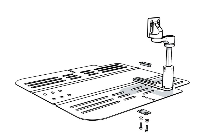
BodiLink Lateral Trunk Support Operation Manual

INTENDED USE - INTENDED USER

Intended Use
BodiLink® Lateral Pelvic/Thigh Support Premium Pads are constructed of molded foam with a track for adjustablity. A cover
is always required for use.
BodiLink® Lateral Pelvic/Thigh Support Basic Pads are constructed of a wooden base with T-nut inserts, bonded to a
structural foam pad. A cover is always required for use.

Intended User
BodiLink® lateral pelvic/thigh supports are intended for those with positioning and support needs as deemed necessary by
a qualified healthcare professional.
BodiLink® lateral pelvic/thigh supports offer a wide variety of available positions to accommodate user rehabilitation needs
and goals while allowing for function and comfort. The sizes available and range of adjustability fit pediatric to full grown
users and should be matched by the healthcare provider to suit the user needs. Adjustments or replacement components
may be necessary as changes in condition occur or to accommodate developments such as growth.

A clinician who is experienced in seating and positioning should determine whether the product is appropriate for the individual’s
particular seating needs. The product’s intended use statement alone should not be relied upon to make that determination.
The medical products featured in this document are intended to be only one part of an overall care regimen that includes all
seating and mobility equipment and therapeutic interventions. A clinician who is experienced in seating and positioning should
identify this care regimen after evaluating the individual’s physical needs and overall medical condition.
A clinician should also evaluate for visual, reading, and cognitive impairment to determine the need for caregiver assistance or the
need for other assistive technology, such as large-print instructions, to ensure proper product use.

IMPORTANT SAFETY INFORMATION

     WARNINGS: Follow These Instructions                                      WARNINGS: Use As Intended
-   User and Caregiver: Follow all instructions and                    -     During the first few hours of use, a healthcare
    safety information provided with the product and                         professional should be available to observe
    provided by the manufacturer of your wheelchair or                       skin condition and assess the likelihood of skin
    other accessories. The product should be installed                       breakdown. During regular use, periodically check
    and adjusted by a qualified and competent medical                        for skin discoloration and/or irritation. If there is any
    equipment provider or licensed healthcare professional.                  discoloration to skin/soft tissue, STOP USE immediately.
                                                                             If the discoloration does not disappear within 30 minutes
-   Permobil cannot be held responsible for damages
                                                                             of disuse, immediately consult a healthcare professional.
    or injury due to misuse of the product or failure to
    follow instructions provided in this manual. Contact               -     DO NOT place anything between the user and
    Customer Support if you require further assistance in                    the product. Additional materials may reduce the
    understanding cautions, warnings, or instructions for                    effectiveness of the product and increase risk factors for
    using or maintaining your product.                                       skin breakdown and instability.

     WARNINGS: Use As Intended                                                WARNINGS: Installation, Interference, Use
-   This product is designed for the intended user and                     - Never use the equipment unless all components are
    intended use only. Any modifications could potentially                   fully functional. Refer to the “Warranty” section in this
    endanger the user and cause discomfort or damage.                        manual.
-   Never use the equipment to maneuver a wheelchair or                -     ATTENTION! Before use: Check regularly to make sure
    anything that it is attached to. It is never to be used as a             the equipment is securely mounted to the wheelchair
    handle, lift, guide, or support, except as described in this             system and is properly adjusted, and check all hardware
    manual.                                                                  for wear, breakage, and tightness. Re-tighten any loose
                                                                             screws/bolts, referring to the instructions in this manual.
-   DO NOT use any BodiLink Supports to transfer in or out
                                                                             DO NOT continue to use the equipment if any part
    of the wheelchair. BodiLink Supports are not designed to
                                                                             cannot be tightened or is broken.
    support the full weight of the user.

                                                                   2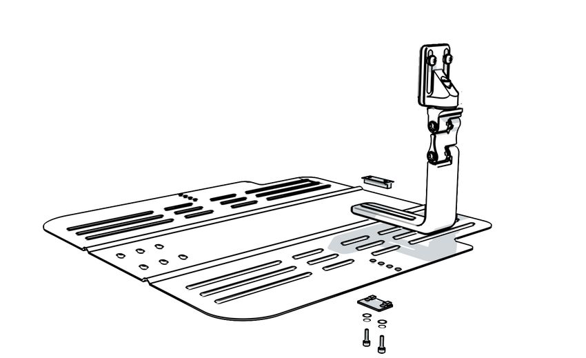
BodiLink Lateral Trunk Support Operation Manual

IMPORTANT SAFETY INFORMATION, CONTINUED

     WARNINGS: Installation, Interference, Use                             WARNINGS: Motor Vehicle Transportation
-   Unless otherwise specified, fasteners should be                    - Failure to pay attention to these warnings could result
    tightened to 9.6 Nm (85 lb-in).                                      in severe injury to the individual in the wheelchair or to
                                                                         others.
-   Ensure that the product does not interfere with any other
    wheelchair components. Interference could jeopardize               - Whenever possible, transfer out of your wheelchair
    effectiveness and user safety and cause damage. After                installed with BodiLink Supports and into a manufacturer-
    installation, slowly articulate the full range of power/             installed vehicle seat, and use the vehicle’s crash-tested
    recline / tilt, watching closely to make sure there is no            occupant restraint system.
    interference.                                                      - Children weighing less than 48½ lb. (22 kg) must be
-   DO NOT modify this product. Doing so will void its                   transferred into an appropriate child-restraint system
    warranty and may lead to personal injury or alter the                intended for use in motor vehicles.
    effectiveness of the product by increasing the risk factors        - ALWAYS store BodiLink Supports safely during transport
    for skin breakdown and/or instability.                               to avoid damage.
-   Installing alternate parts to your wheelchair may change           - If a BodiLink Support has been involved in an accident
    the structure and function of the equipment. To ensure               during transport, see the “Inspection” section in this
    stability during use, assess the need for additional safety          manual.
    features on the wheelchair, such as anti-tip bars or other
    available options.                                                 - The motor vehicle safety information in this operation
                                                                         manual applies to BodiLink Supports a) only when
-   Use caution when installing, adjusting, or removing                  correctly and securely installed, as instructed in this
    hardware, to avoid pinching or trapping fingers in                   manual; b) only with a wheelchair that complies with
    openings.                                                            the performance requirements of ISO 7176-19 and
-   Do not expose the product or components to high                      that is installed, used, and maintained according to the
    heat, open flames or hot ashes. Testing or certification             wheelchair manufacturer’s instructions.
    claims, including for flammability, may no longer apply            - The individual should be seated in an upright position and
    to this device when it is combined with other products               the wheelchair should face forward during transportation
    or materials. Check testing and certification claims for all         in a motor vehicle. BodiLink Supports have only been
    products used in combination with this device.                       crash tested on a wheelchair in the forward-facing
-   Metal components may become hot if exposed to high                   position, per the test information provided in this
    temperatures or cold if exposed to low temperatures.                 operation manual.
    Take appropriate precautions, especially when the                  - The wheelchair with a BodiLink Support must be used
    product will contact unprotected skin.                               with an effective wheelchair securement system and a
-   Avoid sharp objects.                                                 properly positioned, crash-tested pelvic- and shoulder-
                                                                         belt restraint, or a Wheelchair Tiedown and Occupant
-   Protect the product from blunt force shocks that may
                                                                         Restraint System (WTORS), following the manufacturer’s
    cause damage and/or breakage.
                                                                         instructions.
-   Always use the cover and base with any inserts as a
                                                                         The Comfort Company seating system with a back support
    complete assembly. Never use a cover other than one
                                                                         and accessories, including BodiLink Supports, installed on
    intended for your specific product and size.
                                                                         a surrogate wheelchair frame, has been dynamically tested
-   After hardware and pad positioning, make sure that the               by a third-party testing facility for use in a motor vehicle,
    gear teeth* on all link joints are properly aligned and              and meets all applicable performance criteria in Section 5.1
    engaged before final tightening. Failing to do so could              of ANSI/RESNA WC-4:2012 Section 20 “Wheelchair Seating
    cause wear on the teeth, leading to parts slipping out of            Systems for Use in Motor Vehicles” and in 5.1 of ISO 16840-4
    adjustment or hardware failure.                                      when tested with a surrogate seat.
-   Adding additional links to the hardware may reduce the
    overall strength.

*Gear Teeth Alignment

                                                                   3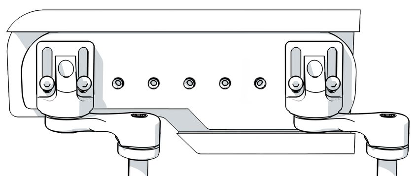
BodiLink Lateral Trunk Support Operation Manual

PARTS DETAIL

BodiLink® Lateral Pelvic/Thigh Support (LPTS) Hardware and Pads
                        TT Mounting Hardware                                                      GT Mounting Hardware
                Fixed and Removable Options Available                                     Fixed and Removable Options Available
      Slot Mount Hardware                      Power Mount Hardware                                          Slot Mount Hardware
                                                                  for:
                                                                  Permobil
                                                                  Quantum
                                                                  Quickie
                                                                  Rovi
                                                                  Avid Rehab

     available in small,                     available in small,
   medium, and large styles                medium, and large styles

                       Additional TT Hardware                                                         Additional GT Hardware
                      TT Long Extension Arm (4”)                                                     Additional GT Hardware Link

                                                                    LPTS Pads

           Premium Pads                       Basic Zero Elevation Pads                                      Basic Anti-Thrust Pads

      3.5”L x 4”D                      3”L x 4”D                                                 3”L x 4”D

      3.5”L x 8”D                      3”L x 5”D                                                 3”L x 5”D

     3.5”L x 12”D                      4”L x 4”D                                                 4”L x 4”D

      5.5”L x 6”D                      4”L x 6”D                                                 4”L x 6”D

                                       5”L x 7”D                                                 5”L x 7”D

                                       4”L x 8”D                                                 4”L x 8”D

                                      4”L x 10”D                                                4”L x 10”D

                                      4”L x 12”D                                                4”L x 12”D

                                      4”L x 14”D                                                4”L x 14”D

                                      4”L x 16”D                                                4”L x 16”D

                                                                          4
BodiLink Lateral Trunk Support Operation Manual

INSTALLATION - PREMIUM PAD TO MOUNTING HARDWARE

For any Premium pad and TT or GT hardware styles. All required tools are provided.

In some cases, the pad will come installed on the hardware.

1 Unzip and remove the cover and foam insert to gain access to the metal tracks (A) for hardware installation. Remove the
   plastic cap (if installed). Insert the two square nuts (B) into each of the two pad tracks (A).

2 Line up the bolts (C), safety washers (D), and slots on the mounting bracket (E) with square nuts (B) in track (A).
   Recommendation: If one hardware assembly is being used per pad, install the hardware closer to the center of the pad (depth).
   If two hardware assemblies are being assembled onto one pad, install one hardware assembly towards the front and one
   towards the rear of the pad.

3 Tighten the bolts (C) using the 5mm hex key. Reinstall the plastic cap (if provided).
4 Replace the cover by inserting the foam insert in the cover with the gripping side of the foam facing the support pad,
   and then add in the support pad and zip the cover closed.

                                                                                         A

                                                                                             E
                                                                                                  D

                                                         B

                                                                                                      C

                           3.5”L x 8”D Premium Pad and
                         Power Mount TT Hardware Shown

            3.5”L x 8”D Premium Pad with
          multiple sets of TT Hardware Shown

                                                                      5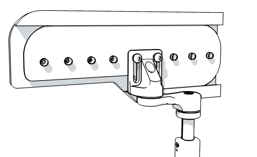
BodiLink Lateral Trunk Support Operation Manual

INSTALLATION - BASIC PAD TO MOUNTING HARDWARE

For any Basic pad and TT or GT hardware styles. All required tools are provided.

In some cases, the pad will come installed on the hardware. Each pad will have a series of T-nuts for hardware mounting.
The T-nuts are accessible through the slits in the cover (not pictured) for easy hardware mounting/removal.

1 Line up the screws (A), safety washers (B), and slots on the mounting bracket (C) with the desired T-nuts on pad (D).

   Recommendation: If one hardware assembly is being used per pad, install the hardware closer to the center of the pad (depth).
   If two hardware assemblies are being assembled onto one pad, install one hardware assembly towards the front and one
   towards the rear of the pad.

2 Tighten the pad mount screws (A) using the 5/32” hex key.
   Note: Do not fully tighten the screws if you are expecting to make further pad height adjustments while installing on the
   wheelchair.

                                     D                  C

                                                                                                                B
                                                                                                                       A

                     Zero Elevation Shape Pad and
                    Slot Mount TT Hardware Shown

            Anti-Thrust Shape Pad with
        multiple sets of TT Hardware Shown

                                                                   6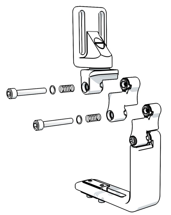
BodiLink Lateral Trunk Support Operation Manual

INSTALLATION - POWER MOUNT TT HARDWARE

Attaching TT hardware to the seat frame tracks: Permobil, Quantum, Quickie, Rovi, & Avid Rehab.
All required tools are provided.

1 Loosen the screws (A), connecting the hardware mounting block (B) to the double nut(s) (C) using the 5mm hex key.
   A gap between the mounting block and the double nut(s) is needed to slide into the seat frame track.

2 Attach the hardware mounting block (B) to the seat frame track by sliding the double nut(s) (C) inside of the seat
   frame track. Some wheelchairs may require temporary removal of a cap at the end of the track for this step. Slide the
   hardware to the general location on the seat frame track for the desired pad and hardware placement.

3 Do not fully tighten the screws (A). Continue with pad and hardware ADJUSTMENT and USE instructions in this manual.

 PW1 - Quantum                                                                                    Permobil PW2 Mounting Block and
                                                                                                      Seat Frame Track Shown

                                                                                           B
 PW2 - Permobil                                                       C

                                        Track Slots

 PW3 - Quickie

 PW4 - Rovi

                                                                                                  A

                                                                                   Removable Mounting
 PW5 - Avid                                                                          Bracket Shown

                                       Note: For removable hardware, the release
                                       lever can be installed towards the front or rear
                                       of the wheelchair, pointing either up or down,
                                       depending on user/caregiver preferences.

                                                                               Release Lever

                                                               7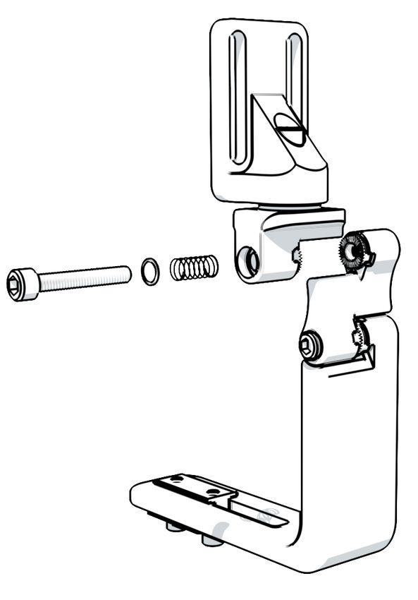
BodiLink Lateral Trunk Support Operation Manual
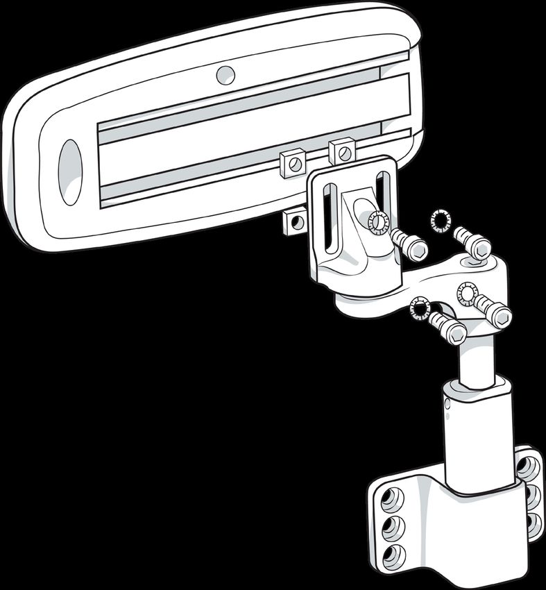
INSTALLATION - SLOT MOUNT TT HARDWARE
Attaching TT hardware to the Comfort Company solid seat support base. All required tools are provided.
1 Remove the screws (A), safety washers (B), flat
washers (C), double washer (D), and double nut (E)
from the TT hardware assembly (F), using the 5mm
hex key. Retain the fasteners for re-assembly.
2 Set the hardware assembly (F) on top of the seat
support base (G) in the desired location, making sure
the slot in the assembly base (F) aligns with two of the
slots on the seat support base (G), as shown.
For removable hardware, the silver release lever (not
pictured) is intended to face the front of the wheelchair.
E
3 Replace the double nut (E) in the top of the slot on (F).
4 Replace the screws (A), safety washers (B), flat
washers (C), and double washer (D) from below the F
seat support base (G). Note: The squares on (D) should
fit into the slots on (G). Do not fully tighten the screws to
allow further/final adjustments.
5 Continue with pad and hardware ADJUSTMENT and USE
instructions in this manual.
D
C
B
A
E
Fixed TT Hardware Shown
G
D
C F
A B
8BodiLink Lateral Trunk Support Operation Manual
INSTALLATION - EXTENSION ARM TT HARDWARE
For adding long extension arm to TT hardware. Required tools are shipped with TT mounting hardware.
1 Using the 5mm hex key, remove the long screw (A) and short screw (B) with safety washers (C) from both ends of
standard arm (D), included with the TT hardware assembly. Retain the fasteners for re-assembly.
2 Align the long extension arm (E) with the top of the hardware assembly (F), and replace the screw (B) and safety
washer (C) in the orientation shown.
3 Align the other end of the long extension arm (E) with the mounting bracket (G), and replace the screw (A) and safety
washer (C).
4 Continue with pad and hardware ADJUSTMENT and USE instructions in this manual.
A A
C C
B B
C C
G
E F
D
9BodiLink Lateral Trunk Support Operation Manual
INSTALLATION - GT SLOT MOUNT HARDWARE
Attaching GT hardware to the Comfort Company solid seat support base. All required tools are provided.
1 Remove the screws (A), safety washers (B), flat
washers (C), double washer (D), and double nut (E)
from the GT hardware assembly (F) using the 5mm hex
key. Retain the fasteners for re-assembly.
H
2 Set the hardware assembly (F) on top of the seat support
base (G) in the desired location, making sure the slot in
assembly base (F) aligns with two of the slots on the seat E
support base (G), as shown.
The screw heads (H) are intended to face forward on the
wheelchair for easier adjustments.
For removable hardware, the silver release knob (J) is
intended to face the front of the wheelchair for easier
access.
F
3 Replace the double nut (E) in the slot on (F).
4 Replace the screws (A), safety washers (B), flat
washers (C), and double washer (D) from below the
seat support base (G). Note: The squares on (D) should
fit into the slots on (G). Do not fully tighten screws to
allow further/final adjustments.
5 Continue with pad and hardware ADJUSTMENT and USE
instructions in this manual
D
C
J
B
A
E
Fixed GT Hardware Shown
G
D
F
C
A
B
10BodiLink Lateral Trunk Support Operation Manual
INSTALLATION - EXTRA LINK(S) TO GT HARDWARE
For adding extra hardware link(s) to GT hardware. All required tools are shipped with GT mounting hardware.
WARNING: Adding additional links to the hardware may reduce the overall strength.
*Gear Teeth Alignment
WARNING: Make sure that the teeth on all link joints are properly
aligned and engaged before final tightening. Failing to do so could cause wear
on the teeth, leading to parts slipping out of adjustment or hardware failure.
(GT Hardware only)
1 Remove the screw (A), safety washer (B), and spring (C) from the hardware joint using the 5mm hex key. Retain the
screw, washer and spring for the additional link.
Suggestion: If adding multiple links to one assembly, first line up the extra links and fasten with the screws, washers and springs
provided to create one extra link assembly.
2 Line up the extra link(s) (E) with link (D) and fasten with screw (F), washer (G), and spring (H) included with the extra link.
3 Line up the extra link(s) (E) with link (J) and fasten with screw (A), washer (B), and spring (C) that were retained in step 1.
4 Continue with pad and hardware ADJUSTMENT and USE instructions in this manual.
D
E
G H
F
J
B C C
A A B
Fixed GT Hardware Shown
11BodiLink Lateral Trunk Support Operation Manual
ADJUSTMENT - PREMIUM SUPPORT PAD
Adjusting the premium support pad with TT or GT hardware.
1 To adjust the position of the pad depth relative to the Recommendation: If one hardware assembly is being used per
mounting hardware, unzip the cover to reveal the pad pad, install the hardware closer to the center of the pad (depth).
mounting bolts. Loosen the pad mount bolts (A) using If two hardware assemblies are being assembled onto one pad,
the 5mm hex key. install one hardware assembly towards the front and one towards
the back (depth).
2 Move the pad to the desired position. Retighten the
bolts using the hex key. Zip the cover closed.
A
3.5”L x 8”D Premium Pad and
Power Mount TT Hardware Shown
Positioning for the depth of the pad.
12BodiLink Lateral Trunk Support Operation Manual
ADJUSTMENT - BASIC SUPPORT PAD
Adjusting the basic support pad with TT or GT hardware.
Recommendation: If one hardware assembly is being used per pad, install the hardware closer to the center of the pad (depth). If
two hardware assemblies are being assembled onto one pad, install one hardware assembly towards the front and one towards
the back (depth).
1 To adjust the pad height relative to the mounting hardware, loosen (but do not remove) the pad mounting screws (A)
using the 5/32” hex key, and then slide the pad to the desired height position, and fully tighten the screws, using the
hex key.
A
1 To adjust the position of the pad depth
relative to the mounting hardware, remove
the pad mount screws (A) and safety B
washers (B) using the 5/32” hex key. Retain A
the fasteners.
2 Move the pad to desired position, lining up
with the new set of T-nuts. Reassemble the
fasteners, using the hex key.
Fixed Slot Mount TT
Hardware Shown
Positioning for the depth of the pad.
13BodiLink Lateral Trunk Support Operation Manual
ADJUSTMENT - POWER MOUNT TT HARDWARE
Adjusting Power Mount TT Hardware.
W = Width/Medial Adjustment A = Angle
Medial Arm Removal
H = Height D = Depth
Long
1 Loosen the following screws: Screw
H Slider height set screws (each side of the post), using the 3mm hex key.
W Medial arm adjustment screw, using the 5mm hex key.
Note: If no medial positioning is needed, the medial arm can be removed and
the pad mount bracket can be fastened directly to the vertical slider post. Short
Screw
A Pad swivel screw, using the 5mm hex key.
May need to be adjusted in combination with the above.
D Mounting block screws (if necessary), using the 5mm hex key.
H & D Pad mount screws (if necessary), using the 5/32” hex key.
2 Position the pad to the desired height, width location and transverse angle.
Note: The pad and/or medial adjustment arm should not compress the seat surface.
3 Fully tighten all screws that were loosened in step 1, using the appropriate hex key.
REMOVABLE HARDWARE: See “USE - GT HARDWARE” to change the release Long
lever orientation. Screw
H&D A
W
D
H
Removable TT Hardware
Shown
14BodiLink Lateral Trunk Support Operation Manual
ADJUSTMENT - SLOT MOUNT TT HARDWARE
Adjusting Slot Mount TT Hardware mounted on a solid seat support base.
W = Width/Medial Adjustment A = Angle
Medial Arm Removal
H = Height D = Depth
Long
1 Loosen the following screws: Screw
H Slider height set screws (each side of the post), using the 3mm hex key.
W Medial arm adjustment screw using the 5mm hex key.
Note: If no medial positioning is needed, the medial arm can be removed and
the pad mount bracket fastened directly to the vertical slider post. Short
Screw
A Pad swivel screw, using the 5mm hex key.
May need to be adjusted in combination with the above.
H & D Pad mount screws (if necessary) using the 5/32” hex key.
W & D Base mount screws (if necessary) using the 5mm hex key.
Note: If the base mount needs to be repositioned towards the front or back
of the seat support base, the installation steps may need to be repeated. See
“INSTALLATION - SLOT MOUNT TT HARDWARE”.
2 Position the pad to the desired height, width location and transverse angle.
Note: The pad and/or medial adjustment arm should not compress the seat surface.
Long
3 Fully tighten all screws that were loosened in step 1, using the appropriate hex key. Screw
REMOVABLE HARDWARE: See “USE - GT HARDWARE” to change the release
lever orientation.
H&D
A
W
W&D
Fixed TT Hardware Shown
H
15BodiLink Lateral Trunk Support Operation Manual
ADJUSTMENT - SLOT MOUNT GT HARDWARE
Adjusting Slot Mount GT Hardware mounted on a solid seat support base.
W = Width/Medial Adjustment A = Angle
H = Height D = Depth
1 Loosen the following screws:
W & H Link joint screw(s), using the 5mm hex key.
Note: Link joints are “spring-loaded”. Loosen the screws enough to allow a
smooth ratcheting adjustment. H&D
A Pad swivel screw, using 5mm hex key.
H & D Pad mount screws (if necessary) using the 5/32” hex key.
W & D Base mount screws (if necessary), using the 5mm hex key.
Note: If the base mount needs to be repositioned towards the front or
back of the seat support base, the installation steps may need to be
repeated. See “INSTALLATION - GT SLOT MOUNT”.
2 Position the pad to the desired height, width location and angle.
Note: Pad and/or medial adjustment arm should not compress the seat surface.
3 Fully tighten all screws that were loosened in step 1, using the appropriate
hex key.
WARNING: Make sure that the teeth on all link joints are properly aligned
and engaged before final tightening. Failing to do so could cause wear on the
teeth, leading to parts slipping out of adjustment or hardware failure. (GT A
Hardware only) W&H
*Gear Teeth Alignment
Note that some adjustments may be affected by
each other and require compensation before final
tightening.
W&D
Height with No Link Height after Link
Adjustment Width Adjustment
16BodiLink Lateral Trunk Support Operation Manual
USE TT HARDWARE
Removing and reinstalling TT hardware.
Power Mount TT Hardware
WARNING: Hardware should be removed before transferring into the
wheelchair.
1 To remove the hardware from the mounting block, pull the release
lever (A) up (or down) until the lever remains in the open position
(~90°). Pull the hardware post (B) straight up and out of mounting
block (C).
2 To re-install the hardware, insert the post (B) straight down into the
mounting block receiver (C) until the post is fully seated.
3 Once the hardware is fully inserted into the mounting block, ensure that
the release lever is fully closed and the hardware is engaged before use.
B
C
A
Slot Mount TT Hardware
WARNING: Hardware should be removed before transferring into the
wheelchair.
1 To remove the hardware from the mounting base, pull the release lever (A)
up (or down) until the lever remains in the open position (~90°). Pull the
hardware post (B) straight up and out of the mounting base (C).(or down)
until the lever remains in the open position (~90°). Pull the hardware
post (B) straight up and out of mounting block (C).
2 To re-install the hardware, insert the post (B) straight down into the
mounting base receiver (C) until the post is fully seated.
Note: Release lever can be open or closed when inserting the post.
3 Once the hardware is fully inserted into the mounting base, ensure that B
the release lever is fully closed and the hardware is engaged before use.
C
A
17BodiLink Lateral Trunk Support Operation Manual
USE - TT HARDWARE RELEASE LEVER
Switching the removable TT hardware release lever orientation. Instructions apply to the power mount and the slot
mount. The lever location and orientation are subject to user/caregiver preference and ability to operate.
1 Firmly grasp the sides of the release lever base and pull straight out.
2 To re-install the hardware, insert the post (B) straight down into the mounting block receiver (C) until the post is fully
seated. Note: The release lever can be open or closed when inserting the post.
Power Mount TT
Hardware Shown
Note: To switch the location of the lever from the front to the rear of the mounting base/block, switch the left and right-hand side
hardware (or rotate 180° for power mount) during installation. Refer to the TT Hardware installation instructions in this manual
USE - GT HARDWARE
Using the removal feature on GT Hardware.
Slot Mount GT Hardware
WARNING: Hardware should be removed before transferring
into the wheelchair.
1 To remove the hardware from the mounting base, pull the
release lever (A) up (or down) until the lever remains in the open
position (~90°). Pull the hardware post (B) straight up and out of
the mounting base (C).
2 To re-install the hardware, insert the post (B) straight down into
the mounting base receiver until the hardware is fully seated.
Ensure that the release knob is fully retracted and the hardware
is engaged before use.
B
C
A
C
18BodiLink Lateral Trunk Support Operation Manual
CLEANING
WARNINGS:
- Follow all manufacturer bleach container and germicidal disinfectant safety guidelines.
- Before transferring to a new user, the product must be completely cleaned and disinfected.
- Periodically, check the cover and components for damage and wear, and replace if necessary. Some wear with regular use
is expected.
CAUTION: Frequent heat drying and bleaching will cause fabric to break down. Air drying and cleaning without bleach
are recommended whenever possible to help extend the life of the cover.
SURFACE CLEANING COMFORT-TEK FABRIC ONLY
Spray with common household or commercial antibacterial cleansers or disinfectants. Wipe with a
damp, water-only cloth after disinfecting. Let dry completely before use.
CLEANING AND DISINFECTING ALL FABRICS
CAUTION: DO NOT wash or dry Stretch-Air, COMFORT-TEK or GlideWear covers with hook and loop fasteners or other
materials that could snag the fabric. Doing so could pull at the fabrics, causing changes in the appearance (but not the
effectiveness) of the fabrics.
IMPORTANT! Before cleaning or disinfecting, remove the cover (and foam, for the Premium Pad) from the support pad
and hardware.
Cleaning: When possible, hand wash in warm water with mild soap, rinse thoroughly
with clean water, and air dry (let dry completely before use). Or machine wash using OR 40C
common laundry detergent and tumble dry low.
Disinfecting Premium Pad: Wash the cover with water and bleach. Rinse thoroughly. Follow the directions on the
bleach container. Let dry completely before use. May hand wash with bleach using 1 part household liquid bleach 40C
1:9
per 9 parts warm 40°C/104°F water. Rinse thoroughly with clean water. Let dry completely before use.
Disinfecting Basic Pad: Machine wash hot using common laundry detergent. Tumble dry low. 60C
Let dry completely before use.
SUPPORT FOAM
WARNINGS: DO NOT use contaminated foam with multiple users. Disinfectants are NOT effective on porous surfaces
such as foam. Replacement foam components may be purchased separately.
CAUTIONS: DO NOT submerge the foam in any liquid, including water. The foam should not be exposed to light for any
extended period of time. Light will cause discoloration of the foam. Note: Discoloration will not affect the functional features.
There is no need to attempt to “clean” discoloration caused by light exposure.
Soiled foams should be replaced. Remove the cover. Wipe lightly with a damp cloth. DO NOT use soap.
Let dry completely before replacing the cover.
CLEANING AND DISINFECTING HARDWARE
CAUTION: Before cleaning or disinfecting, remove the cover support pad from the hardware.
Cleaning: Hand wash in warm (40°C/104°F) water with soap and a sponge. Rinse with
clean water and wipe dry with a clean cloth. Dry completely before use. 40C
Disinfecting: Wipe gently with a cloth dampened with a household disinfectant.
Rinse with clean, warm water. Wipe dry with a clean cloth. Dry completely before use.
CARE SYMBOLS
Wipe with a damp cloth. Hand wash. Hand wash warm. Dry flat.
40C
40C 60C Bleach (1 part bleach: 9
Machine wash warm. Machine wash hot. Line dry.
parts water)
1: 9
Do not tumble dry. Tumble dry low.
19BodiLink Lateral Trunk Support Operation Manual
MAINTENANCE WARRANTY
INSPECTION This product is covered by a lifetime warranty against
manufacturer defects. If a manufacturing defect should
Inspect all components of the equipment weekly. occur, discontinue use immediately; note that the
product will be replaced at no cost to the buyer. Wear
Check and tighten all fasteners and adjustment points.
from regular use is not considered a manufacturing
Inspect all materials for wear such as stretching, fraying, defect. Replacement parts are available by contacting
fractures, and bends. Some wear with regular use is your supplier, distributor, or retailer.
expected.
The following will void the warranty: modifications
Components that show excessive wear should be made in attempt to interface with other products
replaced. For information on replacements, refer to the (where compatibility is limited, as described in product
“Warranty” section in this manual. information); alterations made to the product; or defects
caused by irregular use.
WARNING: DO NOT continue to use the product if
any part is broken or cannot be tightened. Periodically,
the product should be thoroughly inspected by an WARRANTY REPLACEMENT PROCEDURE
equipment provider.
Warranty claims should be initiated by the original
purchaser, who should contact the DME supplier,
REUSE distributor or retailer from whom the product was
purchased, if they are available, or any authorized
You must re-fit the support to the new user or after Permobil DME supplier, distributor or retailer.
extended periods of non-use by the same user. Refer to
the adjustment and use instructions in this manual. Whenever possible, the DME supplier, distributor or
retailer with a warranty issue should contact Customer
Before transferring to a new user, the product must be
Support and provide the original purchase order
completely cleaned and disinfected. Refer to the cleaning
number, sales order number, or invoice number. Before a
and disinfecting instructions in this manual.
warranty replacement order or quote may be processed,
Customer Support must issue a Return Merchandise
Authorization (RMA).
STORAGE
Assembly or individual parts should not be stored in
extreme hot or cold temperatures. Only store in a clean
and dry place at room temperature.
Do not allow exposure to direct sunlight for prolonged
periods of time. This could age the product more rapidly
and decrease its effectiveness.
Do not store where there is risk of open flame or spark.
DISPOSAL
Dispose of the product and/or components in accordance
with the applicable regulations in your jurisdiction.
CAUTION! DO NOT INCINERATE as a means of
disposal.
20ES - Manual de los Soportes Laterales para Pelvis/Muslo de BodiLink
Gracias por elegir BODILINK®
INFORMACIÓN DE CONTACTO ÍNDICE
Uso Previsto - Usuario Previsto 22
The Comfort Companies, LLC
1960 South Calhoun Road Información Importante Sobre Seguridad 22-23
New Berlin, Wisconsin 53151 USA Detalle de las Piezas 24
Teléfono:
INSTALACIÓN
U.S.A.: 800-736-0925
Fuera de EE. UU.: 262-432-0830 Instalación - Almohadilla Premium al Equipo de
25
Fax: 406-522-8563 Montaje
Atención al Cliente: Instalación - Almohadilla Básica al Equipo de
26
orders.comfort@permobil.com Montaje
permobilus.com Instalación - Montaje a Presión del Equipo
27
comfortcompany.com Telescópico Cónico (TT)
Instalación - Montaje en Ranura del Equipo
28
ADVERTENCIA Telescópico Cónico (TT)
Indica que si no se sigue el procedimiento especificado Instalación - Brazo de Extensión del Equipo
se pueden ocasionar condiciones potencialmente 29
Telescópico Cónico (TT)
peligrosas que podrían provocar lesiones graves.
Instalación - Montaje en Ranura del Equipo con
PRECAUCIÓN 30
Engranajes Dentados (GT)
Indica que si no se sigue el procedimiento especificado
se pueden ocasionar condiciones potencialmente Instalación - Articulaciones Adicionales al Equipo
31
peligrosas que podrían provocar lesiones leves a con Engranajes Dentados (GT)
moderadas o daños al equipo u otra propiedad. REGULACIÓN Y USO
REPORTE DE INCIDENTES Regulación - Almohadilla de Soporte Premium 32
En caso de un incidente o lesión grave, póngase en Regulación - Almohadilla de Soporte Básica 33
contacto con el servicio de Atención al Cliente. Regulación - Montaje a Presión del Equipo
34
Telescópico Cónico (TT)
TENGA EN CUENTA LO SIGUIENTE
Regulación - Montaje en Ranura del Equipo
Proveedor: Estas instrucciones deben entregarse al 35
Telescópico Cónico (TT)
usuario del producto.
Usuario (interesado o cuidador): Antes de usar este Regulación - Montaje en Ranura del Equipo con
36
producto, lea las instrucciones y guárdelas para Engranajes Dentados (GT)
consultarlas en el futuro. Uso - Equipo Telescópico Cónico (TT) 37
Los productos pueden estar cubiertos por una o más
Uso - Palanca de Liberación del Equipo
patentes y marcas comerciales estadounidenses y 38
Telescópico Cónico (TT)
extranjeras, incluidas BodiLink®, Comfort-Tek®, y Stretch-
Air ®. Uso - Equipo con Engranajes Dentados (GT) 38
Quantum es una marca registrada de Pride Mobility
®
MANTENIMIENTO Y GARANTÍA
Products Corporation.
Limpieza 39
Quickie® es una marca registrada de Sunrise Medical.
ROVI® es una marca registrada de Shoprider Mobility Mantenimiento 40
Products, Inc.
Garantía 40
Avid Rehab es una marca comercial de Merits Health
Products.
GlideWear ® es una marca registrada de Tamarack
Habilitation Technologies, Inc.
La información del producto se modifica según sea
necesario; la información actual del producto está
disponible en comfortcompany.com.
The Comfort Companies, LLC pertenece a Permobil
Seating and Positioning.
© 2018, 2020 Permobil
REV 2020-03-04
21ES - Manual de los Soportes Laterales para Pelvis/Muslo de BodiLink
USO PREVISTO - USUARIO PREVISTO
Uso Específico
Las Almohadillas Premium de los Soportes Laterales para Pelvis/Muslo de BodiLink® están construidas con gomaespuma
moldeada con una guía para poder ajustarla. Se debe usar siempre con una funda.
Las Almohadillas Básicas de los Soportes Laterales para Pelvis/Muslo de BodiLink® están construidas con una base de
madera con inserciones en forma de tuerca T, unida a una almohadilla de gomaespuma estructural. Se debe usar siempre
con una funda.
Usuario Específico
Los soportes laterales para pelvis/muslo de BodiLink® están diseñados para personas con necesidades de posicionamiento
y de apoyo según lo considere necesario un profesional de la salud calificado.
Los soportes laterales para pelvis/muslo de BodiLink® ofrecen una amplia variedad de posiciones disponibles para
adaptarse a las necesidades y objetivos de rehabilitación del usuario, al mismo tiempo que ofrecen funcionalidad y
comodidad. Los tamaños disponibles y la capacidad de regulación se adaptan a los usuarios pediátricos y adultos y el
proveedor de atención médica deberá recomendar el producto adecuado que satisfaga las necesidades del usuario. Las
regulaciones o los componentes de repuesto pueden ser necesarios a medida que ocurren cambios en las condiciones o
para adaptarse al desarrollo del usuario, como el crecimiento.
Un profesional clínico con experiencia en sedestación y postura debe determinar si el producto es adecuado para las necesidades
de asiento específicas de la persona. Para realizar esa determinación, no es posible basarse solamente en la declaración del uso
previsto del producto.
Los productos médicos que se incluyen en este documento tienen el fin de ser solo una parte de un tratamiento general que incluya
todas las intervenciones terapéuticas y el equipo de movilidad y asiento. Un profesional clínico con experiencia en sedestación
y postura debe identificar este tratamiento después de evaluar las necesidades físicas individuales
y el estado médico general de la persona.
Un profesional clínico también debe evaluar si existe alguna discapacidad visual, cognitiva y de lectura para determinar
si se necesita la asistencia de un cuidador o tecnología de apoyo, como instrucciones con tamaño de letra grande, para garantizar
el uso adecuado del producto.
INFORMACIÓN IMPORTANTE SOBRE SEGURIDAD
ADVERTENCIAS: Siga estas instrucciones ADVERTENCIAS: Uso correcto
- Usuario y cuidador: Siga todas las instrucciones y la - Durante las primeras horas de uso, un profesional
información sobre seguridad proporcionadas con de la salud debe estar disponible para observar
el producto y por el fabricante de su silla de ruedas el estado de la piel y evaluar la probabilidad de que
u otros accesorios. El producto debe ser instalado la piel pierda su integridad. Durante el uso regular,
y ajustado por un proveedor de equipo médico controle periódicamente la presencia de decoloración
calificado y competente o por un profesional de la salud o irritación de la piel. En caso de cualquier decoloración
con licencia. en la piel/tejido blando, INTERRUMPA EL USO
inmediatamente. Si la decoloración no desaparece
- Permobil no se responsabiliza por daños o lesiones
ocasionados por el uso incorrecto del producto o el después de 30 minutos de no utilizar el producto, consulte
con un profesional de la salud de inmediato.
incumplimiento de las instrucciones proporcionadas
en este manual. Comuníquese con Atención al Cliente - NO coloque nada entre el usuario y el producto.
si necesita asistencia adicional para comprender las Los materiales adicionales pueden reducir la eficacia
precauciones, advertencias o instrucciones para usar del producto y aumentar los factores de riesgo de la
o mantener su producto. pérdida de integridad cutánea y la inestabilidad.
ADVERTENCIAS: Uso correcto ADVERTENCIAS: Instalación, interferencia y uso
- Este producto está diseñado únicamente para el usuario - Nunca use el equipo a menos que todos los componentes
y el uso previstos. Cualquier modificación podría poner sean completamente funcionales. Consulte la sección
en peligro al usuario y causar molestias o daños. ”Garantía” en este manual.
- Nunca use el equipo para mover una silla de ruedas - ¡ATENCIÓN! Antes de usar: Revise el equipo regularmente
o cualquier elemento al que esté conectado. Nunca para cerciorarse de que esté montado de manera segura
debe usarse como manija, elevador, guía o soporte, en el sistema de la silla de ruedas y correctamente
excepto según se describe en este manual. ajustado. Revíselo para detectar desgaste, roturas y nivel
de ajuste. Vuelva a ajustar todos los tornillos o pernos
- NO use ningún dispositivo de soporte BodiLink para
sueltos siguiendo las instrucciones de este manual. NO
subirse o bajarse de la silla de ruedas. Los dispositivos
continúe usando el equipo si alguna pieza está rota o no
de soporte BodiLink no están diseñados para soportar
se puede ajustar.
todo el peso del usuario.
22ES - Manual de los Soportes Laterales para Pelvis/Muslo de BodiLink
INFORMACIÓN IMPORTANTE SOBRE SEGURIDAD, CONTINUACIÓN
ADVERTENCIAS: Instalación, interferencia y uso ADVERTENCIAS: Transporte en vehículos motorizados
- A menos que se especifique lo contrario, los sujetadores - No prestar atención a estas advertencias podría causar
deben ajustarse a 9.6 Nm (85 lb-in.) lesiones graves a la persona en la silla de ruedas u otros.
- Cerciórese de que el producto no interfiera con ningún - Cuando sea posible, transfiérase de su silla de ruedas
otro componente de la silla de ruedas. La interferencia instalada con dispositivos de soporte BodiLink a un
podría poner en peligro la eficacia del producto y la asiento de vehículo instalado por el fabricante y utilice el
seguridad del usuario, así como causar daños. Después sistema de retención del ocupante sometido a pruebas de
de la instalación, articule lenta y completamente las colisión del vehículo.
funciones de potencia, reclinación e inclinación, y observe
atentamente para asegurar que no haya interferencia. - Los niños que pesen menos de 48½ lb (22 kg) deben ser
transferidos a un sistema de retención infantil adecuado
- NO modifique este producto. La modificación del
para uso en vehículos motorizados.
producto anulará su garantía y podría causar lesiones
personales o alterar la eficacia del producto al aumentar - SIEMPRE guarde los dispositivos de soporte BodiLink
los factores de riesgo de la pérdida de integridad cutánea de manera segura durante el transporte para evitar
y la inestabilidad. daños.
- La instalación de piezas alternativas en su silla de ruedas - Si un dispositivo de soporte BodiLink estuvo implicado
puede cambiar la estructura y el funcionamiento del en un accidente durante su transporte, consulte la sección
equipo. Asegúrese de evaluar la necesidad de dispositivos ”Inspección” en este manual.
de seguridad adicionales para su silla de ruedas,
- La información sobre seguridad en vehículos motorizados
como barras antivuelco u otras opciones disponibles
presentada en este manual de instrucciones se aplica a
para mantener la estabilidad durante el uso.
los dispositivos de soporte BodiLink a) solo cuando se
- Cuando instale, ajuste o retire piezas, tenga cuidado para instalan de manera correcta y segura según se indica en
evitar pellizcarse los dedos o que queden atrapados en las este manual; b) solo con una silla de ruedas que cumpla
aberturas. los requisitos de funcionamiento de la norma ISO 7176-19
- No exponga el producto o los componentes a calor y que esté instalada, se use y mantenga de acuerdo con
intenso, llamas o cenizas calientes. Las declaraciones de las instrucciones del fabricante de la silla de ruedas.
pruebas o certificación, entre ellas, de inflamabilidad, - La persona debe estar sentada en una posición erguida
podrían dejar de aplicarse a este dispositivo cuando se y la silla de ruedas debe estar orientada hacia adelante
lo combina con otros productos o materiales. Revise las durante el transporte en un vehículo motorizado.
declaraciones de pruebas y certificación de todos los Los dispositivos de soporte BodiLink solo han sido
productos utilizados en combinación con este dispositivo. sometidos a pruebas de colisión en una silla de ruedas
- Los componentes de metal podrían calentarse si se los en la posición orientada hacia adelante, de acuerdo
expone a temperaturas altas, o enfriarse si se los expone con la información de la prueba proporcionada en este
a temperaturas bajas. Tome las precauciones adecuadas, manual de instrucciones.
particularmente cuando el producto entrará en contacto
- La silla de ruedas con un dispositivo de soporte BodiLink
directo con la piel.
debe usarse con un sistema de sujeción de silla de ruedas
- Evite los objetos afilados. eficaz y un cinturón de seguridad pélvico y de hombro
- Proteja el producto de golpes contundentes que podrían adecuadamente ubicado y que haya superado la prueba
causar daño o rotura. de colisión. Alternativamente, use un ”Sistema de sujeción
- Siempre use la funda y la base con cualquier inserción de silla de ruedas y arnés para ocupante” (WTORS),
como un ensamblaje completo. Nunca use una funda que siguiendo las instrucciones del fabricante.
no sea la prevista para su producto y tamaño específicos. El sistema de asiento de The Comfort Company con un
- Después de colocar los accesorios y las almohadillas, respaldo y accesorios, incluidos los dispositivos de soporte
asegúrese de que los dientes de los engranajes* en BodiLink, instalado en el armazón de una silla de ruedas
todas las uniones de las articulaciones estén alineados y de sustitución ha sido probado dinámicamente por una
enganchados correctamente antes de realizar el ajuste instalación de pruebas independiente para uso en un vehículo
final. De lo contrario, se podrían desgastar los dientes y motorizado y cumple todos los criterios de rendimiento
las piezas podrían desajustarse o el equipo podría fallar. indicados en la Sección 5.1 de ANSI/RESNA WC-4:2012 Sección
(Sólo para Equipo GT) 20 ”Sistemas de asiento de sillas de ruedas para uso en
vehículos motorizados” y en 5.1 de la norma ISO 16840-4
- La adición de articulaciones adicionales al equipo puede
cuando se prueba con un asiento de sustitución.
debilitarlo.
*Alineación de los dientes del engranaje
23ES - Manual de los Soportes Laterales para Pelvis/Muslo de BodiLink
DETALLE DE LAS PIEZAS
Equipo y Almohadillas de los Soportes Laterales para Pelvis/Muslo (LPTS) de BodiLink®
Equipo de Montaje Telescópico Cónico (TT) Equipo de Montaje con Engranajes Dentados (GT) -
Opciones Fijas y Extraíbles Disponibles Opciones Fijas y Extraíbles Disponibles
Equipo de Montaje en Ranura Equipo de Montaje a Presión Equipo de Montaje en Ranura
para:
Permobil
Quantum
Quickie
Rovi
Avid Rehab
disponible en estilos pequeño, disponible en estilos pequeño,
mediano y grande mediano y grande
Equipo Telescópico Cónico (TT) Adicional - Equipo con Engranajes Dentados (GT) Adicional -
Brazo de Extensión Largo del Equipo TT (4”) Articulación Adicional del Equipo con Engranajes Dentados (GT)
Almohadillas para LPTS
Almohadillas Premium Almohadillas Básicas de Elevación Cero Almohadillas Antideslizantes Básicas
3.5”L x 4”D 3”L x 4”D 3”L x 4”D
3.5”L x 8”D 3”L x 5”D 3”L x 5”D
3.5”L x 12”D 4”L x 4”D 4”L x 4”D
5.5”L x 6”D 4”L x 6”D 4”L x 6”D
5”L x 7”D 5”L x 7”D
4”L x 8”D 4”L x 8”D
4”L x 10”D 4”L x 10”D
4”L x 12”D 4”L x 12”D
4”L x 14”D 4”L x 14”D
4”L x 16”D 4”L x 16”D
24ES - Manual de los Soportes Laterales para Pelvis/Muslo de BodiLink
INSTALACIÓN - ALMOHADILLA PREMIUM AL EQUIPO DE MONTAJE
Para cualquier almohadilla premium en equipos de estilo TT o GT. Se proporcionan todas las herramientas necesarias.
En algunos casos, la almohadilla vendrá instalada en el equipo.
1 Abra y retire la funda y la almohadilla de gomaespuma para tener acceso a las guías metálicas (A) para la instalación del
equipo. Retire la tapa de plástico (si está instalada). Inserte las dos tuercas cuadradas (B) en cada una de las guías (A) de
la almohadilla.
2 Alinee los pernos (C), las arandelas de seguridad (D) y las ranuras en el soporte de montaje (E) con las tuercas cuadradas
(B) en la guía (A).
3 Ajuste los pernos (C) con la llave hexagonal de 5 mm. Vuelva a colocar la tapa de plástico (si está incluida).
4 Vuelva a colocar la funda insertando la almohadilla de gomaespuma en la funda con el lado adherente de la
gomaespuma enfrentando la almohadilla de soporte y luego agregue la almohadilla de soporte y cierre la funda.
A
E
D
B
C
Se muestra una Almohadilla Premium de 3.5”L x 8”D y
Montaje a Presión del Equipo TT
Se muestra una Almohadilla Premium de 3.5”L
x 8”D, con varios conjuntos de Equipo TT
25ES - Manual de los Soportes Laterales para Pelvis/Muslo de BodiLink
INSTALACIÓN - ALMOHADILLA BÁSICA AL EQUIPO DE MONTAJE
Para cualquier almohadilla básica en equipos de estilo TT o GT. Se proporcionan todas las herramientas necesarias.
En algunos casos, la almohadilla vendrá instalada en el equipo. Cada almohadilla tendrá una serie de tuercas en T para
montar el equipo. Se puede acceder a las tuercas en T a través de las ranuras en la funda (no se muestra en la imagen) para
facilitar el montaje/desmontaje del equipo.
1 Alinee los tornillos (A), las arandelas de seguridad (B) y las ranuras del soporte de montaje (C) con las tuercas en T
ubicadas en la almohadilla (D).
Recomendación: si se utiliza un ensamblaje de equipo por almohadilla, instale el equipo más cerca del centro de la almohadilla
(profundidad). Si se utilizan dos ensamblajes de equipo en una almohadilla, instale un equipo hacia la parte frontal y otro
hacia la parte posterior de la almohadilla.
2 Ajuste los tornillos de montaje A de la almohadilla con la llave hexagonal de 5/32”.
Nota: no ajuste los tornillos completamente si tiene pensado realizar más regulaciones a la altura de la almohadilla mientras la
instala en la silla de ruedas.
D C
B
A
Se muestra la Forma de la Almohadilla de
Elevación Cero y el Montaje en Ranura del
Equipo TT
Se muestra la Forma de la Almohadilla
Antideslizante con varios conjuntos de
Equipo TT
26ES - Manual de los Soportes Laterales para Pelvis/Muslo de BodiLink
INSTALACIÓN - MONTAJE A PRESIÓN DEL EQUIPO TELESCÓPICO CÓNICO (TT)
Acoplamiento del equipo TT a las guías de la estructura del asiento: Permobil, Quantum, Quickie, Rovi y Avid Rehab.
Se proporcionan todas las herramientas necesarias.
1 Afloje los tornillos (A) que conectan el bloque de montaje (B) del equipo a las tuercas dobles (C) con la llave
hexagonal de 5 mm. Es necesario que haya un espacio entre el bloque de montaje y las tuercas dobles para que se
deslice en la guía de la estructura del asiento.
2 Fije el bloque de montaje (B) del equipo a la guía de la estructura del asiento deslizando las tuercas dobles (C) dentro de
la guía de la estructura del asiento. Es posible que para realizar este paso en algunas sillas de ruedas haya que quitar de
manera temporal una tapa que se encuentra al final de la guía. Deslice el equipo en la guía de la estructura del asiento
para colocar la almohadilla y el equipo en la ubicación deseada.
3 No ajuste los tornillos (A) por completo. Continúe con las instrucciones de REGULACIÓN y USO de la almohadilla y el
equipo en este manual.
PW1 - Quantum Se Muestra el Bloque de Montaje y la Guía de
la Estructura del Asiento de Permobil PW2
B
PW2 - Permobil C
Ranuras de la Guía
PW3 - Quickie
PW4 - Rovi
A
Se Muestra el Bloque de
PW5 - Avid
Montaje Extraíble
Nota: en el equipo extraíble, la palanca de
liberación se puede instalar hacia la parte
delantera o trasera de la silla de ruedas,
apuntando hacia arriba o hacia abajo, según
las preferencias del usuario/cuidador.
Palanca de
Liberación
27ES - Manual de los Soportes Laterales para Pelvis/Muslo de BodiLink
INSTALACIÓN - MONTAJE EN RANURA DEL EQUIPO TELESCÓPICO CÓNICO (TT)
Acoplamiento del equipo TT a la base de soporte del asiento sólido de Comfort Company. Se proporcionan todas las
herramientas necesarias.
1 Retire los tornillos (A), las arandelas de seguridad
(B), las arandelas planas (C), la arandela doble (D) y la
tuerca doble (E) del ensamblaje (F) del equipo TT con
una llave hexagonal de 5 mm. Guarde los sujetadores
para volver a montarlos.
2 Coloque el ensamblaje del equipo (F) en la parte
superior de la base de soporte (G) del asiento en la
ubicación deseada, asegurándose de que la ranura en la
base de ensamblaje (F) se alinee con dos de las ranuras
de la base de soporte (G) del asiento, como se indica. E
En el equipo extraíble, la palanca de liberación plateada
(no se muestra en la imagen) está diseñada para mirar
hacia la parte delantera de la silla de ruedas. F
3 Vuelva a colocar la tuerca doble (E) en la parte superior
de la ranura en (F).
4 Vuelva a colocar los tornillos (A), las arandelas de
seguridad (B), las arandelas planas (C) y la doble
arandela (D) desde abajo de la base de soporte (G) del
asiento. Nota: los cuadrados en (D) deben encajar en
las ranuras en (G). Para poder realizar ajustes finales/ D
adicionales, no ajuste los tornillos por completo.
5 Continúe con las instrucciones de REGULACIÓN y USO C
de la almohadilla y el equipo en este manual.
B
A
E
Se Muestra el Equipo TT Fijo
G
F
D
A
C
B
28You can also read