Instrument of the prime focus on the Subaru telescope - Masahiko Kimura
←
→
Page content transcription
If your browser does not render page correctly, please read the page content below
Instrument of the prime
  focus on the Subaru
       telescope

      Masahiko Kimura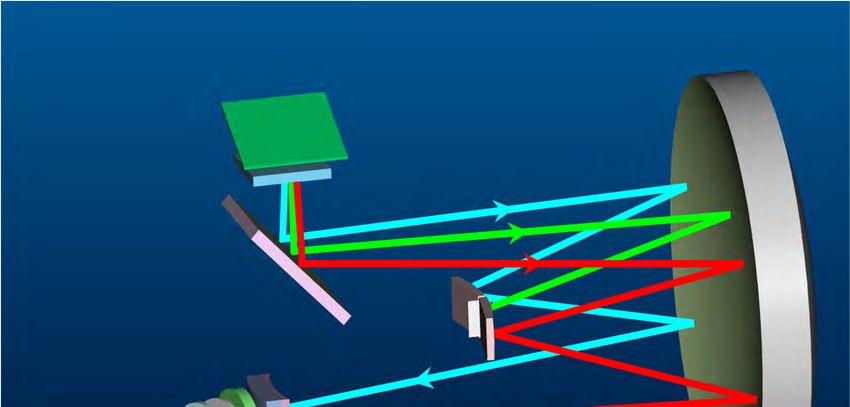
content
• What is Subaru telescope
• Why we use the prime focus?
    – merit vs. demerit
•   Suprime-Cam
•   FMOS (today’s main talk)
•   HSC
•   PFS (today’s sub-main talk)
•   Summary/Conclusion

                                  2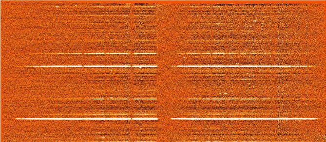
What is Subaru telescope
                                                              Suprime-Cam
                                                              FMOS
Primary Mirror                                                HSC
* Effective diameter: 8.2 m                                   PFS
* Thickness: 20 cm
* Active support: 261 actuators                IRCS
* Weight: 22.8 tons                            AO-188 w/LGS
* Material: ULE (ultra-low thermal expansion                           HDS
    glass)
* Mean Surface error: 12 nanometer
* Focal length: 15 m

Telescope Structure
* Mounting: altitude-azimuth (Alt-Az)
* Basic Optics: Ritchey-Chretian System
* Height: 22.2 m
* Maximum width: 27.2 m
* Weight: 555 tons
* Foci: Four
-Primary focus : F2.0 (with corrector lens)
-Cassegrain focus : F12.2                            MOIRCS
-Nasmyth focus (optical) : F12.6
                                                     FOCAS
-Nasmyth focus (infrared) : F13.6
                                                     COMICS
                                                                             3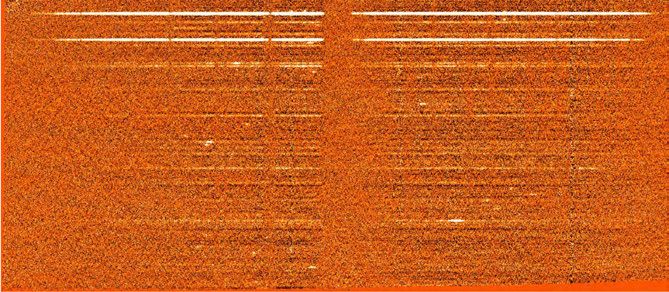
AO188                             Instruments
 - Subaru 188-elements Adaptive Optics system
 - diffraction-limited images in the near-infrared
COMICS
 - Cooled Mid-Infrared Camera and Spectrograph
 - imaging and spectroscopy from 8-25 microns
FMOS
 - Fibre Multi Object Spectrograph
 - Multi-object spectroscopy from 0.9-1.8 microns
FOCAS
 - Faint Object Camera And Spectrograph
 - optical imaging and longslit and multi-slit spectroscopy
HDS
 - High Dispersion Spectrograph
 - extremely high-resolution optical spectroscopy.
IRCS
 - Infrared Camera and Spectrograph
 - imaging from 0.9-5.5 microns
 - low-resolution and echelle spectroscopy
MOIRCS
 - Multi-Object Infrared Camera and Spectrograph
 - imaging and low-resolution spectroscopy
   from 0.9-2.5 microns, 4* 7 arcmin field of view.
Suprime-Cam
 - Subaru Prime Focus Camera
 - optical imaging, 30 arcmin field of view                   4
Prime focus

      3 secondary mirror
      3 prime focus units

                            5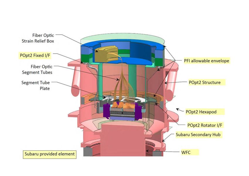
Merit vs. Demerit
              using the prime focus.
Merit                     Demerit
a small number of the     a severe limit of the
focal ratio               weight of the prime focus
                          instrument
a wide field of view,     a laborious work
suitable for the survey
observations.
                          a risk of giving a serious
                          damage to the main
                          mirror by falling items
                          from the instrument
                                                       6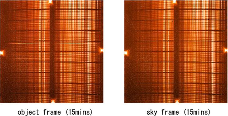
a laborious work,
a risk of giving a serious damage to the
               main mirror

                                           7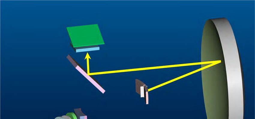
Serious Hardware Incident with the Subaru
Telescope (Suprime-Cam)
Interrupts Its Operation
While shutting down the observation
system at the end of the night shift
during the early morning of Saturday,
2nd, July 2011, the telescope operator
detected an error signal from the top
unit of the telescope.
              @ Subaru Web page

We need to consider risks of giving a
serious damage to the telescope and
instruments.

                                            8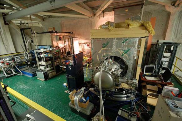
But, invaluable advantage
a small number of the focal ratio

a wide field of view, suitable for the survey
  observations.

                                                9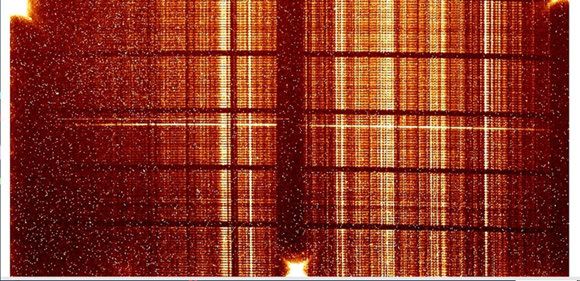
Suprime-Cam

• mosaic camera
    – ten - 2048 x 4096 CCDs
• 34' x 27' field of view
    – a pixel scale of 0.20''.
•   Pixel size 15 um
•   Gain 2.5-3.7 e-/ADU
•   Read noise 10 e-
•   Readout time 18 s

• hold 10 filters at a time
• Filter exchange time 300 s           Condition:
                                        S/N=5, 1 hour exp.
                                        good (0.5'') seeing
                                        a moderately dark sky
                                        (3 days from New Moon) 10
FMOS
Fibre Multi-Object Spectrograph
400 fibres on the prime focus
30’ diameter FoV
Each fibre (100 μm core)
~ 1”.2 on the sky.
wavelength coverage
0.9 – 1.8 um
2 spectrographs (200 spectra x 2)
operated at T= - 50 deg.
OH– airglow suppression
two spectral resolution modes :
Low R: R~500 (one exposure)
High R: R ~ 2200 (any ~ 0.2 μm)
FMOS consist of
Prime Focus unit
Echidna fibre positioner & fibre
cables and connector
Two cooled spectrographs
11FMOS instrument team
• Kyoto
– Instrument PI (Toshinori Maihara)
– Prime focus instrument bay
– One OHS spectrograph
– Observation software
• Oxford/RAL
– Spectrograph Design
– One OHS spectrograph
– Fibre back-illumination system
• Durham
– Fibre cables
– Top end fibre connector
– Slit assemblies
• AAO
– ECHIDNA fibre positioner & software
– Prime Focus Corrector
• Subaru
– New floor to house spectrographs
12• Mechanical/Optical structures of FMOS
– Prime focus unit for IR
– Fibre Positioner “Echidna” and Fibre connectors
– Two cooled spectrographs
• Results
• Conclusion
13Prime focus unit for IR
• Fibre positioner “Echidna”
• Wide-field corrector lens
• Instrument rotator with
Cable wrapper Cable
wrapper
• Optical adjustment FAM
mechanism Echidna
– Focus adjustment
mechanism (FAM)
AG/SH
– Corrector movement CMM
mechanism (CMM)
• Optical measurement
systems Corrector
lens
– Auto-guide system using
fibre bundles
– Shack Hartmann system
14Fiber positioner
Major fibre spectrograph
• FMOS is mounted the prime focus of
the telescope. And there is not
enough space in the prime focus unit.
• So, we developed new type of fibre
positioning. The patrol area of
each fibre is
– Spine type fibre positioner! φ7mm diameter.
The spacing between
neighboring spines is 7mm. 15Fibre positioner “Echidna”
Echidna
• Echidna
– Using tube piezo actuator
• Focal plane imager
– Two cameras:
• Spine camera
• Sky camera
Focal Plane imager
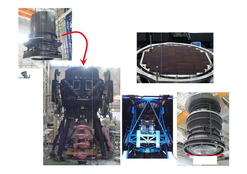
16Two Spectrographs
Size
~ 2.5m x 3m
x 2.5m
IRS1 IRS2
@Oxford Univ.
@Kyoto Univ.
& RAL
Optically
identical 17Two Spectrographs
Schmidt Grating 1.4m Main
Plate Mirror
Folding
Mirror
Camera
Fibre Slit
(200
fibers)
18Two Spectrographs
Mask Mirror 1.8
OH sky
m
0.9line
m
Camera
VPH Grating
Masked
Spectra Only used in Low R mode as “anti-disperser”.
Removed in High R mode. 19content
• Mechanical/Optical parts of FMOS
• Results
– How to observe?
– Previous commissioning/common use observations
– Fibre Auto guiding
– Echidna accuracy
– Spectrum image
– Performance
• Conclusion
20Planning Observation
1. Prepare a source list of science targets
1. Astrometry
2. Guide star
3. Coordinate calibration stars
2. Fibre allocation
1. Field centre
2. Position angle
3. Observation method (sky background subtraction)
1. Normal beam switching
2. Cross beam switching
3. Spectrographs
1. Low/high resolution mode
2. Exposure time
3. Calibration data
21Observation Procedure
1. Pointing the telescope & allocating fibres (include focusing)
1. Iterative process: Measure fibre positions and move spines.
(back-illumination light + spine camera)
Need 7 iteration (~15min.) > ~10um(0”.12)
2. Check field
Filed check using coordinate calibration star, offset-pointing and
rotation angle
2. Star auto guide ~20 min.
3. Start exposure
4. Re-configuration every 30 min. (~11min.)
On-source 3 hour exposure:
20min + (30 + 11)min x 6 = 266min
overhead = (266 – 180) ÷ 266 x 100 = 32.3 %
4. Data acquisition for flat-fielding and wavelength calibration
22Previous observations
• FMOS project started from 1999?
• Assembling started from 2005/May at Subaru
telescope site
• Engineering first light @ 2008/May
• Scientific engineering observation start form
2009/Dec
• Scientific observation start from 2010/May/28.
• Open-use observation start from 2010/May/29.
23Fibre Auto Guide
~ 2” A guide fibre bundle
= 0”.6 x 7 fibres
R =16-17 mag stars
worked for AG
400 science fibers
Populated within this
30’ diameter FoV
(~15cm)
14 fibre bundles
For Auto-Guide
24Fibre Auto Guide
Sky condition :
Median AG2-error ~ 0”.063
21/Apr/2010 night log
90%value ~ 0”.139 , 95%value ~ 0”.173 MASS ~ 0”.24±0”.12
@CFHT WX Tower seeing
Histogram
200 100%
Y-error [arcsec]
180 90%
160 80%
140 70%
120 60%
frequency
100 50%
80 40%
60 30%
40 20%
20 10%
0 0%
0.1
0.3
2
6
4
8
2
6
4
8
2
6
0.0
0.0
0.1
0.1
0.2
0.2
0.3
0.3
0.4
0.4
X-error [arcsec] guide error
25Echidna’s allocation error
Fibre allocation using catalogs
On-sky fibre position Telescope pointing
offset: 0”.5 ~ 1”.0 Telescope model ,,,
Measured offset between
the target and fibre
flux
5 x 5 tel. offset + exposure
→ 2D map of flux (spectrographs) Compare flux at each position
→ Centroid of star
26Positing accuracy of Echidna
Fine-tune telescope
model with “rastering”
Configure spines
based on the above
telescope model, and
acquire spectra of 400
fibers by “rastering”
telescope.
Position offset between
the targets and science
fibres
~ 0”.15 in rms
27Observation !
• Data sets @from Dec 2009
– SXDF field: 120 min exp time
– Lockman Hole: 90 min exp time
– And 5 other fields
• Data analysis:
– Estimate continuum flux by 5-ord Polynomial
smoothing
– Estimate emission line flux by Gaussian-fitting
– Only use data in J-band (λ=1.1-1.35) & H-band
(λ=1.4-1.7)
– Estimate noise by using 1d-spectra
28Detector image
Ramp sampling image at 15min exp . time
J-band H-band
Object – Sky Reduction
29Detector Image
IRS1 vs. IRS2
irs1_ELAIS_N1_SEabc_lrxpb.gif irs2_ELAIS_N1_SEabc_lrxpb.gif
30Reduction image
[OIII]
H 4959, 5007
H
[OIII] H
31Continuum flux sensitivity
A low resolution spectrum
CBS mode
1.5 hrs exp. Time
J = 20.1 mag., H = 19.7 mag
S/N = 4.9 @J-band,
4.5 @H-band
CBS mode
2hrs exp.time
J = 20.0 mag., H = 19.6 mag
S/N = 5.9 @J-band,
6.4 @H-band
32Continuum flux sensitivity
Lockman Hole field
CBS mode
1.5 hrs epx. time
Results:
J-band ~20.1 mag
H-band ~19.8mag
@ 1hrs, S/N=5
33Emission line sensitivity
An emission line
galaxy at z=1.5.
[OIII]5007 emission
is detected with
S/N~24, of which flux
is estimated to be
~5.4 x 10⁻¹⁶ erg cm-
2 s-1.
An AGN at z=1.35.
the narrow
[OIII]5007 emission
is detected with
S/N~5, of which flux
is estimated to be
~8 x 10-17 erg cm-
2 s-1.
34Emission line sensitivity
J-band: 1.0*10-16 [erg/cm2/s]
H-band: 0.9*10-16 [erg/cm2/s]
@1 hrs, S/N=5
35Conclusion of FMOS
• Open-use observation begin in May 2010.
• Allocate fibres (include focusing)
need 7 iteration (~15min.) within 10um(0”.12)
• Need re-configuration every 30 min.
On-source 3 hour exposure:
20min + (30 + 11)min x 6 = 266min
overhead = (266 – 180) ÷ 266 x 100 = 32.3 %
• Median AG2-error ~ 0”.063 @ MASS ~ 0”.24±0”.12
• Continuum flux @ 1hr, S/N=5
– J-band =20.1 mag & H-band = 19.8 mag
• Emission line sensitivity @1 hrs, S/N=5
– J-band = 1.0*10-16 [erg/cm2/s]
H-band = 0.9*10-16 [erg/cm2/s]
36SuMIRe Project
--- HSC and PFS ---
37History of HSC project
Year Milestone, Progress Budget, Organization People Org.
2002 Conceptual study of new Subaru R&D (Miyazaki+) 3 1
lens
2003~ CCD development, Grants-in-Aid(Miyazaki+) 6 1
Mechanics concept study
2005 ASIAA participation 10 2
2006~ CCD production, Lens, Grants-in-Aid (Karoji+) 33 4
Mechanics detail design
2007 Princeton participation ~40 5
2008 NAOJ Subaru HSC ~40 5
project established
2009 Design Review ~40 5
2010~ Stimulus Package ~40 5
(Murayama+)
2012 Lens and PFU completed ~40 5
Camera completed (?)
2012 ? First Light (planned) ~40 5
38HSC
Suprime-Cam HSC
CCD Make and model Hamamatsu S10892-01 Hamamatsu S10892-02
104 + AutoGuide4 +
Number of CCDs 10
AutoFocus 8
15 micron square (0.2 arc- 15 micron square
Pixel sec) (0.17 arc-sec)
Field of View34 arcmin x 27 arcmin 90 arcmin daiameter
Readout time 18 sec 20 sec
Number of filter 10 6
600 sec (900sec while
Filter exchange time 300 sec
commissioning)
39HSC
Φ82 cm 40PFS
Field of View 1.3 deg
Number of 2400
fibres
fibre Φ128μm(core diamter)
→1.13 arcsec on the
sky
Spectrograph 3-arm design, 4 sets
0.38-1.3μm
414-sets of Spectrograph
3-arm Coverage Resolution [λ/Δλ]
[A], Field
Blue 3800-6700 2200
Red 6500-10000 3500
IR 9700-13000 4500
42Prime focus instrument for PFS
Fiber Optic
Stra in Relief Box
POpt2 Fixed 1/F
PFI allowable envelope
Fiber Optic
Segment Tubes
Segment Tube
Plate
~ POpt2 Hexapod
P0pt2 Rotator 1/F
Subaru Secondary Hub
I Subaru provided element I
43Fibre Positioning system
Fibre stage
2400 Cobra 6 Auto guide
Fibre positioners cameras
Fibre arm
http://www.newscaletech.com/app_notes/Cobra-JPL-article.html
44Fibre positioner
Instrument FMOS PFS
Nickname Echidna COBRA
(针鼹) (眼镜蛇)
Type Tubular piezo actuator 2-axis picomotor
Driving method Tilt Rotation
2.4 mm radius
2.4 mm radius
Patrol area: 9.5mm dia.
control ○ ○
Twisted fibre ○ ×
Defocus × ○
45Measurement of the position and
Auto guide
Not enough space
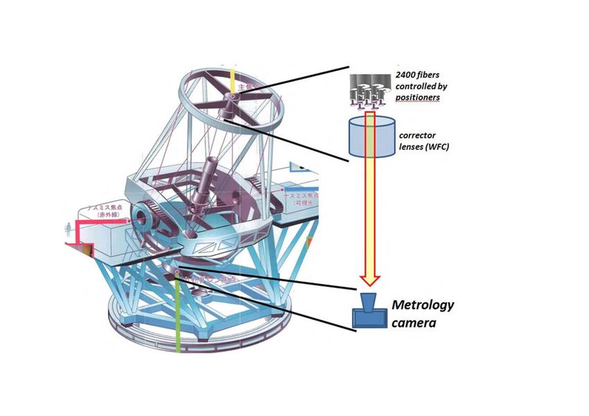
46Metrology Camera System
2400/ibers
controlled by
oositioners
corrector
lenses (WFC)
Metrology
camera
in-plane position of each fibre tip within an error of 5 μm
the centroid of all imaged fibre tips in less than 3s 47Auto guide
Instrument FMOS PFS
Type Fibre bundle Direct image (CCD camera)
~ 2”
merit Small space Direct image, known seeing
condition, focal plane distortion
48What to do in ASIAA?
• Configuration, preliminary design and
preliminary analysis will be by JPL
• Detailed design, analysis, fabrication,
handling fixtures and test will by ASIAA
almost ALL!
49Conclusion
• We start a realistic design for the prime
focus instrument.
50Question and answer
Question:
How do you suppress OH airglow lines?
Answer:
We use a mask mirror. The mask is made of a thin
(0.2mm in thickness) stainless-steel plate at the
positions of the strong OH-airglow lines, and
blackened to absorb the OH light.
More detail:
• http://subarutelescope.org/Introduction/instrument/OHS.html
• "The Fibre Multi-Object Spectrograph (FMOS) for Subaru
Telescope" Kimura, M., et al. 2010, PASJ, Vol. 62, 1135.
51Question and answer
Question:
Number density?
Answer:
The targets are randomly scattered over the field.
FMOS use 400 spine type fibres with 7mm pitch.
So, the number density of spines is 0.57 /
arcmin2., which is suitable for objects like
Extremely-Red Objects, Submm-bright sources,
Lyman Break Galaxies, and so on.
52You can also read