Inverness Airport - Airspace Change Proposal - Civil Aviation ...
←
→
Page content transcription
If your browser does not render page correctly, please read the page content below
Inverness Airport – Airspace Change
Proposal
Proposal to CAA SARG

Date: 9 Nov 17
Author:
Revision: Issue 1.2
Osprey Ref: 70550 061R

This document is of UK origin and has been prepared by Osprey
Consulting Services Limited (Osprey) and, subject to any existing rights of
third parties, Osprey is the owner of the copyright therein. The document
is furnished in confidence under existing laws, regulations and
agreements covering the release of data. This document contains
proprietary information of Osprey and the contents or any part thereof
shall not be copied or disclosed to any third party without Osprey’s prior
written consent.

© Osprey Consulting Services Limited 2017
1, The Bullpens, Manor Court, Herriard, Basingstoke. RG25 2PH.
Company Main 01420 520200 / enquiries@ospreycsl.co.uk
Registered in England and Wales under No: 6034579
Document Details
Reference                    Description

Document Title               Inverness Airport – Airspace Change Proposal

                             SARG Proposal

Document Ref                 70550 061R

Issue                        Issue 1.2

Date                         9 Nov 17

Client Name                  Highland and Island Airports Limited

Classification

Issue                        Amendment                                      Date

Issue 1.2

Approval Level               Authority                                      Name

Authors                      Osprey CSL

Internal Approval            Osprey CSL

Client 1 Approval            HIAL

Inverness Airport – Airspace Change Proposal | Document Details                    ii
70550 061R | Issue 1.2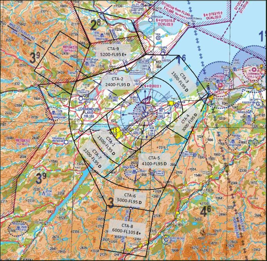
Executive Summary
Inverness Airport supports a vital and effective national and international flight network to both
the local community and wider Highlands area. Highlands and Islands Airports Limited (HIAL),
owner and operator of Inverness Airport, has identified the need for changes to the current
arrangements and procedures in the immediate airspace surrounding Inverness Airport. These
changes are being driven by advances in Air Traffic Management (ATM), airliner navigation and
routing procedures plus General Aviation (GA) navigation. The purpose of the changes being
proposed is to ensure that environmental and economic benefits are achieved through efficient
use of surrounding airspace and procedures, providing protection on critical stages of flight
following departure and prior to arrival for Instrument Flight Rules (IFR) commercial air
transport flights and arrival for Visual Flight Rules (VFR) flights.

HIAL proposes to introduce a system of aRea NAVigation (RNAV) Standard Instrument
Departures (SIDs) and RNAV1 Transitions (connecting a Standard Arrival (STAR) to the
destination Initial Approach Fix (IAF). These new routes will take advantage of improved
navigational capability which will allow enhanced systemisation and enable more efficient use
of the airspace. The efficient use of airspace will also enable the environmental impact of
aircraft to be lowered by reducing average CO2 emissions per flight.

If the proposal is approved by the UK Civil Aviation Authority (CAA), implementation of these
changes will occur at an appropriate opportunity after 1st March 2018.

The Issue
In 2016, Inverness Airport handled over 830,000 terminal passengers (a 24% year-on-year rise
in passenger numbers from 2015), thanks in part to continued interest in European routes to
Geneva, Zurich and Dublin and increased traffic to UK airports such as Manchester. Greater
connectivity to hub airports including London Heathrow and Schiphol, Amsterdam contributed
to its success.

The Airport is situated low ground at the north end of The Great Glen, with significant high
ground to the northwest and southeast. Inverness has, in common with Scotland, an oceanic
climate1. Its sheltered location makes it one of the driest areas in Scotland. In terms of snowfall
Inverness sees around 18.3 days of falling snow per year. When atmospheric low pressure
dominates the environment the Airport can suffer extended periods of dense, low fog (haar),
trapped and cooled between the high ground, which typically affects Airport movements but
transit air traffic above 500 feet (ft) above ground level (agl) can remain unaffected and

1 A climate typical of west coasts in higher middle latitudes of continents, and generally features cool summers
(relative to their latitude) and cool but not cold winters, with a relatively narrow annual temperature range and few
extremes of temperature.

Inverness Airport – Airspace Change Proposal | Executive Summary                                                        iii
70550 061R | Issue 1.2
continue to operate to Visual Meteorological Conditions (VMC). The Airport also lies to the
south and east of major military aviation restricted areas; the Highlands Restricted Area used
for low-flying training and the Tain Weapons Area used predominantly for air-groundweapons
release. To the east of the Airport is RAF Lossiemouth, a Main Operating Base (MOB) for the
Eurofighter fast jet aircraft. These factors of climate, terrain and military aviation activity mixed
with airliner and GA movements provide a challenging air traffic environment for the Airport’s
ir Traffic Control (ATC).

HIAL identified some time ago the need for changes to the current arrangements and
procedures in the immediate airspace surrounding the Airport. Inverness Air Traffic Control
(ATC) currently operates in a Class G airspace environment where frequent radio
communication intervention is required to enable Instrument Flight Rules (IFR) traffic,
predominantly commercial airliners, to arrive and depart the Airport. The purpose of the
change is to ensure future efficient use of surrounding airspace and that current effectiveness is
preserved for all aircraft.

Updating the airspace design gives HIAL the opportunity to improve airspace efficiency
(through proactive, rather than reactive, ATM), and better match the airspace and procedures
therein to the improved performance capabilities of more modern aircraft. The net effect of
these proposals would be to enhance the overall efficiency of airspace management for
Inverness Airport Air Traffic Control (ATC), and to achieve connectivity to the wider air route
network. This document outlines the proposals from HIAL for the enhancement of Inverness
Airport’s procedures and the establishment of appropriate airspace, to benefit both operators
and the local community.

Inverness Airport – Airspace Change Proposal | Executive Summary                                   iv
70550 061R | Issue 1.2
Figure 1 - Geographic extent of the Inverness Control Zone (CTR) and Control Areas (CTA)
UK Civil Aviation Authority (CAA) / NATS Digital Data. VFR Chart Scotland, 500,000, June 2013
Consultation
HIAL undertook two periods of consultation;
The first consultation took place from 29th September 2014 to 19th April 2015 (a period
of 29 weeks) and requested feedback on the airspace design, the initial Consultation
Document is Enclosure 1, the feedback was analysed and the Feedback Report is
included as Enclosure 2;
The second consultation (Addendum, Second Consultation Document is Enclosure 3),
took place from 15th August 2016 to 6th November 2016 (a period of 12 weeks) and
requested further feedback Addendum, Second Feedback Report is included as
Enclosure 4.
Inverness Airport – Airspace Change Proposal | Executive Summary v
70550 061R | Issue 1.2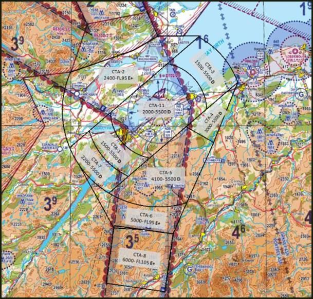
Local aviation stakeholders were directly consulted through the General Aviation (GA) focus
group and email messages (providing an attached consultation document or details of the
consultation webpage) sent directly to the National Air Traffic Management Advisory
Committee (NATMAC), airport operators, Regional, Highland Unitary Community Councils and
local Members of the UK and Scottish Parliaments. A number of National heritage and
environmental organisations were also contacted. In addition, general public consultation was
undertaken by publication of the consultation material on the HIAL website. The consultation,
which we believe was proportionate, solicited comment from a wide, but dispersed community,
on the proposal and helped to refine this accordingly prior to any implementation.
Proposed Solution
In developing the plans to resolve the issues described above, HIAL has considered a variety of
options in the two phases of Consultation to determine how best to meet the needs of Inverness
Airport, as well as other aviation and non-aviation stakeholders. The initial consultation was
based on the airspace design in Figure 1.
The major changes incorporated in the new proposed design, Figure 2 above, respond to
comment and concern, the majority from the local GA community to the initial design (Figure 1).
The major changes to the airspace design include:
Reduction in the lateral extent of the Class D airspace;
Reduction in the number of Class D Control Areas (CTAs) from seven to six;
Reduction in the vertical limit of the Class D Control Zone (CTR), previously from surface
to Flight Level (FL)95, now surface to 2,000 ft above mean sea level (amsl);
Reduction in the common ceiling altitude of the Class D CTAs from FL95 to 5,500 ft amsl;
Class E + Transponder Mandatory Zone (TMZ) CTAs have replaced some previous Class
D CTAs, the total now four, to be contiguous with the Class E + TMZ airways above the
Airport forming part of the UK en-route airways structure.
This document outlines the proposal from HIAL to maintain the effectiveness and efficiency of
the airspace surrounding Inverness Airport based upon radar surveillance in and around the
proposed Controlled Airspace (CAS).
The revised extent of the airspace design for this proposal is shown in Figure 2 below.
Inverness Airport – Airspace Change Proposal | Executive Summary vi
70550 061R | Issue 1.2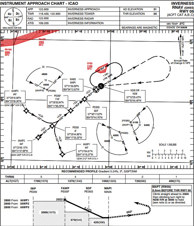
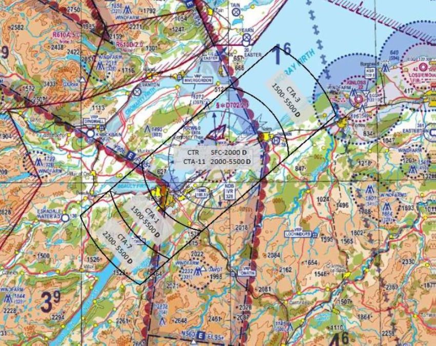
Figure 2 - Geographic extent of the Inverness Control Zone (CTR) and Control Areas (CTA)
           UK Civil Aviation Authority (CAA) / NATS Digital Data. VFR Chart Scotland, 500,000, June 2013

Inverness Airport – Airspace Change Proposal | Executive Summary                                           vii
70550 061R | Issue 1.2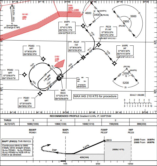
Table of Contents
1                Glossary ..................................................................................................................................... 1

2                Introduction ............................................................................................................................. 5

2.1              General ................................................................................................................................................................. 5
2.2              Justification ........................................................................................................................................................ 5
2.3              Background ........................................................................................................................................................ 7
2.4              Addressing Concerns..................................................................................................................................... 7
2.5              Environmental Issues ................................................................................................................................... 8
2.6              Safety..................................................................................................................................................................... 9

3                CAS Design Requirements ..................................................................................................10

3.1              Overview ...........................................................................................................................................................10
3.2              Aims .....................................................................................................................................................................10
3.3              Supporting Infrastructure ........................................................................................................................11
3.4              Procedures Justification.............................................................................................................................12

4                Other Design Requirements ..............................................................................................18

4.1              Environmental Considerations ..............................................................................................................18
4.2              User Impact......................................................................................................................................................19

5                Proposed Airspace Design..................................................................................................22

5.1              Introduction.....................................................................................................................................................22
5.2              VFR Flights and Visual Reference Points (VRP) .............................................................................28

6                IAIP Amendment ...................................................................................................................31

6.1              ENR 1.4...............................................................................................................................................................31
6.2              ENR 2.1...............................................................................................................................................................31
6.3              ENR 3.1, 3.2, 3.3 .............................................................................................................................................31
6.4              ENR 4.4...............................................................................................................................................................31
6.5              ENR 6 Charts ...................................................................................................................................................32
6.6              VFR CHARTS ....................................................................................................................................................32
6.7              AD-2-EGPE-8-w-z..........................................................................................................................................32
6.8              AD 2.EGPE-1 ....................................................................................................................................................32

References ..................................................................................................................................................33

A1               Airspace Coordinates ...........................................................................................................34

Inverness Airport – Airspace Change Proposal | Table of Contents                                                                                                                         viii
70550 061R | Issue 1.2
A1.1                CTR and CTA-11 .............................................................................................................................................34
A1.2                CTAs .....................................................................................................................................................................35
A1.3                Inverness Airport Data ...............................................................................................................................38

A2                  Airspace Description Requirement .................................................................................39

A3                  Supporting Infrastructure and Resources ....................................................................41

A4                  Operational Impact ..............................................................................................................43

A5                  Airspace and Infrastructure Requirements..................................................................44

Table of Figures
Figure 1 - Geographic extent of the Inverness Control Zone (CTR) and Control Areas (CTA) UK
Civil Aviation Authority (CAA) / NATS Digital Data. VFR Chart Scotland, 500,000, June 2013 ........v
Figure 2 - Geographic extent of the Inverness Control Zone (CTR) and Control Areas (CTA) UK
Civil Aviation Authority (CAA) / NATS Digital Data. VFR Chart Scotland, 500,000, June 2013 ..... vii
Figure 3 – Inverness Runway 05 SIDs, CTR and CTAs .......................................................................................13
Figure 4 – Inverness Runway 23 SIDs, CTR and CTAs .......................................................................................14
Figure 5 – Inverness Runway 05 Transitions, CTR and CTAs ........................................................................15
Figure 6 – Inverness Runway 23 Transitions, CTR and CTAs ........................................................................16
Figure 7 – Draft Inverness Runway 05 RNAV (GNSS) Final Approach ......................................................17
Figure 8 – Draft Inverness Runway 23 RNAV (GNSS) Final Approach ......................................................17
Figure 9 - Proposed Inverness Airport Class D CTR and Centre Line CTAs Only (ceiling altitude
of 5,500 ft shown) ................................................................................................................................................................22
Figure 10 - Proposed Inverness Airport Class D (Ceiling 5,500ft) and E+TMZ CTAs .........................23
Figure 11 - Proposed Inverness Airport Class E+TMZ CTAs Only ................................................................24
Figure 12 - Proposed VFR Routes ................................................................................................................................28

Table of Tables
Table 1 - Glossary ................................................................................................................................................................... 4
Table 2 – Inverness Airport CAS Areas......................................................................................................................27
Table 22 - Table of References ......................................................................................................................................33
Table 3 – CTR Coordinates ..............................................................................................................................................34
Table 4 – CTA-11 Coordinates .......................................................................................................................................34
Table 5 – CTA-1 Coordinates ..........................................................................................................................................35
Table 6 – CTA-2 Coordinates ..........................................................................................................................................35
Table 7 – CTA-3 Coordinates ..........................................................................................................................................36
Table 8 – CTA-4 Coordinates ..........................................................................................................................................36
Table 9 – CTA-5 Coordinates ..........................................................................................................................................36

Inverness Airport – Airspace Change Proposal | Table of Contents                                                                                                                             ix
70550 061R | Issue 1.2
Table 10 – CTA-6 Coordinates .......................................................................................................................................37
Table 11 – CTA-7 Coordinates .......................................................................................................................................37
Table 12 – CTA-8 Coordinates .......................................................................................................................................37
Table 13 – CTA-10 Coordinates ....................................................................................................................................38
Table 14 – CTA-10 Coordinates ....................................................................................................................................38
Table 15 – airspace Requirements ..............................................................................................................................40
Table 16 – airspace Requirements ..............................................................................................................................42
Table 17 – airspace Requirements ..............................................................................................................................43
Table 18 – Airspace Requirements (A11) ................................................................................................................46
Table 19 – Airspace Requirements (A12) ................................................................................................................46
Table 20 – Airspace Requirements (A13) ................................................................................................................48
Table 21 – Airspace Requirements (A14) ................................................................................................................49

Table of Enclosures
Enclosure 1 – Initial, First Consultation Document
Enclosure 2 – Initial Feedback Report
Enclosure 3 – Addendum, Second Consultation Document
Enclosure 4 – Second Feedback Report
Enclosure 5 – ERCD Reports
       5A - Noise
       5B - Emissions
       5C – Emissions v2
       5D –Emissions Supplemental
Enclosure 6 – Safety Assessment
       6A – Safety Case Part 1
       6B – Safety Case Part 2
       6C – Safety Case Parts 3 and 4
Enclosure 7 – SID05 v 1
Enclosure 8 – SID23 v1
Enclosure 9 – Transition05 v 4
Enclosure 10 – Transition23 v 5
Enclosure 11 – GNSS App05
Enclosure 12 – GNSS App23
Enclosure 13 – RAF Lossiemouth/Tain Range/Inverness ATC LoA
Enclosure 14 – Inverness ATC Example Watch Roster
Enclosure 15 – HGC Letters
Enclosure 16 – CGC Letters
Enclosure 17 – PDG/Inverness ATC LoA
Enclosure 18 – Inverness ATC/NATS (Prestwick ACC) LoA
Enclosure 19 – Inverness ATC CAS Training Plan
Enclosure 20 – Inverness ATC CAS Simulator Programme

Inverness Airport – Airspace Change Proposal | Table of Contents                                                                                                    x
70550 061R | Issue 1.2
Enclosure 21 – Procedures Flight Validation Plan Enclosure 22 – Inverness Airport Air Traffic Forecast Enclosure 23 – Inverness ATC Radio Coverage Enclosure 24 – Inverness ATC Communications Contingency Plan Enclosure 25 – Inverness PSR Coverage Enclosure 26 – Draft AD 2.EGPE-1 amendment Inverness Airport – Airspace Change Proposal | Table of Contents xi 70550 061R | Issue 1.2
1           Glossary

                Table of abbreviations and acronyms.

            Acronym         Meaning

            ACP             Airspace Change Proposal

            amsl            Above mean sea level

            APCH            Approach

            ARP             Aerodrome Reference Point

            ATC             Air Traffic Control

            ATM             Air Traffic Management

            ATS             Air Traffic Service

            CAA             Civil Aviation Authority

            CAP             Civil Aviation Publication

            CAS             Controlled Airspace

            CAT             Commercial Air Traffic

            CCD             Continuous Climb Departure

            CDA             Continuous Descent Approach

            CTA             Control Area (Class D UK Airspace)

            CTR             Control Zone

            DME             Distance Measuring Equipment

Inverness Airport – Airspace Change Proposal | Glossary          1
70550 061R | Issue 1.2
Acronym Meaning
DS Deconfliction Service
EASA European Aviation Safety Agency
FIS Flight Information Service
FPL Flight Plan
ft Feet
GA General Aviation
GAT General Air Traffic
GNSS Global Navigation Satellite Service
HIAL Highlands and Islands Airports Ltd
HRA Highlands Restricted Area
IAIP Integrated Aeronautical Information Package
IAP Instrument Approach Procedure
IFP Instrument Flight Procedure
IFR Instrument Flight Rules
IGAFG Inverness General Aviation Focus Group
IMC Instrument Meteorological Conditions
LAA Light Aircraft Association
LoA Letter of Agreement
MoD Ministry of Defence
NATMAC National Air Traffic Management Advisory Committee
Inverness Airport – Airspace Change Proposal | Glossary 2
70550 061R | Issue 1.2Acronym Meaning
NATS The National Air Traffic Service Provider
NDB Non Directional Beacon
NM Nautical Miles
NPA Noticed of Proposed Amendment (EASA)
PANS-OPS Procedures for Air Navigation Services - Operations
PBN Performance Based Navigation
RAF Royal Air Force
RNAV Area Navigation
RNP Required Navigation Performance
RNP AR RNP Authorization Required
RNP RP RNP Reporting Point
Rwy Runway
SARG CAA Safety and Airspace Regulation Group
SBAS Satellite Based Augmentation System
SERA Standard European Rules of the Air
SID Standard Instrument Departure
SSR Secondary Surveillance Radar
SVFR Special Visual Flight Rules
TMZ Transponder (SSR) Mandatory Zone
VFR Visual Flight Rules
Inverness Airport – Airspace Change Proposal | Glossary 3
70550 061R | Issue 1.2Acronym Meaning
VMC Visual Meteorological Conditions
VOR VHF Omni Directional Radio Range; a type of short-range radio navigation
system for aircraft
VRP Visual Reference Point
Table 1 - Glossary
Inverness Airport – Airspace Change Proposal | Glossary 4
70550 061R | Issue 1.22 Introduction
HIAL, owner and operator of Inverness Airport, has identified the need for
changes to the current arrangements and procedures in the immediate airspace
surrounding Inverness Airport.
2.1 General
Highlands and Islands Airports Limited (HIAL) is a public corporation, wholly owned by the
Scottish Ministers. The Company is responsible for the operation and management of 11
airports (Barra, Benbecula, Campbeltown, Inverness, Islay, Kirkwall, Stornoway, Sumburgh,
Tiree and Wick) in the Highlands and Islands, and Dundee.
HIAL’s Board of Directors is accountable to the Scottish Ministers.
2.2 Justification
HIAL identified some time ago the need for changes to the current arrangements and
procedures in the immediate airspace surrounding the Airport. Inverness Air Traffic Control
(ATC) currently operates in a Class G airspace environment where frequent radio
communication intervention is required to enable Instrument Flight Rules (IFR) traffic,
predominantly commercial airliners, to arrive and depart the Airport. The purpose of the
change is to ensure future efficient use of surrounding airspace and that current effectiveness is
preserved for all aircraft.
HIAL seeks to upgrade arrival and departure routes to take advantage of the improved
navigational capabilities of RNAV1 and improve the efficiency and capacity of the airspace
around Inverness Airport by utilising CAS. The changes will:
Minimise the impact to people on the ground and minimise the number of
people impacted by aircraft noise from overflights below 4,000ft;
make improvements to departure routes utilising RNAV1 capabilities;
make efficiency improvements to the arrival routes based on RNAV1 arrival
transitions; and
position IFR passenger carrying airliners more accurately allowing arrival
and departures routes to be flown more accurately (hence impacting fewer
people).
Inverness Airport – Airspace Change Proposal | Introduction 5
70550 061R | Issue 1.2HIAL’s aim is to meet these requirements, maximising benefits to Inverness, The Highlands and
Scotland whilst minimising any negative impacts. HIAL is seeking to minimise the population
impacted under the routes by rationalising the current ‘vectored’ or ‘procedural’ approach and
departures made in the existing Class G airspace environment. CAS and improved track keeping
means that there will be less dispersal of aircraft either side of route nominal centrelines over
sparsely populated areas. This would mean a reduction in the overall area regularly overflown
(but a corresponding increase in the concentration of over-flights in some areas, predominantly
close to the Airport and its extended runway centrelines).
Updating the airspace design gives HIAL the opportunity to improve efficiency, and better
match it to the improved performance capabilities of more modern aircraft. The net effect of
these proposals would be to enhance the overall efficiency of airspace management for
Inverness Airport, and to achieve connectivity to the wider air route network..
Introduction of RNAV1 SIDs and arrival transitions at Inverness Airport would improve
systemisation and upgrade the navigation capability in accordance with the CAA Future
Airspace Strategy (FAS) recommendations.
2.2.1 Enclosures
Enclosed with this proposal are the following documents:
1. Initial, First Consultation Document
2. Initial Feedback Report
3. Addendum, Second Consultation Document
4. Second Feedback Report
5. ERCD Reports
A. Noise
B. Emissions
C. Emissions v2
D. Emissions Supplemental
6. Safety Assessment
A. Safety Case Part 1
B. Safety Case Part 2
C. Safety Case Parts 3 and 4
7. SID05 v 1
8. SID23 v1
9. Transition05 v 4
10. Transition23 v 5
11. GNSS App05
12. GNSS App23
13. RAF Lossiemouth/Tain Range/Inverness ATC LoA
14. Inverness ATC Example Watch Roster
15. HGC Letters
16. CGC Letters
Inverness Airport – Airspace Change Proposal | Introduction 6
70550 061R | Issue 1.217. PDG/Inverness ATC LoA
18. Inverness ATC/NATS (Prestwick ACC) LoA
19. Inverness ATC CAS Training Plan
20. Inverness ATC CAS Simulator Programme
21. Procedures Flight Validation Plan
22. Inverness Airport Air Traffic Forecast
23. Inverness ATC Radio Coverage
24. Inverness ATC Communications Contingency Plan
25. Inverness PSR Coverage
26. Draft AD 2.EGPE-1 amendment
2.3 Background
The initial Consultation on this proposal was carried out by HIAL between 29th September 2014
and 19th April 2015 in accordance with the requirements of CAA Civil Aviation Publication (CAP
725). In that Consultation a total of 116 responses were received; 5 consultees supported the
proposal; 99 consultees objected to the proposal; and 12 consultees provided a neutral
response, whereby the consultee did not object or provided no comments on the proposal.
The Consultation produced a significant opposition from the local GA community supported by
the GA Alliance and the Light Aircraft Association (LAA) Highland and Islands Strut. The foci of
concern are as follows:
The extent of the suggested CAS is disproportionate to density of commercial
activity at Inverness Airport;
Access arrangements to the CAS;
The base level of some Control Areas within the overall CAS design; and
The future impact of the Standardised European Rules of the Air (SERA),
specifically the changes to visual flight requirements within CAS.
An extensive design iteration took into account comments received during the initial
consultation. Significant changes have been made to the design (in geographic extent, volume
and type) of the proposal for Inverness Airport CAS. HIAL believes the revision has increased
the flexibility for VFR operations, both for GA and the Ministry of Defence (MoD), within and
around the designed CAS and increased the integrity of information readily available to VFR
aircraft commanders in ‘two-way’, air-ground, radio contact with Inverness Airport ATC.
2.4 Addressing Concerns
In some areas, it has not been possible to reduce substantially the lateral dimensions of
proposed CTAs, but it has been possible to change the classification and vertical dimensions,
predominantly aimed at increasing VFR access, with transponder carriage, to the CAS.
Inverness Airport – Airspace Change Proposal | Introduction 7
70550 061R | Issue 1.2A detailed review of the initial concepts, held in conjunction with the RAF Lossiemouth
Operations Wing, the Inverness General Aviation Focus Group (IGAFG) and Tain Range Control
resulted in a further reduction in the overall volume of CAS required. Primarily, this has been
achieved by removing a CTA from above EG R610D. Extensive use of Class E + TMZ airspace for
CTAs 2, 6, 8 and 10 has significantly increased flexibility for VFR operations above 5,500 ft
within the designed Inverness Airport CAS core (CTA 10), above 2,400 ft in CTA 2, above 5,000
ft in CTA 6 and above 6,000 ft in CTA 8 . The inclusion of the Class D CTA-11 above a ‘capped’
Control Zone (CTR) of ceiling 2,000 ft has increased VFR flexibility in poor weather conditions at
the Airport. Furthermore, the change to Class E + TMZ airspace in CTAs-2 and 6 has mitigated
the concerns regarding VFR, Class G ‘head room’ between the base of these CTAs and the
underlying terrain and VFR operations from GA aerodromes near or underneath these CTAs.
Comment has also been received stating that a local Community Council was not consulted. It is
acknowledged that a direct email was not sent to some Council Secretaries at the time of the
second consultation. This has been addressed and emails have been sent (4th August 2017) to
all Moray Community Council Secretaries reminding the Councils of the recent consultation and
requesting a response by 18th September 2017 (providing a 6 week window for responses).
2.4.1 Airspace Adjustment following the First Consultation
The major changes incorporated in the new proposed design reflect comment and concern, the
majority from the local GA community to the initial design The major changes to the airspace
design include:
Reduction in the lateral extent of the Class D airspace;
Reduction in the number of Class D Control Areas (CTAs) from seven to six;
Reduction in the vertical limit of the Class D Control Zone (CTR), previously from
surface to Flight Level (FL)95, now surface to 2,000 ft above mean sea level
(amsl);
Reduction in the common ceiling altitude of the Class D CTAs from FL95 to 5,500
ft amsl;
Class E + Transponder Mandatory Zone (TMZ) CTAs have replaced some
previous Class D CTAs, the total now four, to be contiguous with the Class E +
TMZ airways above the Airport forming part of the UK en-route airways
structure.
2.5 Environmental Issues
Currently the predominant environmental issue is the impact of aircraft noise on local
populations due to overflight below 4,000ft that occurs near the Airport and close to the runway
centrelines. As outlined in the Consultation Documents (Enclosures 1 and 3) Section 6, the
highest priority environmental objective for this change is to minimise cumulative track miles
flown by airliners into and out of Inverness Airport. This is achieved through uninterrupted
Inverness Airport – Airspace Change Proposal | Introduction 8
70550 061R | Issue 1.2procedures, using continuous descent and climb operations. Implementing these objectives would relieve the local populations, overflown below 4,000ft and away from the runway centrelines, of excessive noise intrusion from airliners. Other environmental objectives are to minimise the population overflown by aircraft between 4,000 and 7,000ft. Detailed analysis of the environmental impact of the proposed new routes is given in the Environmental Reports Enclosures 5A-D. This includes analysis of the current ‘vectored’ environment against the proposed routes for the impact on CO2 emissions, fuel burn, track mileages, noise impact, tranquillity and local air quality. 2.6 Safety There are no specific safety issues in the current operation. Ensuring the safety of proposed changes is a priority for Inverness Airport. Safety Assessments are enclosed (Enclosures 6A-C). All proposed procedures have been designed in accordance with ICAO Procedures for Air Navigation Services (Operations) PANS-OPS RNAV procedure design criteria (Reference 1). Inverness Airport – Airspace Change Proposal | Introduction 9 70550 061R | Issue 1.2
3 CAS Design Requirements
This Section reviews the aviation-related requirements for the CAS design.
3.1 Overview
The design of CAS is a careful balance between the competing needs of all of the various
airspace users, but in particular the GA (Sports & Recreation) stakeholders. Any design must
take into account the environmental impact of aircraft and ensure the preservation of safe
operations. Following comments received during the first consultation period, extensive
changes have been made to the proposed new airspace surrounding Inverness Airport. This
Section provides full details of the current proposed airspace and procedures.
3.2 Aims
The overall aim, as a consequence of the objectives at Section 2.5, of the Inverness Airport
Airspace Change Proposal (ACP) is to enhance effectiveness and improve the efficiency of
Inverness Airport’s operations whilst minimising adverse effects to General Air Traffic (GAT)
and the environment. The proposed designs will achieve this through:
The introduction of optimal arrival and departure routes, improving
efficiency whilst reducing the noise impact of arriving and departing
airliners;
The introduction of Continuous Descent Approaches (CDAs) and Continuous
Climb Departures (CCDs) to reduce environmental impact. Reductions in
fuel emissions will be achieved through the establishment of Instrument
Flight Procedures (IFPs), which incorporate the use of the new technical
navigational developments of Satellite-Based Augmentation Systems (SBAS);
The establishment of Instrument Approach Procedures (IAPs )(Global
Navigation Satellite System (GNSS) final approaches) which incorporate the
use of new technical navigational developments through SBAS;
The design of airspace to adequately contain these IFPs, provide national
route connectivity and provide protection for all aircraft operating near
Inverness Airport whilst improving flexibility away from the Airport’s
immediate vicinity.
Additionally, there is an undeniable airline perception that CAS provides a greater degree of
protection to its operations than Class G airspace and business plans are influenced by this
Inverness Airport – Airspace Change Proposal | CAS Design Requirements 10
70550 061R | Issue 1.2perception. In HIAL’s specific experience, as recently as winter 2016/17 the airline Flybe suspended its flights between Dundee and Amsterdam. The airline stated that due to topography and high levels of light aircraft activity (in Class G airspace), it became clear that enhanced radar coverage is required to accommodate large passenger aircraft. Dundee is unable to provide this enhanced radar coverage, resulting in the airline suspending its operation of larger aircraft. Inverness lies within similar topography with high levels of fast jet (from RAF Lossiemouth) and light aircraft activity in the surrounding airspace, albeit with the provision of UK Flight Information Services (FIS) from Inverness ATC. However, this means that Inverness ATC is bound (contractually) to provide a Deconfliction Service (DS under UK FIS) to IFR airliners operating, to and from Inverness Airport, in the Class G airspace surrounding the Airport. This is a reactive and high workload service, which frequently results in an inefficient routing for airliners. The European Aviation Safety Agency (EASA) consultation for Air Traffic Services (ATS- 20161114) implied that aerodrome radar surveillance based ATS provision should only be made in CAS. HIAL supports this assertion, supplementing the Inverness Airport ATS provision with CAS protection for Commercial Air Transport operations (CAT) into and out of the Airport Class G airspace. 3.3 Supporting Infrastructure RNAV1 navigation is GPS derived rather than reliant on ground based infrastructure. RNAV1 requires that any proposed route shall have excellent, reversionary / secondary Distance Measuring Equipment (DME) coverage. Inverness has several of these facilities within close range; thus allowing for contingency should any ground based facility fail. A DME (coding – ILN/X) is located at Inverness Airport, with operational coverage of 40 NM. The Airport ATC system would initially recognise a VOR or DME failure via its monitoring equipment. Inverness APP/Radar would be informed and this failure would then be subject to promulgation via NOTAM. Information relating to a local failure would be broadcast via the Airport ATIS. The Highlands area is within good satellite coverage for Global Navigation purposes. Any RNAV1 departure would be strictly monitored by Inverness radar using both primary and secondary radar as an additional safeguard. Standard radar separation would apply at all times, 1000 ft vertically and/or 3 NM laterally, regardless of whether the departure was conducted via RNAV1 or radar vectors. The RNAV1 SIDs and Transitions will only be available to aircraft which are equipped and operated in accordance with the requirements of JAA TGL-10 or equivalent, and approved by their State of Registry for RNAV1 (formally P-RNAV) operations. This requires aircraft to be GNSS equipped or to have DME/DME and INS/IRU with an automatic runway update capability. Additionally flight crews have to complete appropriate RNAV1 training and be approved by the appropriate state authorities to conduct RNAV1 operations. The majority of aircraft currently using Inverness Airport are anticipated to be able to utilise the RNAV1 SIDs and Transitions if they come into operation, and the number of users is expected to rise over the coming years. Inverness Airport – Airspace Change Proposal | CAS Design Requirements 11 70550 061R | Issue 1.2
RNAV SIDs and Transitions will be differentiated from conventional procedures by the
designator and will be published on separate charts in the UK Integrated Aeronautical
Information Package (IAIP). Crews of approved operators requesting a RNAV1 procedure will
request this when obtaining their clearance from ATC. Aircraft without an approval from ATC to
fly the procedure will be issued with the current conventional radar clearance plus vectors
clearances even where suitably equipped in accordance with JAA TGL-10. Conventional radar
vector procedures will therefore remain in force, and these will be used for those
aircraft/airlines that are not equipped to fly RNAV1 procedures, or for when an ATC clearance
cannot be issued for the use of the RNAV1 procedures.

3.4         Procedures Justification
The Inverness Airport VHF Omnidirectional Radio (VOR) (coding - INS) is due to be withdrawn
in 2019 under the National Air Traffic Services (NATS) VOR Rationalisation and Replacement
Programme. This will result in the loss of the primary Inverness Airport arrival and departure
aid. It is therefore intended to introduce Area Navigation (RNAV) GNSS IAPs, which replicate the
current final approach tracks, coincident with the implementation of the airspace change. IFPs,
founded on the technological advancements of RNAV and Required Navigation Performance
(RNP) through Performance Based Navigation (PBN), are needed to link to these IAPs, allowing
transition from ground-based navigation to satellite-based navigation.

3.4.1       SIDs

Overview diagrams of the proposed SIDs are given in Figures 3 and 4 below (detailed designs
Enclosures 7 and 8). It is intended to introduce a set of three SIDs for each runway. These routes
accommodate direct departures that account of underlying terrain and urban areas on each of
the three exit air routes; one to Glasgow and one each to the northern and Western Isles. The
departure routes reduce track miles flown and consequently reduce fuel emissions. In addition,
shorter routes will decrease the inherent noise footprint for the benefit of the Airport’s wider
community.

Inverness Airport – Airspace Change Proposal | CAS Design Requirements                          12
70550 061R | Issue 1.2
Figure 3 – Inverness Runway 05 SIDs, CTR and CTAs

The SIDs incorporate CCDs that reduce the environmental impact by minimising the fuel burn
when climbing into the en-route airways structure. Additional routings were also considered,
but HIAL studied departure statistics and discarded probable low frequency departure routes
that would add complexity, and potentially not reduce cumulative track miles, in order to
minimise the impact on other airspace users. The proposed SIDs are unchanged from those
presented in the consultation of 2014/15.

Inverness Airport – Airspace Change Proposal | CAS Design Requirements                         13
70550 061R | Issue 1.2
Figure 4 – Inverness Runway 23 SIDs, CTR and CTAs

3.4.2       Transitions

Overview diagrams of the proposed Transitions are given in Figures 5 and 6 below (detailed
designs Enclosures 9 and 10). It is intended to introduce a set of three Transitions for each
runway. These routes accommodate direct arrivals. The Transitions take into account
underlying terrain and urban areas, without the requirement for a hold at BONBY, GARVA or
GUSSI (further reducing fuel burn), to the runway in use from each of the three entry air routes
from Glasgow, the Northern and Western Isles. The design of these arrival routes provides more
direct flight, therefore reducing the overall flown track miles and reducing fuel emissions. In
addition, this should decrease the inherent noise footprint with benefits to the Airport’s local
community. These routes also take advantage of CDAs leading to further environmental
benefits, as fuel emissions are reduced in the descent to the runway. The Transitions can be
flown by conventional means, but provide for the anticipated aircraft navigational equipment
upgrades to accommodate RNAV procedures; these routes are unchanged from those proposed
in the consultation of 2014/15.

Inverness Airport – Airspace Change Proposal | CAS Design Requirements                        14
70550 061R | Issue 1.2
Figure 5 – Inverness Runway 05 Transitions, CTR and CTAs

Inverness Airport – Airspace Change Proposal | CAS Design Requirements                15
70550 061R | Issue 1.2
Figure 6 – Inverness Runway 23 Transitions, CTR and CTAs

3.4.3       Final Approaches

Approach Applications which are classified as RNP Approach (APCH) in accordance with
International Civil Aviation Organisation (ICAO) Doc 9613 Performance Based Navigation (PBN)
Manual (and ICAO state Letter SP 65/4-10/53) give access to minima (on an Instrument
Approach Procedure) for all suitably equipped aircraft. The instrument approach procedures
associated with RNP APCH are entitled RNAV (GNSS) to reflect that GNSS is the primary
navigation system. With the inherent onboard performance monitoring and alerting provided
by GNSS, the navigation specification qualifies as RNP, however these procedures pre-date PBN,
so the chart name has remained as RNAV. These types of RNAV (GNSS) are being introduced by
HIAL at Inverness Airport in 2018.

The procedures adopt a T-bar or Y-bar approach, with the IAF positioned at approximately 10
NM finals, as shown in Figures 7 and 8 below, and in greater detail in Enclosures 11 and 12.

Inverness Airport – Airspace Change Proposal | CAS Design Requirements                         16
70550 061R | Issue 1.2
Figure 7 – Draft Inverness Runway 05 RNAV (GNSS) Final Approach

                         Figure 8 – Draft Inverness Runway 23 RNAV (GNSS) Final Approach

Inverness Airport – Airspace Change Proposal | CAS Design Requirements                     17
70550 061R | Issue 1.2
4 Other Design Requirements 4.1 Environmental Considerations 4.1.1 Noise and Population Impacted The new SIDs and Transitions are flown over sparsely populated areas of The Highlands and mimic as far as possible the current ‘vectored’ routes. It is anticipated that reduced ATC intervention would reduce the unpredictable scatter of air traffic noise (in Class G airspace) over a wider area. Even with any significant growth in traffic forecast, the number of people within the Leq 51dBA contour for the proposed airspace would be almost the same as for today. The new routes have been deliberately positioned, where possible (runway centrelines excepted) to avoid population centres, ERCD Report (Enclosures 5A). The night noise impact will not change as there are few IFR flights in the hours 2300-0700 Local. 4.1.2 Traffic Concentration When following RNAV1 routes, aircraft follow the routes more consistently than when using conventional radio navigation aids. This is due to the improved track-keeping ability of RNAV1. Improved track-keeping means there will be less dispersal of aircraft either side of the route nominal centrelines. This will result in a reduction in the overall area regularly overflown (reduced ATC intervention would reduce the unpredictable scatter). Where possible, the new routes over-fly the lowest number of people. This is in accordance with DfT guidelines2 which recommend concentration vs dispersal. 4.1.3 Biodiversity The change does not adversely affect any designated sites protected by either Council Directive 92/43/EEC on the conservation of natural habitats and of wild fauna and flora (“the Habitats Directive”) or Council Directive 2009/147/EC on the conservation of wild birds (codified version) (“the Birds Directive”). 4.1.4 Local Air Quality There is little change to flight profiles below 1,000ft. 2DfT Guidance to the Civil Aviation Authority on Environmental Objectives Relating to the Exercise of its Air Navigation Functions (Jan 2014). Inverness Airport – Airspace Change Proposal | Other Design Requirements 18 70550 061R | Issue 1.2
4.1.5       CO2 Emissions and Fuel Burn

CO2 emissions and fuel burn have been analysed in the ERCD Report (Enclosures 5B-D). The
analysis forecasts that the proposed changes would result in a small reduction in fuel burn and
CO2 emissions.

Some of the proposed routes are longer and some shorter with better climb/descent profiles.
On aggregate, a reduction in the average fuel burn & CO2 emissions per flight is forecast.

4.1.6       Tranquillity and Visual Intrusion

Tranquillity and visual intrusion are required to be considered where proposals change the
flight paths of aircraft above a National Park or Area of Outstanding Natural Beauty. The routes
proposed herein do not impact any National Parks or AONBs.

4.2         User Impact
4.2.1       Airspace Ceiling

The high ground surrounding Inverness Airport means that the Airport has the highest
minimum terrain safe levels in the UK. The minimum level available is weather dependent, but
it is common for the minimum terrain safe level to be FL65 or FL70. A proposed airspace ceiling
of FL95 allows vertical separation of three aircraft; between Commercial Air Traffic (CAT)
inbound to Inverness Airport and CAT in the airways structure above (FL95-105). A lower
ceiling would lead to a ‘gap’ between the en-route structure above the Airport and its CTR/A
providing challenging ATM procedures and processes to Inverness Airport ATC as CAT cross
into and out of CAS within a very short period. A lower ceiling would also lead to frequent
problems of insufficient allocation levels for aircraft prior to the establishment of alternative
separation in arrival or departure. This would result in extra co-ordination with adjacent units
and a consequential increase in controller workload. There would also be an undesirable
economic and environmental impact due to suboptimal efficiency and accumulating delays.
Furthermore, a low ceiling is likely to entail high performance departing airliners needing to
level off to remain inside CAS before climbing through the level of an inbound airliner or slower
outbound aircraft incurring additional economic and environmental penalties.

The ceiling of the proposed CAS in the core area is FL95 and FL105 at the CTA 8 extended stub
to the south of the Airport.

4.2.2       Military Users

HIAL proposes that RAF Lossiemouth has coordinated entry to the proposed CAS. This has been
discussed with the MoD and accepted in principle, and will subsequently be placed in a
Tripartite Letter of Agreement (LoA), draft is Enclosure 13, between RAF Lossiemouth ATC,
Inverness ATC and Tain Range Control, in accordance with the CAA Policy Statement (27th April
2016) ‘ATS Provision Within Controlled Airspace by Units not Notified as the Controlling

Inverness Airport – Airspace Change Proposal | Other Design Requirements                        19
70550 061R | Issue 1.2
Authority’. This will also facilitate uninhibited, day-to-day, planned fast jet access to the Tain
Range for medium level close air support training. Flexible use of the airspace is essential and
this aspect will be invisible to CAT and GAT, so full details are unlikely to be published within
the UK IAIP.

4.2.3       GA (Sports & Recreation)

The primary concerns for GA respondents to the consultation could be grouped as follows;

                 A. Creation of choke points around CAS;
                 B. Potential lack of access to CAS; and
                 C. The base altitudes of CTAs.

In addressing points A and B; HIAL has introduced extensive Class E + TMZ airspace into the
design mitigating any choke point creation by removing the ‘ATC clearance’ requirements in
these volumes for VFR pilots operating a serviceable transponder. The CTR ceiling has also
been limited to correspond to the aerodrome Traffic Zone (ATZ) ceiling; alleviating VFR transit
constraints above 2,000 ft amsl. The RADAR/APP frequency will be operational 0500-2100
Greenwich Mean Time (GMT) throughout the year and during CAS operation. An example
Watch Roster is provided in Enclosure 14. HIAL is awaiting responses to individual letters
(Enclosures 15 and 16) addressed to the two gliding organisations at the local aerodromes (the
Cairngorm Gliding Club (CGC) at Feshiebridge Aerodrome and the Highland Gliding Club (HGC)
at Easterton Aerodrome) requesting further information on their access requirements,
supplementary or complimentary to the use of VHF radio, to the proposed Inverness CAS.

The floors of the CTAs are based upon retaining a 500 ft clearance from the lowest expected
levels/altitudes by aircraft using the associated IFPs .

4.2.4       PDG Helicopters

The PDG Helicopters main operating base lies within the ATZ but not on Inverness Airport.
Access to the base requires PDG helicopters to enter the ATZ. When Special VFR applies access
to the CTR will be possible; however, this will be very much more restricted than at present in
Class G and a proposal for operational procedures is attached at Enclosure 17.

4.2.5       Impact on Aviation Safety

Ensuring the safety of proposed changes is a priority for HIAL. The Safety Cases are attached at
Enclosures 6.

4.2.6       Other ATC Units Affected by the Proposal

NATS Prestwick Centre (PC) was identified as a stakeholder in the proposed changes. NATS PC
was supportive of all the proposed routes, but requested clarification of their designation which
will be addressed in the Inverness/NATS LoA (draft Enclosure 18). The interface requirements
will be addressed in the LoA; engagement is ongoing between Inverness Airport and NATC PC.

Inverness Airport – Airspace Change Proposal | Other Design Requirements                             20
70550 061R | Issue 1.2
4.2.7 Commercial Air Transport Impact & Consultation
The following airlines supported the airspace change programme, KLM are providing flight
simulation facilities and crew to test fly the proposed procedures as part of the flyability
validation programme:
British Airways;
EasyJet;
FlyBe;
KLM; and
LoganAir.
NATMAC stakeholders representing commercial air transport were also involved in the
consultation.
Inverness Airport – Airspace Change Proposal | Other Design Requirements 21
70550 061R | Issue 1.25 Proposed Airspace Design
5.1 Introduction
HIAL’s proposal for a Class D Inverness CTR and Centre Line CTAs is shown in Figure 9 below.
The design will provide, as a minimum, protection of the present Inverness Airport
conventional IFPs and provide protection for the proposed IAPs, described in Section 3.3.3 and
shown in Enclosures 7 - 12.
The RADAR/APP frequency will be operational 0500-2100 Z, Greenwich Mean Time (GMT)
throughout the year and during CAS operation.
5.1.1 Sponsoring Unit Training Requirements
See Enclosures 19 and 20 for draft training and simulator plans.
Figure 9 - Proposed Inverness Airport Class D CTR and Centre Line CTAs Only (ceiling
altitude of 5,500 ft shown)
UK Civil Aviation Authority (CAA) / NATS Digital Data. VFR Chart Scotland, 500,000,
June 2013
Inverness Airport – Airspace Change Proposal | Proposed Airspace Design 22
70550 061R | Issue 1.2You can also read