UCD Console for UCD-400 - UCD-411 - User Manual - Unigraf
←
→
Page content transcription
If your browser does not render page correctly, please read the page content below
UCD Console
for UCD-400
    UCD-411

   User Manual
UCD Console for UCD-400 User Manual

Copyright
     This manual, Copyright © 2021 Unigraf Oy. All rights reserved
     Reproduction of this manual in whole or in part without a written permission of
     Unigraf Oy is prohibited.

Notice
     The information given in this manual is verified in the correctness on the date of issue. The
     authors reserve the rights to make any changes to this product and to revise the information
     about the products contained in this manual without an obligation to notify any persons about
     such revisions or changes.

Edition
     UCD Console for UCD-400 User Manual, Version 47
     Date: 25 March 2021

Company Information
     Unigraf Oy
     Piispantilankuja 4
     FI-02240 ESPOO
     Finland
     Tel. +358 9 859 550
     mailto:info@unigraf.fi
     https://www.unigraf.fi
     http://www.unigraf-china.cn

                                      2.
UCD Console for UCD-400 User Manual

Trademarks
    Unigraf, UCD, UCD-4XX, UCD-3XX and TSI are trademarks of Unigraf Oy.
    DisplayPort™ and the DisplayPort™ logo are trademarks owned by the
    Video Electronics Standards Association (VESA®) in the United States and other countries.
    HDCP is a trademark of Digital Content Protection LLC.
    Altera and Intel FPGA are trademarks of Intel Corporation or its subsidiaries in the U.S. and/or
    other countries
    Windows® 10, Windows® 8 and Windows® 7 are trademarks of
    Microsoft Corporation.
    All other trademarks are properties of their respective owners.

Limited Warranty
    Unigraf warrants its hardware products to be free from defects in workmanship and materials,
    under normal use and service, for twelve (12) months from the date of purchase from Unigraf
    or its authorized dealer.
    If the product proves defective within the warranty period, Unigraf will provide repair or
    replacement of the product. Unigraf shall have the whole discretion whether to repair or
    replace, and replacement product may be new or reconditioned. Replacement product shall be
    of equivalent or better specifications, relative to the defective product, but need not to be
    identical. Any product or part repaired by Unigraf pursuant to this warranty shall have a
    warranty period of not less than 90 days, from the date of such repair, irrespective of any
    earlier expiration of original warranty period. When Unigraf provides replacement, then the
    defective product becomes the property of Unigraf.
    Warranty service may be obtained by contacting Unigraf within the warranty period. Unigraf
    will provide instructions for returning the defective product.

CE Mark
    UCD-400 products meet the essential health and safety requirements, is in conformity with and
    the CE marking has been applied according to the relevant EU Directives using the relevant
    section of the corresponding standards and other normative documents.

                                     3.
UCD Console for UCD-400 User Manual

Table of Contents
      About This Manual ...................................................................................................... 6
           Purpose................................................................................................................ 6
           Product and Driver Version .................................................................................. 6
           Notes.................................................................................................................... 6
      Introduction ................................................................................................................. 7
          Unpacking ............................................................................................................ 9
          Installation Package ............................................................................................. 9
          Software Installation ............................................................................................. 9
      License Manager ...................................................................................................... 10
      Firmware Update Procedure ..................................................................................... 12
      UCD Console ............................................................................................................ 16
          Options............................................................................................................... 18
      DisplayPort Reference Sink ...................................................................................... 20
          Video Tab........................................................................................................... 20
          Audio Tab........................................................................................................... 24
          Link Tab ............................................................................................................. 26
          EDID Tab ........................................................................................................... 28
          DPCD Tab .......................................................................................................... 30
          HDCP Tab .......................................................................................................... 32
          SDP Tab ............................................................................................................ 33
          FEC Tab............................................................................................................. 34
          Source DUT Testing Tab ................................................................................... 35
      DisplayPort Reference Source.................................................................................. 38
         Pattern Generator Tab ....................................................................................... 38
         Audio Generator Tab.......................................................................................... 42
         Link Tab ............................................................................................................. 43
         EDID Tab ........................................................................................................... 45
         DPCD Tab .......................................................................................................... 47
         HDCP Tab .......................................................................................................... 49
         FEC Tab............................................................................................................. 50
         Sink DUT Testing Tab ........................................................................................ 52
      Compliance Tests ..................................................................................................... 54
         Running CTS Tests ............................................................................................ 56
         Test Report ........................................................................................................ 58
      Event Log.................................................................................................................. 59
         DP AUX Analyzer ............................................................................................... 60
      EDID Editor ............................................................................................................... 66

                                                   4.
UCD Console for UCD-400 User Manual

Appendix A. Product Specification ............................................................................................. 68
              UCD-400 ............................................................................................................ 68
Appendix B. Licensing ............................................................................................................... 69
              UCD Console & TSI: DisplayPort Reference Sink (DPRX) ................................ 69
              UCD Console & TSI: DisplayPort Reference Source (DPTX) ............................ 70
Appendix C: Predefined Timings ............................................................................................... 71
              DisplayPort Sink and Source Capability (RGB) (4 lanes capability) ................... 71
              DisplayPort Sink and Source Capability (YCbCr) (4 lanes capability) ................ 73
              DisplayPort Sink and Source Capability (RGB) (2 lanes capability) ................... 75
              DisplayPort Sink and Source Capability (YCbCr) (2 lanes capability) ................ 77
              DisplayPort Sink and Source Capability (RGB) (1 lane capability) ..................... 79
              DisplayPort Sink and Source Capability (YCbCr) (1 lane capability) .................. 81
Appendix D: Predefined Patterns .............................................................................................. 83
Appendix E: Sink, Source and Repeater DUT Tests ................................................................. 84
              CRC Based Video Test Set – DP RX ................................................................. 85
              Link Test Set – DP RX ....................................................................................... 88
Appendix F: Advanced Filters .................................................................................................... 89
Appendix G: Firmware Update Procedure with Quartus Prime .................................................. 91
                     FW Update Tool ................................................................................................. 91
                     Connect to the UCD-400 Unit ............................................................................ 93
                     Programming the FW ......................................................................................... 94

                                                         5.
About This Manual

        ABOUT THIS MANUAL
       Purpose
           This guide is User Manual of UCD-400 and UCD-411. They are USB-connected video
           interface test units for use with a PC with Windows® 10 Windows® 8 or Windows® 7
           operating system.
           All instructions in this manual are valid when using either UCD-400 and UCD-411 except
           the instructions for DisplayPort Sink (DP RX) functionality, which is only for UCD-400.
           The purpose of this guide is to
           •     Provide an overview of the product and its features.
           •     Provide instructions for the user on how to install the software and the drivers.
           •     Provide instructions for the user on how to update the FW of the unit.
           •     Introduce the HW features of the UCD-400 and UCD-411 units.
           •     Provide instructions for the user on how to use UCD Console software.
           All instructions in this manual are valid both for UCD-400 and UCD-411 except the
           instructions for DisplayPort Sink (DP RX) functionality.

       Product and Driver Version
           This manual explains features found in UCD Console Software Package 1.9. Please consult
           Unigraf for differences or upgrades of previous versions.
           Please consult the Release Notes document in the installation package for details of the SW
           and FW versions and changes to previous releases.

       Notes
           On certain sections of the manual, when important information or notification is given, text
           is formatted as follows. Please read these notes carefully.

Note        This text is an important note

                                             6.
Introduction

INTRODUCTION
Product Description
     UCD-400 is a high speed, USB 3.0 connected video interface test unit. UCD Console is the
     common graphical user interface (GUI) for Unigraf’s UCD-400 and UCD-300 family units.
     The outlook and details of UCD Console will be different depending on the capabilities of
     the connected unit reflecting the features enabled.
     UCD-400 units feature a high-level Software Development Kit (SDK) for use in automated
     testing. It is called Test Software Interface (TSI). TSI allows for an easy integration of
     Production and R&D testing routines into an automated test system environment. Please
     refer to TSI documentation found in additional Unigraf manuals for more details.

Product Features
     •    Supports HBR3 feature of DP 1.4a
     •    Supports Display Stream Compression, DSC
     •    High resolution video and audio capture up to 8K 30 Hz, 4K / UHD 120 Hz,
          8K 60 Hz with DSC (UCD-411 N/A)
     •    Compatible with HDCP versions 1.3 and 2.3
     •    2 GB on-board high-speed video buffer
     •    High speed USB 3.0 host PC interface

     Please refer to Product Specifications in the appendix of this document for details.

Functional Description
     UCD-400 units consist of a multimedia signal input stage (UCD-411 N/A), an internal
     pattern generator, a control stage with on-board frame buffer and a PC interface stage. In
     the Input Stage the signal is conditioned and converted to desired format. The Interface and
     Control stages are either passing the captured data directly to the USB interface or storing it
     to the frame buffer. The internal pattern generator is able to source a signal for testing sink
     and branch units. The Interface & Control stages are receiving instructions from the host
     PC to configure and control the functionality of the unit.
     Please find below logical diagram of UCD-400 unit. UCD-411 contains only source
     functionality

                                       7.
Introduction
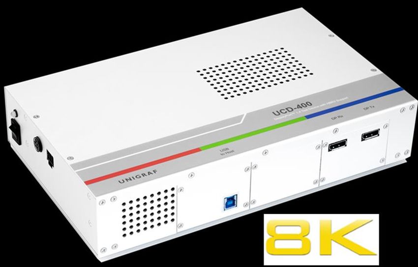
UCD-400
The image below indicates the connections in UCD-400 unit and their description.
Name Description
DP in DisplayPort™ 1.4a compliant input from the upstream Source.
(UCD-411: N/A)
DP out DisplayPort™ 1.4a compliant output to the downstream Sink
Power in +12 Vdc Power Supply Input
Power On/Off Rocker power switch
USB USB 3.0 connection to the host PC
Programmer USB interface for configuring the device FW (behind a cover)
Ethernet Ethernet interface for updating the device FW (behind a cover)
Note Capturing and sourcing high resolution video modes, especially 4K video modes
and the 120 Hz frame rate set stringent requirements on the video cables and
connectors.
Warning In order to avoid damage to the unit and the PC, please always attach the power
cord (Power In) to the unit first, and after that connect the USB cable to the PC.
USB Type-C Interface
UCD-400 delivery package includes a “C to DP Bi-directional Cable” to enable testing of
Sink or Source devices with USB-C interface.
8.
Introduction
Unpacking
The UCD-400 product shipment contains:
• The UCD-400 or UCD-411 unit
• AC/DC Power supply (100 to 240 Vac 50/60 Hz input, +12 Vdc output)
• USB 3.0 compliant cable for host PC connection
• Micro-USB type B compatible cable for FW programming
• USB-C to DP Bi-directional Cable for testing USB-C sinks or sources
Installation Package
The UCD-400 software installation package can be obtained from Unigraf download page
at https://www.unigraf.fi/downloads/
The installation package is a bundle between the components needed for UCD Console and
for TSI SDK. The bundle contains the following items:
• Windows drivers (installed during set up)
• UCD Console software GUI (installed during set up)
• License Manager (installed during set up)
• DSC Test Content and DSC compression tools (optionally installed during set up)
• TSI SDK (optionally installed during set up)
• User Manuals including this document.
In some cases, also the firmware of the unit needs to be updated. If in doubt, please contact
Unigraf.
Note: The software should be installed before connecting the UCD-400 unit in the PC.
Note: System administrator's privileges are required for performing the installation.
Software Installation
Start the installation by running Unigraf Software Bundle Setup.exe
Once the installer has started, a welcome page is displayed. The welcome page shows the
software package release version.
Click Next to continue. The next dialog you need to agree to Unigraf Software End User
License and select the components installed.
Note The size of the DSC Content Library Generator with supporting files is 2.6 Gbytes
Next dialogs define the installation folder in your PC and the Start Menu folder used.
When the selections are ready, click Install to start the installation.
Click Finish to exit the installation dialog.
9.
License Manager

        LICENSE MANAGER
        Licensing
             The features of UCD Console GUI are divided into groups based on the target use of the
             device. Some basic features can be used without licenses. Advanced feature groups have
             their dedicated licenses that open the related part of the GUI or enable the related control.
             Unigraf licenses are provided as strings of characters, License Keys. Each License Key
             enables a dedicated function in one device. Each device has its dedicated Seed Number.
             Each License Key is tied to one Seed Number. License Keys can be freely used in any
             number of PCs
             License keys are managed with Unigraf License Manager. By default, shortcut to Unigraf
             License Manager can be found in Start Menu under: All programs/Unigraf/UCD-400.
             Please click Yes in the first dialog. License Manager can be run only with Administrator
             rights.

Note:        System administrator's privileges are required for accessing the licenses.

        License Manager GUI
             When run, License Manager will list the licensing enabled Unigraf devices. If no suitable
             device families are detected, License Manager will exit. Please first select one of the
             available device families by clicking one of the device family selector buttons.

             In the list of Attached Devices please select the device in question. The serial number and
             the seed number of your device are printed in a sticker attached to the bottom of the device.

             The Back button opens the device family selection screen. The Refresh button will re-scan
             the system for installed hardware.

                                               10.
License Manager
Managing Licenses
Seed Number
Each license is tied to a hardware unit with the help of the Seed Number. Each unit has a
unique Seed Number. Seed Number of the selected unit can be found in the top of the
dialog.
Seed Number of the selected device can be copied from dialog link for e.g. ordering
Licenses.
Adding New License Keys
To add a new license key for a device, please enter the characters from the license sticker to
the boxes provided. The License Manager will automatically move the caret across the edit
boxes during typing. If the key is given in text format, copy it and paste to the leftmost box.
Once the license key is fully entered, click the Install. The license is authenticated and if it
is valid, the license will appear in the list of installed licenses. If the key fails to
authenticate, an error message is displayed. If this happens, please make sure that the key
has been typed correctly and that the seed number on the license key sticker matches the
seed number displayed seed number for the device.
Please note that to avoid confusion, some letters will never appear in a license key because
they resemble numbers: For example, capital 'G' and number '6' are very similar when
printed with small font. When in doubt, use numbers.
Also, please notice, that characters that can't be part of valid license key are not accepted as
input. When appropriate an automatic conversion is applied while typing: For example,
lower case letters are converted to upper case automatically.
Managing Installed Licenses
The Installed licenses list shows all currently installed licenses for the currently selected
device. The list shows the actual license key, and what that key unlocks.
Remove Selected will uninstall selected licenses. To uninstall a license, click on the license
and then click the Remove Selected button.
Export will allow all installed licenses for the currently selected device to be saved into an
INI file for backup and distribution to other PCs. To export a license, click on the license
and then click the Export button. Please notice that licenses from multiple devices can be
exported into the same INI file.
Import will install licenses from an INI file for the currently selected device.
11.Firmware Update Procedure
FIRMWARE UPDATE PROCEDURE
UCD Configuration Utility is used to load an updated firmware to the device. As an option,
UCD Configuration Utility enables the user to select the operation roles present in the
UCD-400 unit. The utility configures a firmware set for the selected operation roles and
programs the firmware set to the device. Please contact Unigraf for details.
Updating from Earlier FW Versions
UCD Firmware versions earlier than 1.8.52 (Pls see Help > About) do not support the
procedure described here. Please update the FW first to version 1.8.52. Please follow
instructions in Appendix G Firmware Update Procedure with Quartus Prime in this
manual.
Warning It is very important to install the firmware included in software version 1.8.52
before trying to update the firmware included in a later version. If any problems
with FW update occur, please revert to version 1.8.52.
Note: Firmware update is a sensitive process. Please do not disconnect the device from the
PC and do not power it off before the operation is completed unless specially
requested. Avoid plugging and unplugging other USB devices when the firmware
update is in progress.
To update the firmware or create a new configuration on a UCD-400 device, please
perform the following steps:
Connect the UCD-400 unit to a power supply and connect the USB cable.
Open UCD Console. Select Tools > Firmware update.
UCD Firmware Configuration tool can alternatively be launched in Start Menu.
The first page of the utility indicates the firmware component versions present in the
package. Please click Next.
12.Firmware Update Procedure
If several UCD units are connected to the PC, in next dialog please select the devices to be
updated. Click Next.
Updated Modules
The tool indicates the firmware file to be used and prompts for selection of the firmware
modules to be updated. It compares the modules in the selected device and omits the ones
that are the same.
When you are done, click Next.
13.Firmware Update Procedure
Updating from Earlier FW Versions
Earlier firmware versions of UCD-400 are not supporting firmware update using
UCD Firmware Configuration tool and must be updated using Quartus Prime tool. When
attempting to update an earlier non-supporting version the tool will display an error
message.
Please refer to Appendix G of this manual for instructions on Firmware Update Procedure
with Quartus Prime.
Once a firmware supporting UCD Firmware Configuration tool has been installed, all
future updates can be done using this tool.
Power Cycle
When re-initiating the firmware of a UCD device the whole process cannot be done during
one session and the UCD device need to be restarted between steps. Therefore, on certain
point, user needs to power cycle the device (switch off power> wait for 10 seconds > turn
on power).
14.Firmware Update Procedure
Click OK button on the dialog.
Note: The procedure may take several minutes depending on the speed of the USB
connection of the host PC.
15.UCD Console
UCD CONSOLE
UCD Console is the graphical user interface (GUI) of UCD-400 for desktop use. It provides
the user access to all features of the unit. UCD Console also includes powerful debugging
and analysis tools enabling the user to monitor the status of the display interfaces and assist
in the problem detection.
The various features of the UCD-400 are divided into interface specific screens and tabs.
Each tab contains data and controls for a specific feature.
Device Selection
A shortcut of UCD Console can be found by default under Start Menu path
All programs/Unigraf/UCD-400. Once UCD Console GUI is launched the dialog provides
a list of UCD-400 devices connected in the PC. Please select the target device by clicking
on the appropriate button. If your device cannot be found in the list, please confirm the
power and USB connection to the device and click the Rescan … button.
Analyzer and Pattern Generator Roles
The use of UCD-400 devices with UCD Console is divided by Analyzer (DisplayPort
Sink), Pattern Generator (DisplayPort Source) and Event Logger (Event Log). The
functionalities of the three roles can be found in tabs. This User Manual will explain all
roles and their functionalities.
When using UCD-411 only Pattern Generator (DisplayPort Source) and Event Logger
(Event Log) roles are available.
16.UCD Console
Warning about DSC Test Content
When running DSC Compliance Tests, UCD-400 needs to have access to DSC content used
as test patterns. The content can be created from the source bitmap files downloaded during
installation (optional) either with Unigraf DSC Content Creator or created by the
Compliance Test Tool on-the-fly during the compliance test.
If Automatically create missing content is selected in Tools > Options menu, but the source
files have not been installed a Warning dialog will open. Clicking OK will open the Option
menu.
You can either re-install the whole SW package with DSC Content Library or deselect
Automatically create missing content in Option menu.
Applying Changes
In various UCD Console dialogues the user needs to update several parameter or fields to
make the changes needed. In order to avoid false combinations of parameters the new
parameters are applied to UCD-400 only after Apply is clicked. In UCD Console the
situation that parameters have been changed but not applied is indicated by bold values of
the parameter.
17.UCD Console
Options
Options can be found in Tools > Options.
Video Audio and Misc. Options
Image File Format
You can save the captured frames either in PPM, BMP or JPG bitmap file format. In PPM
format the files are stored with the captured color depth, with other formats the color depth
is truncated to 8 bits per color.
Audio File Format
Audio files are stored in WAV format
Audio Buffer size
Main buffer: Length of the buffer in the PC memory storing audio samples for monitoring
audio format in DP RX / Audio tab. Increased buffer length will enable longer time span to
be monitored.
Playback buffer: Length in the buffer in the PC for transferring captured audio to PC sound
system. Increased buffer size will ensure a smooth audio output but will also increase the
delay between the capture of the audio stream and its playback.
Folders
Please select the directories in the PC for saving the captured images and audio, the saved
Presets
18.UCD Console
DSC
DSC Work folder: Folder for DSC Work files.
DSC test content directory: Folder where DSC source bitmap files, related configuration
files and DSC conversion tools are stored.
Automatically create missing content: When selected, compliance test tool During
execution of DSC Compliance Tests, the tool automatically creates the DSC compressed
content used for testing the DUT.
Keep auto-created DSC content files: By default, the DSC compressed content is deleted
after use. If selected, the content is not deleted.
Warning Keeping the automatically created DSC compressed content will shorten the time
needed for running the DSC compliance tests.
Please note, that the space needed for storing the full library can be very large
(appr. 400 GBytes). Please make sure that the content will be stored in a medium
that has the required space available.
Misc. options
Apply color conversions to saved images: When saving captured frames, the Color Mode
selected in Video tab will be applied also to saved images.
Bypass 4:2:x –> 4:4:4 conversions: 4:2:2 and 4:2:0 images are previewed and stored as
received, without pixel doubling.
Disable firmware version check: UCD Console lets the user operate a non-matching
Software / Firmware combination. NOT RECOMMENDED.
HDCP protected monitor: Text appearing if the monitor where UCD Console is viewed is
HDCP compliant and HDCP is enabled. This feature enables preview of captured HDCP
encrypted content in Video tab.
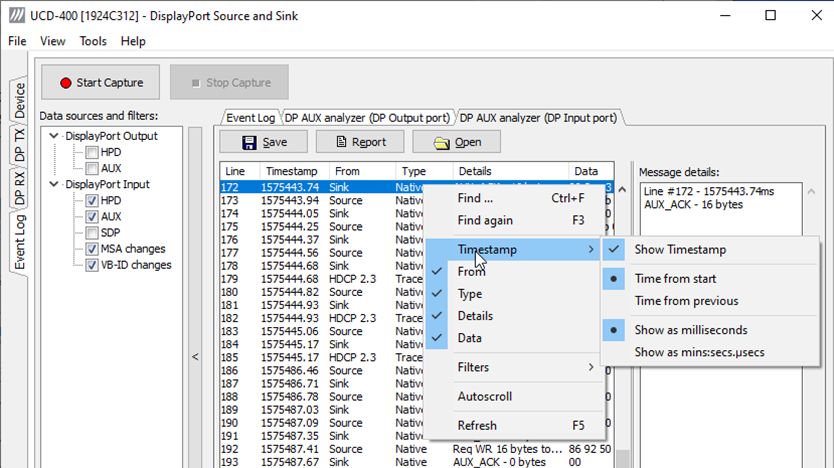
AUX Analyzer Options
Options for configuring the way data is presented in AUX Analyzer tab in Event Log.
Please find full description of the controls in chapter Event Log / DP AUX Analyzer later in
this document.
Detaching Tabs
Most of the UCD Console tabs can be detached into a separate window for monitoring and
controlling separate features simultaneously. To detach a tab Right-click on a tab and
select Detach Page. To glue the tab back to the main window, click on the red Close
button in the top right-hand corner of the window or press + F4 on the keyboard.
19.DisplayPort Reference Sink
DISPLAYPORT REFERENCE SINK
DP Sink functionality not available when using UCD-411.
DisplayPort Reference Sink dialog (DP RX) can be selected from the vertical tab on the left
edge of the GUI. The horizontal tabs on the top of the GUI enable the various functions
available for the input channel. Some of the tabs are enabled by default, some only when an
applicable license is included. DPRX features the following functions.
• Video preview and saving (Video)
• Audio monitoring and saving (Audio)
• Status information and control of the upstream link (Link)
• EDID editor (EDID)
• DPCD editor (DPCD)
• HDCP status monitor and control (HDCP)
• SDP sent by the Source device (SDP)
• FEC feature control and status (FEC)
• Source DUT Testing.
Video Tab
Video tab is the Preview window for the captured DisplayPort stream.
Input video mode
The measured input resolution, frame rate and color format are shown below the preview
window. The indication of the number of frames captured to the PC indicates the pace of
the image data transfer to the PC.
Disable / Enable Preview
Click here the button to start or stop capturing video frames.
20.DisplayPort Reference Sink
The top ribbon of the tab has the following controls:
Color Mode for preview
• No Conversion: The captured color components are interpreted as R, G and B
respectively. No color conversion will be done.
• Automatic: The color mode is selected based on the information in the MSA. If there
is no color information available, “No Conversion” is used.
• YCbCr (ITU-709) - > RGB: The captured data components are interpreted as Y, Cb,
and Cr respectively. Color conversion to RGB is done based on ITU-709 standard.
• SMPTE 170M - > RGB: The captured data components are interpreted as Y, U, and
V respectively. Color conversion to RGB is done based on SMPTE 170M standard.
Note: Please note that the color mode selection applies to the preview window only. All
internal functions use the raw image data as captured from the input channel.
Select Virtual Channel
When Multistreaming (MST) is enabled, the monitored stream can be selected here.
Save one frame
Capture and save one video frame as a bitmap file in the PC. The format and storage
location can be selected in Tools > Options pull-down menu. The available bitmap formats
are PPM, BMP and JPG.
The selections in Tools > Options menu define if the frame bitmap will be stored as
captured from the display interface or if the color mode conversion selected for preview
will be applied.
Sequence recording
Clicking the button opens a dialog for definition of number of frames recorded. Buffered
mode can also be enabled in this dialog.
In buffered mode, all input frames are captured non-drop until the on-board frame buffer
will be full. The dialog also informs the capacity of the buffer with the selected video
mode.
In non-buffered mode, only one input frame is buffered at a time. Frames will be skipped if
the transfer of the data to the PC is slower than the input data rate.
Note: Please note that buffered mode cannot be used when Audio preview is enabled.
21.DisplayPort Reference Sink
Snap preview
When clicked, one frame of the incoming video is captured and shown in a new Snapshot
tab. The captured bitmap can be saved with Save one frame function described above.
Color Information of the Captured Bitmap can be evaluated by placing the mouse cursor
on top of the preview image. The lower right-hand side ribbon of the GUI lists
• Location of the cross cursor on the bitmap
• The intensity of the Red, Green and Blue components of the pixel on the cursor
location
• The HTML HEX color code of the pixel on cursor location
Zoom of the Preview Image can be altered by right clicking on top of the preview image
and selecting between
• Fit Window
• Zoom 25%
• Zoom 50%
• Zoom 100%
• Zoom 200%
• Zoom 500%
While in the Snap preview mode clicking on the “Camera” icon will take additional
snapshots
22.DisplayPort Reference Sink
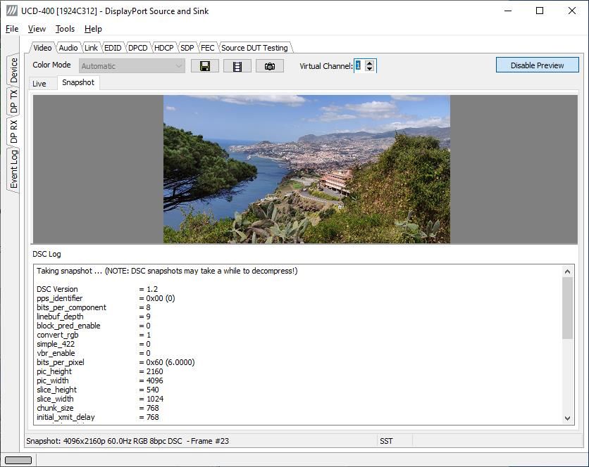
Preview DSC Decompressed Stream
In order to capture and preview DSC compressed video DSC must be enabled by selecting
Link Configuration > Other Capabilities > DSC checkbox in Link tab.
Select Enable Preview to verify that DSC compressed stream is received.
Click Snap a Frame button to capture one frame and start the decompressor (offline in the
PC). Once the decompression is ready, the frame is shown, and DSC Log lists the details of
the compressed image.
23.DisplayPort Reference Sink
Audio Tab
Audio tab has a preview of the audio signal format and the controls for audio playback and
recording. Up to eight channels will be shown based on the received audio stream.
The audio signal format is shown in three ways
• The ‘oscilloscope’ panel displays the waveforms of the received audio channels.
• The frequency spectrum of the audio is shown in the lower panel. The range of the
spectrum display is from 0 to 1/2 of the input sampling rate. The amplitude scale of
the spectrum display can be selected between ‘Linear’ to 80 dB.
• The horizontal sound level indicator is in the bottom of the dialog.
The span of the preview window is defined with Audio preview size found in Tools >
Options dialog. The value is given in ksamples (1024 samples). The relation between the
preview window span in milliseconds (msec) and the value given in Audio preview size
depends on the sampling frequency. Please do not exceed the Audio buffer size set in the
same dialog.
Disable / Enable Preview
This button controls capturing the audio data.
Select Virtual Channel
When Multistreaming (MST) is enabled, the monitored stream can be selected here.
24.DisplayPort Reference Sink
Playback device selection
The captured audio can be played back in the PC. The combo-box defines the audio device
in the host PC through which the captured audio is played. By default, the No audio
playback is chosen.
Note Please note that the audio capabilities of the audio playback device of the PC are not
automatically reflected in the audio capabilities description in UCD-400 EDID.
Since UCD-400 is not performing any audio format conversion, it might occur that
the source provides an audio format that the selected playback device is not
supporting. In case a conflict occurs, please change manually the EDID content or
disable audio playback to monitor the waveforms in UCD Console.
Refresh audio device list
Click here to re-read the list of audio devices after making changes to the host PC
configuration.
Audio Buffer Size
The amount of buffering used in the data transfer between the UCD-400 unit and the PC in
Audio buffer size in Tools > Options dialog. Increased buffer size will ensure a smooth
audio output but will also increase the delay between the capture of the audio stream and its
playback.
Start audio recording
The captured audio can be recorded in the PC using Waveform Audio File Format, WAV
(*.wav) format. The pop-up dialog defines recording duration. The folder where the audio
file will be saved can be selected in File > Options.
Input audio mode
This field (in the bottom of the dialog) indicates detected audio mode in the input stream.
25.DisplayPort Reference Sink
Link Tab
Link tab contains four panels: Cable / HPD, Link Status, Link Configuration and Stream
Status.
Cable / HPD
Indicator lights of the state of the cable. Cable indicates that the hardware has detected an
upstream cable. HPD indicates that the HPD signal is Asserted (logical “high”).
Clicking the Deassert button will cause HPD line to be set to logical “low” (de-asserted)
and hence no HPD pulse can be generated. Click the Assert to re-activate the HPD line (set
to logical “high”).
To apply an HPD Pulse with programmable duration click Pulse HPD. The duration will
be defined in the provided field.
For applying a short pulse click Short Pulse. Pulse duration is 1 ms.
Link Status
Link Status displays the status of the link training and the link parameters negotiated
between UCD-400 Sink and the Upstream Source. The data is retrieved from the DPCD
registers of the UCD-400 Sink. The status is updated automatically.
Link Configuration
Link Configuration allows the user to change the way the Sink capabilities are announced
in the DPCD registers of the UCD-400 Sink. Maximum Lane Count and Maximum Link
Rate are set with their appropriate radio buttons. To update the new status to the DPCD
registers click Apply.
Other Capabilities section includes controls of features like MST, FEC and DSC
Click Enable Fast LT to enable support for a link training without AUX transactions.
When Force cable status to plugged is checked, sink functionality is active regardless of a
failure of upstream device detection e.g. due to incorrect AUX Channel electrical
termination.
26.DisplayPort Reference Sink
To apply a Hot-Plug Detect pulse automatically after updating the status, select Generate
HPD pulse on Apply. HPD pulse duration will be defined in the Pulse HPD field.
Stream Status
Stream status is enabled with UCD Pro for DP Sink license.
Video Timing Details are retrieved from the Main-Stream Attributes (MSA) of the
monitored stream. Frame rate is measured by UCD-400 Local Sink.
Note: Please note that the MSA information used for Video Timing Details is provided by
the Upstream Source, it is not measured by the UCD-400 Local Sink.
CRC
The 16-bit CRC (checksum, cyclic redundancy check) values of the three color
components of the captured video frame; calculated by the Sink hardware. To re-calculate,
click Update Link Status.
The 16-bit DSC CRC values of the captured DSC compressed frame. “Value 0” is
calculated from 1st, 4th, 7th … byte, “Value 1” from 2nd, 5th, 8th … byte and “Value 2” from
3rd, 6th, 9th … byte.
Multistreaming
When Multistreaming (MST) is enabled and the source sends a multi-stream signal the
details of the received virtual channels is shown in a table in Stream Status field.
Port#: Port number where the virtual channel is directed.
Stream ID: Stream identification number of the virtual channel
Req. PBN: Requested PBN (payload Bandwith Number) value for the virtual channel
Alloc.PBN: PBN value allocated for the virtual channel
First slot: Time slot where the first VC Payload for the virtual channel is stored
Slot number: Number of VC Payload slots reserved for the virtual channel.
27.DisplayPort Reference Sink
EDID Tab
EDID Tab provides tools for accessing the EDID of the UCD-400 Sink presented to the
Upstream Source Device. There are three basic functions:
• Load and save EDID data files in the host PC
• Edit the EDID contents
• Program and read the contents of the EDID memory of up to four virtual MST Ports
EDID Files
With Load… and Save as… a hex EDID file can be read and written from the PC. Please
note that the program does not alter the contents of the EDID file or verify its integrity
during load and save operation.
Note Four blocks (512 bytes) of EDID code is read. If the device is not supporting all
four blocks, the non-supported area is replaced with zeroes.
Currently the EDID Editor does not support Display ID. Hex EDID files can
however be modified with the HEX Editor or externally generated hex EDID files
that have Display ID content can be load and programmed into the hardware.
HEX Editor
When EDID content is either loaded from a file or read from the hardware EDID memory,
it is shown in the EDID Data panel on the left hand side of the dialog. EDID contents can
be edited by typing over the existing values. Altered content is highlighted with RED.
Please note that Hex Editor itself does not alter the contents of the EDID data or verify its
integrity.
After editing the data can either be saved to an *.ecd file in the PC with Save as… or
programmed it to the hardware EDID memory with Write.
28.DisplayPort Reference Sink
EDID Editor
EDID Editor is launched in a separate pop-up window. Please see the description of the
EDID editor in Chapter EDID Editor later in this document.
29.DisplayPort Reference Sink
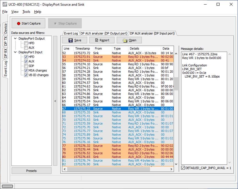
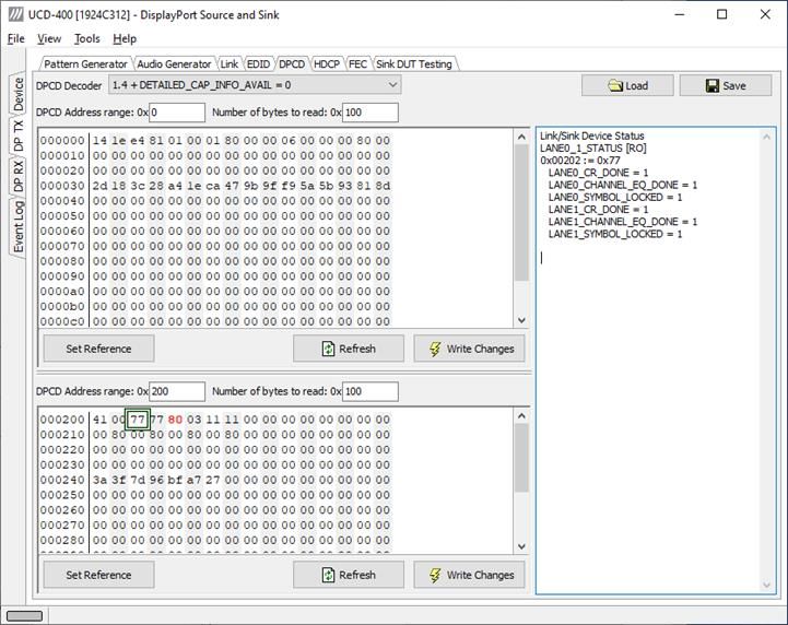
DPCD Tab
DPCD tab is a tool for monitoring and editing the DPCD registers of the UCD-400 Sink.
The tool consists of two independent monitoring and editing windows for the DPCD data.
The user can freely select the the DPCD address areas shown on each panel.
The DPCD Decoder panel on the right hand side shows the interpretation of the DPCD
byte selected on the monitoring windows. The selected byte is shown with a green outline.
The combo box above the DPCD Decoder window allows selection of how the DPCD data
is interpreted. It can be either as DP 1.4 DPCD, or as DP 1.4 DPCD with Detailed
Capability Info selected or not (DETAILED_CAP_INFO_AVAIL = 1/0).
Click Refresh to re-read the data from the DPCD registers to the window in question.
Click Write Changes to write the portion of data shown in the window in question to the
DPCD registers.
Click Set Reference to store currently shown data as a reference for comparison.
30.DisplayPort Reference Sink
When the data is Refreshed from the DPCD registers the changed bytes will be highlighted
with gray background.
The fields edited by the user will be highligted with red color.
Saving and Loading DPCD Content
DPCD data in the selected address areas can be saved as a file in your PC. There are three
alternative formats:
• Binary DPCD Fata File format (*.DPD). This is Unigraf proprietary format. You can
also load the DPCD content stored in this format.
• Comma Separated Values (*.CSV) for loading the data to a spreadsheet.
• HEX Dump (*.HEX) in a human readable text format.
Click Save to select the location and the format of the file.
Click Load to load DPCD data saved in DPCD Data File (*.DPD) format to the editor.
To program the data into the DPCD registers of UCD-400 Local Sink click Write
Changes.
Note - Writing DPCD data to the DPCD registers of the UCD-400 Local Sink will
potentially affect the status and capabilities of UCD-400 as seen by the upstream
source.
- User control like Link Training or mode changes will modify the content of the
DPCD registers
- During a reboot of UCD-400 the DPCD registers will be returned to their default
values
31.DisplayPort Reference Sink
HDCP Tab
HDCP tab is the dialog for monitoring the HDCP (for High-Bandwith Digital Content
Protection) status and controlling the HDCP capabilities of the UCD-400 device.
Status
The status field indicates the HDCP status of the UCD-400 device.
Active: The link between UCD-400 and the upstream source has been encrypted.
Authenticated: The HDCP handshake between the UCD-400 and the sink unit has been
completed successfully.
Declared as HDCP capable: The UCD-400 unit recognizes HDCP handshake messages.
Keys loaded: The HDCP keys are loaded to the UCD-400 unit.
Configuration
HDCP Capable: To disable HDCP uncheck the box.
Keys
Select between Production or Facsimile HDCP keys. To remove the keys, select None.
HDCP 1.3 vs. HDCP 2.3
UCD-400 devices support by default both HDCP 1.3 and HDCP 2.3 standard.
32.DisplayPort Reference Sink
SDP Tab
SDP Tab is enabled with UCD Pro for DP Sink license.
In SDP Tab shows the Secondary-Data Packets sent by the Source device. Click Update to
re-read the data.
SDP Tab displays in hexadecimal format the following received SDP packets:
• Audio_TimeStamp
• Audio_Stream
• Extension
• Audio_CopyManagement
• ISRC (International Standard Recording Code)
• Video Stream Configuration (VSC)
• Camera Generic 0
• Camera Generic 1
• Camera Generic 2
• Camera Generic 3
• Camera Generic 4
• Camera Generic 5
• Camera Generic 6
• Camera Generic 7
• Vendor-Specific Infoframe packet
• AVI InfoFrame packet
• Source Product Descriptor InfoFrame packet
• Audio InfoFrame packet
• MPEG Source InfoFrame packet
• Dynamic Range and Mastering InfoFrame
• Picture Parameter Set (PPS)
33.DisplayPort Reference Sink
FEC Tab
FEC Tab is enabled as a basic feature.
FEC tab contains control of the FEC (Forward Error Correction) feature, Error Detection
table and FEC Status Log.
Enabling FEC
Enabling FEC feature is controlled by the source device. When connected, source verifies
corresponding registers in sink DPCD to find out if sink is FEC capable. This register in
UCD-400 sink can be controlled by FEC Capable checkbox.
Since source normally polls sink DPCD mainly after a new connection, selecting Generate
HPD on change will force a new connection after the change of the FEC capability status.
Click Update to read the FEC Error Counters
Click Clear to clear the counters.
FEC Status Log lists FEC events.
34.DisplayPort Reference Sink
Source DUT Testing Tab
Source DUT Testing Tab is enabled with UCD Pro for DP Sink license.
Please refer to Appendix E later in this document for description of the tests available.
Select the tests for execution by clicking the corresponding row.
Clicking Configure… opens a dialog for defining the test parameters for that set. Please
refer to Test Parameters below for description.
Parameters from Test descriptor files can be loaded with Import and stored with Export.
Please refer to documentation of TSI software API for description.
Tests are started by clicking Run Selected. By clicking Abort the sequence is stopped.
Test flow can be controlled with Repeats of the test sequence, Delay time between
individual tests or Stop on Failure that stops the whole sequence if one of the tests fail.
At the completion of each test the result of the test is indicated in the matrix on the right
hand side of the test panel. For each test the matrix lists the number of occurrences of each
result and the number of tries performed.
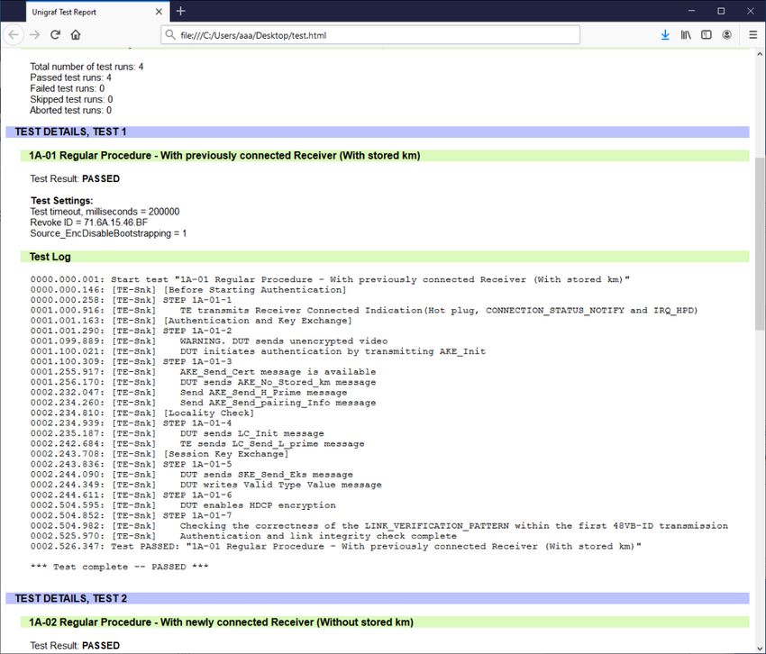
Click Save Report to generate a HTML report file for sharing the results with other parties
for viewing without UCD Console.
By clicking Clear All the test log and the results matrix are cleared.
35.DisplayPort Reference Sink
Test Parameters
Each test set has its dedicated set of test parameters. Open a dialog for defining the
parameters by clicking Configure….
Parameters of Link Layer CTS
Link Layer CTS parameters includes DUT capabilities defined in Source Device Capability
Question List in document DisplayPort Link Layer Compliance Test Specification. The
capabilities are grouped into tabs based on the tested feature.
Parameters of CRC Test Set
CRC Video test parameters dialog contains fields for defining the test duration, number of
frames captured, errors allowed and expected video format.
Click Capture now to record Reference CRCs. Please define the number of frames used as
reference – either one or the number of frames in the predefined test sequence.
36.DisplayPort Reference Sink
Parameters of DP RX Simple LT Tests
The parameters for DP RX Simple LT test set is a subset of DUT capabilities.
Presets
In all parameter dialogs the selected parameters can be saved as Presets. Please click
Presets… to save or recall a configuration.
37.DisplayPort Reference Source
DISPLAYPORT REFERENCE SOURCE
DP Source functionality available when using both UCD-400 and UCD-411.
DP Reference Source function is using one output channel, DisplayPort Source (DP TX).
The corresponding vertical tab can be seen on the left edge of the GUI.
The horizontal tabs on the top of the GUI enable the various functions available for the
output channel. Some of the tabs are enabled by default, some only when an applicable
license is included. DPTX features the following functions.
• Video pattern generator (Pattern Generator)
• Audio generator (Audio Generator)
• Status information and control of the downstream link (Link)
• EDID editor (EDID)
• DPCD monitor (DPCD)
• HDCP status monitor and control (HDCP)
• FEC feature control and status (FEC)
• Sink DUT Testing Tab.
Pattern Generator Tab
Note The video modes that can be used in MST streams are limited by the overall
capability of the DisplayPort link and the capability of the connected DisplayPort
Sink or Branch device.
38.DisplayPort Reference Source
Predefined Timings
UCD-400 includes a set of common predefined video timings. Please find a list of the
timings with their major details in Appendix C of this document.
Color Mode
RGB color mode with full range quantization levels will be used with all patterns except
with Color Square Pattern. This pattern allows the user to select RGB, YCbCr 4:4:4,
YCbCr 4:2:2 and YCbCr 4:2:0 color modes. When YCbCr is selected, the Colorimetry
dropdown box is enabled and allows selection between ITU-709 and ITU-601. Please find a
description of the available test patterns in Appendix D of this document.
Color Depth
You can set the color depth used. The available color depths are: 6, 8, 10, 12 and 16 bpc.
Color depth 6 bpc is only available with RGB.
Predefined Video Patterns
UCD-400 has a set of predefined patterns and a possibility to user defined custom patterns.
The predefined patterns are selected from the list in the combo box. By selecting Disabled
you can have the links activated but no video data transferred.
Please find a description of the available predefined patterns in Appendix D of this
document.
When MST mode is selected, full selection of test patterns is available only in stream 0
Custom Image Patterns
BMP, PNG, JPG and TIFF files can be loaded from the PC to be used as custom images.
The bitmaps will be aligned to the top left hand side corner, displayed at the original
resolution, no scaling, cropped to the active area.
MST Operation
Multi-streaming can be enabled from MST check box and selecting the number of streams.
Note Please note that MST and DSC features and cannot be used simultaneously
Pattern Generator Settings
In order to avoid sourcing invalid video mode combinations new settings are being
validated when the user is clicking Apply. Automatic validation will be applied when
Auto-apply when valid is checked. The situation that parameters have been changed but
not applied is indicated by bold values of the parameter. If new settings cannot be
supported by e.g. the selected link configuration, an error dialog will be shown.
Note Please note that the changes in Pattern Generator tab will not be applied unless the
user validates them by clicking Apply or when Auto-apply when valid is checked.
39.DisplayPort Reference Source
Custom Timing
Custom Timing feature is enabled with UCD Pro for DP Source license.
The timing parameters can be modified by selecting the Custom check-box and editing the
fields of the matrix. Enable the new parameters by clicking Apply button.
Manage Timings
Custom timings can also be created and edited with pop-up Timing Editor. Launch the
editor by clicking Manage Timings.
In order to create a new custom timing based on one of the standard fixed, timings select
the fixed timing and change its name and click Add new timing to store.
In order to modify an existing custom timing, select it, modify and click Update timing.
The dialog will make a sanity check for the values entered and will warn the user for any
combinations that cannot be used.
Customize Timings List
The timings are shown on the pull-down menu by un-checking the Show box. The timings
will remain in the list and can be brought back to the pull-down menu, when needed.
40.DisplayPort Reference Source
Sourcing DSC Compressed Patterns
DSC compressed pattern files can be created with a separate tool called DCS Compressor.
It can be launched from Tools > DSC Compressor.
Select the source bitmap file in Source File field. Define the Output Resolution, the color
depth, compression ratio and number of horizontal and vertical slices in the frame.
Click Start Compressor(s).
A DSC compressed file named e.g. Your_Picture_4096_2160_8.dsc will be created in the
same folder are your source file Your_Picture. The selected resolution and bit depth will be
added to the file name.
Select Enable DSC and click Apply.
Note Please note that the output resolution has to match the size of the used compressed
DSC image.
Note Please note that MST and DSC features and cannot be used simultaneously
41.DisplayPort Reference Source
Audio Generator Tab
Audio generator allows the user to play LPCM audio generated internally or from files in
WAV format.
To load internally generated audio, select Generate audio, and adjust the controls to the
desired audio format.
To load an audio file from your PC, select Load audio from file, click the Open WAV
file… button, browse and select the file and click Open
To play the selected audio content, click the Play button.
The content will be looped until the Stop button is clicked.
Audio Status in the top of the tab indicates the type of the currently played audio content.
42.DisplayPort Reference Source
Link Tab
Link tab shows the status and control items for the DisplayPort link.
HPD
The status LED indicates the state of the HPD signal Asserted (logical “high”) or De-
asserted (logical “low”).
Link status
The panel shows the result of the link training with the connected downstream sink and
status of connection features.
Output Level
Override output level and pre-emphasis values selected during link training. Click Apply
Overrides to validate changes.
Note Please note that connected Sink and Source actively maintain the link. If the
override settings result in link failure, the link will be automatically re-trained and
proper values set.
Link configuration
Set target capabilities for the link training. Click Link Training to apply.
• Set the Number of Lanes used,
• Set the maximum Link Rate,
• Enable Enhanced Framing Mode
• Enable down spreading of link frequency.
Allowed amplitude range is 1 to 10‰ (per mil, 0.1%) (DP 1.4a requirement is 0.5%
maximum)
Allowed Frequency range is 30 to 35 kHz. (DP 1.4a requirement is 30 to 33 kHz)
Click Fast LT to initiate a link training without AUX transactions.
43.DisplayPort Reference Source
Link Pattern
Select between Active video and audio, Idle pattern, or special bit patterns.
When Force Active Video option is selected, character error messages from sink will not
interrupt video transmission.
When Force Idle Pattern is selected, Link Training and Active Video will not be initiated
even after a re-plug.
Note Please note that except Active video, the patterns do not carry video and audio. They
are special bit combinations used for development purposes. When selecting Active
Video (or Force Active Video) normal audio and video are being transmitted over
the link.
CRC
The 16-bit CRC (checksum, cyclic redundancy check) values of the three color
components calculated by the Sink hardware.
The 16-bit DSC CRC values of the captured DSC compressed frame. “Value 0” is
calculated from 1st, 4th, 7th … byte, “Value 1” from 2nd, 5th, 8th … byte and “Value 2” from
3rd, 6th, 9th … byte.
44.DisplayPort Reference Source
EDID Tab
EDID tab enables analyzing and saving the EDID read from the connected Sink device.
There are three basic functions:
• Read the contents of the EDID of the downstream sink over the DisplayPort link.
• Load and save EDID data files in the host PC
• Edit the EDID contents
EDID Files
With Load… and Save as… a hex EDID file can be read and written from the PC. Please
note that the program does not alter the contents of the EDID file or verify its integrity
during load and save operation.
Note Four blocks (512 bytes) of EDID code is read. If the device is not supporting all
four blocks, the non-supported area is replaced with zeroes.
Currently the EDID Editor does not support Display ID. Hex EDID files can
however be modified with the HEX Editor or externally generated hex EDID files
that have Display ID content can be load and programmed into the hardware.
HEX Editor
When EDID content is either loaded from a file or read from the hardware EDID memory,
it is shown in the EDID Data panel on the left hand side of the dialog. EDID contents can
be edited by typing over the existing values. Altered content is highlighted with RED.
Please note that Hex Editor itself does not alter the contents of the EDID data or verify its
integrity.
After editing the data can either be saved to an *.ecd file in the PC with Save as… or
programmed it to the hardware EDID memory with Write.
45.You can also read