Lining up the approach: RN prepares for F- 35B trials on Queen Elizabeth - Jane's
←
→
Page content transcription
If your browser does not render page correctly, please read the page content below
Lining up the approach: RN prepares for F-
           35B trials on Queen Elizabeth
                              [Content preview – Subscribe to Jane’s Defence Weekly for full article]

Preparations are well advanced on both sides of the Atlantic for F-35B flight trials to be
conducted on HMS Queen Elizabeth in the latter part of 2018. Richard Scott reports

Later this year HMS Queen Elizabeth , the first of the UK Royal Navy’s (RN’s) two new 65,000-ton
Queen Elizabeth-class (QEC) aircraft carriers, will embark a pair of fully instrumented Lockheed
Martin F-35B Lightning II short take-off and vertical landing (STOVL) Joint Strike Fighters (JSFs) for
fixed-wing first-of-class flying trials (FOCFT) off the eastern seaboard of the United States. It is
planned that these development aircraft, drawn from the F-35 Patuxent River Integrated Test Force
(ITF), will operate from the ship for two four-week periods split by a week of downtime.

 HMS Queen Elizabeth is planned to commence first-of-class flying trials with the F-35B off the
 eastern seaboard of the United States in October 2018. (Aircraft Carrier Alliance)
                                                                                       1717478
The integration of the F-35B and the QEC aircraft carrier presents the United Kingdom with a unique
opportunity and a complex challenge. The fact that the aircraft and ship are both new means it has
been possible, to a great extent, to optimise the QEC design as a bespoke, well-found maritime
operating base for the fifth-generation F-35B aircraft. At the same time there are a number of
uncertainties arising from the fact that design, development, and demonstration activities for the F-
35B and QEC have effectively been run in parallel, albeit with a number of excursions en route.

 © 2018 IHS. No portion of this report may be reproduced, reused, or otherwise distributed in any form without prior written        Page 1 of 8
 consent, with the exception of any internal client distribution as may be permitted in the license agreement between client and
 IHS. Content reproduced or redistributed with IHS permission must display IHS legal notices and attributions of authorship. The
 information contained herein is from sources considered reliable but its accuracy and completeness are not warranted, nor are
 the opinions and analyses which are based upon it, and to the extent permitted by law, IHS shall not be liable for any errors or
 omissions or any loss, damage or expense incurred by reliance on information or any statement contained herein.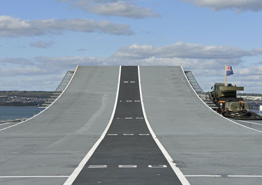
This will be the first time in almost 40 years that the United Kingdom has integrated a new carrier
and a new carrier-borne fast jet aircraft. Moreover, the ship/air interface will be significantly more
complex and challenging than that of the previous-generation Invincible-class carriers (CVSs) and
the Sea Harrier/Harrier STOVL fighters they embarked.

That complexity is in part explained by the size of the ships and the number of aircraft they will be
able to embark and partly by the data extraction requirements of the F-35 autonomic logistics IT
system. It is also a reflection of the extremely harsh operating environment that will be encountered
on the QEC flight deck, specifically the aero-thermal, acoustic, and jet-wash effects created by the
F-35B. This brings additional management challenges to ensure the health and safety of personnel
operating in this inherently hazardous environment.

                                                           [Continued in full version…]

 An F-35B is taxied on the flight deck of amphibious assault ship USS America (LHA 6).
 Previous F-35B carrier suitability and integration on USS America and USS Wasp is informing
 FOCFT on Queen Elizabeth . (US Navy)
                                                                                      1717483
Operating envelope

Ship/air integration requires FOCFT to validate design modelling and support the production of the
full ship/air integration release. In order to achieve these objectives the aircraft must be operated in
a wide range of load, motion, wind, and environmental conditions, coupled with the use of
instrumentation to capture detailed trials data that can be used to define the limits of the safe
operating envelope.

 © 2018 IHS. No portion of this report may be reproduced, reused, or otherwise distributed in any form without prior written        Page 2 of 8
 consent, with the exception of any internal client distribution as may be permitted in the license agreement between client and
 IHS. Content reproduced or redistributed with IHS permission must display IHS legal notices and attributions of authorship. The
 information contained herein is from sources considered reliable but its accuracy and completeness are not warranted, nor are
 the opinions and analyses which are based upon it, and to the extent permitted by law, IHS shall not be liable for any errors or
 omissions or any loss, damage or expense incurred by reliance on information or any statement contained herein.
This means carrying out sufficient launches and recoveries in varying conditions of ship motion,
relative wind, and relative headings to establish safe operating conditions by day and night;
establishing safe operating limits for the ship and aircraft; measuring the dynamic forces and
accelerations induced in the undercarriage during landing and take-off; and measuring the control
margins while operating under a wide variety of conditions.

RN Commander Nathan Gray is one of three UK pilots who will execute the FOCFT on board Queen
Elizabeth (the others being Royal Air Force test pilot Squadron Leader Andy Edgell and BAE
Systems’ F-35 STOVL lead test pilot, Pete ‘Wizzer’ Wilson). A former Sea Harrier pilot who later
flew the Harrier GR7/9 and, on exchange, the US Marine Corps AV-8B Harrier II, Cdr Gray currently
serves as a developmental test pilot in the ITF at NAS Patuxent River.

                                                           [Continued in full version…]

Test points

David Atkinson, BAE Systems’ aircraft-to-ship integration lead, expanded on the progress being
made against the test plan. “As a team, we are developing the detailed test points that we need to
achieve and where they need to be around the operating envelope that we believe we’re going to
be able to release to service,” he said. Explaining that testing will become incrementally more
complex, he added, “We will start from the initial ‘heart’ of the envelope, where we always start
testing, and we will progress out to the edges of the envelope that we need to reach to give the
maximum capability from the F-35B when operating from Queen Elizabeth .

“This has been a progressive piece of work that we started in around 2009, when we laid out the
outline plan and the aspirational envelopes, which were the maximum that we expected to be able
to achieve from our knowledge of the F-35B aircraft and Queen Elizabeth and what we knew about
the ship’s performance at sea and the capability to generate wind-over-the-deck,” Atkinson told
Jane’s , underlining that all of those “are important parameters in determining the operating
envelope”.

“In the March through to December 2017 period we conducted a very intensive set of flight simulation
trials to provide evidence that we are using now to underpin what we believe the test envelopes
should be for flight trials,” he added.

Piloted simulation has formed an important part of the ship/air integration process over a number of
years. In 2017 BAE Systems commissioned a new facility at Warton to replace the previous motion
dome simulator used to support earlier phases of F-35/QEC integration activity.

The new simulator, which represents an investment of about GBP2 million (USD2.8 million), includes
a fully representative F-35 cockpit mounted on a six-axis electric motion system housed inside a
fixed 3.65 m radius dome. The cockpit is an accurate replica of the F-35B cockpit, including active
sidestick and throttle units, a large-area touchscreen display and ejection seat model, all of which
are the same standard as those employed in the F-35 full mission training simulators. A flight-
standard helmet-mounted display system has also been integrated to provide pilots with flight
guidance and navigation symbology.

                                                           [Continued in full version…]

 © 2018 IHS. No portion of this report may be reproduced, reused, or otherwise distributed in any form without prior written        Page 3 of 8
 consent, with the exception of any internal client distribution as may be permitted in the license agreement between client and
 IHS. Content reproduced or redistributed with IHS permission must display IHS legal notices and attributions of authorship. The
 information contained herein is from sources considered reliable but its accuracy and completeness are not warranted, nor are
 the opinions and analyses which are based upon it, and to the extent permitted by law, IHS shall not be liable for any errors or
 omissions or any loss, damage or expense incurred by reliance on information or any statement contained herein.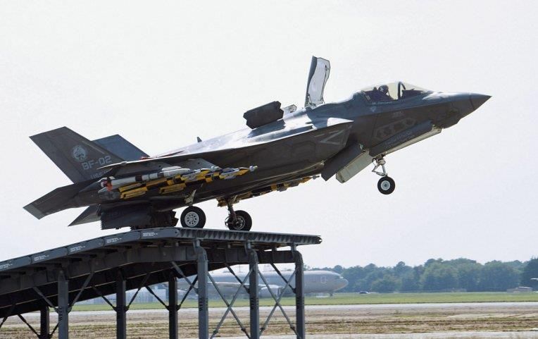
Simulator scene: the LSO’s view from the FLYCO, with an F-35B coming alongside for a
 vertical recovery. (BAE Systems)
                                                                                    1717481
Two strands

According to Atkinson, there are two key strands of work under way ahead of FOCFT. “First,
Lockheed Martin and ourselves are preparing the flight clearance evidence to NAVAIR and then will
provide a flight clearance recommendation to the MoD,” he explained. “The MoD will then take that
forward through the airworthiness and naval authorities to obtain permission to conduct those flight
tests.”

The other aspect is developing the fine detail of the individual test points and the overall test plan.
“That will go through the test authorities in exactly the same way as any test plan goes through for
the F-35 test team,” said Atkinson, explaining, “so it will go through a test readiness review, and then
it will go to an executive review.”

“We’re also working much broader on exactly where in the ship and what facilities in the ship the
test force need to use and where the equipment is going to come from to support the aircraft,” he
added. “There is a huge amount of detail and lots of planning across all the different lines of
development that are touched by a deployed aviation operation.”

Atkinson went on to emphasise the detailed planning process that is under way. “The detail of each
of those areas is being planned within Navy Command by the Carrier Strike Group,” he said. “We
are feeding information and evidence to inform that and to ensure that we have a complete kit of
parts to support the aircraft and to connect the aircraft from both physical and data points of view.
That includes fuelling, electrical power supplies, maintaining the aircraft in the hangar, and extracting
data from it.”

“We’re there to collect flight test evidence,” he continued. “The data extract, and the way the flight
test aircraft are configured to allow us to conduct the tests, is critically important.

Additionally, the two F-35Bs operating from Queen Elizabeth for FOCFT will both telemeter data
back to the ship, so we will temporarily fit a telemetry system to the ship.”

FOCFTs naturally start in the middle of the envelope, in the most benign conditions. “We have
already done months of simulator work at BAE Systems at Warton,” said Cdr Gray, “to do those
steps to find out where the edge of the envelope is.

“We are so far beyond where we were 20 or 30 years ago,” he suggested. “That enables us to
predict where we are going to next – and it enables us to validate exactly where we are, how safe
we are operating, [and] how close to the boundary we are. Our most recent [ski-jump] testing has
shown that the aircraft reacts in exactly the same way as the model.”

                                                           [Continued in full version…]
 © 2018 IHS. No portion of this report may be reproduced, reused, or otherwise distributed in any form without prior written        Page 4 of 8
 consent, with the exception of any internal client distribution as may be permitted in the license agreement between client and
 IHS. Content reproduced or redistributed with IHS permission must display IHS legal notices and attributions of authorship. The
 information contained herein is from sources considered reliable but its accuracy and completeness are not warranted, nor are
 the opinions and analyses which are based upon it, and to the extent permitted by law, IHS shall not be liable for any errors or
 omissions or any loss, damage or expense incurred by reliance on information or any statement contained herein.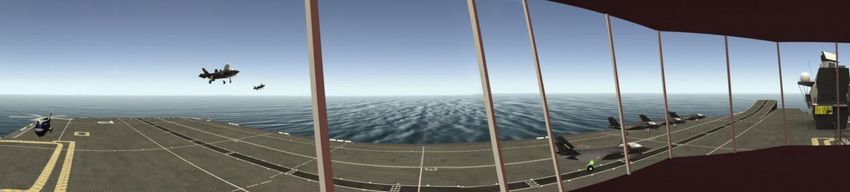
Ski ramp

As part of the F-35 system design and development phase, a land-based ski ramp – modelled on
the legacy 12° design used in the RN’s earlier CVSs – was constructed in 2009 by WFEL at NAS
Patuxent River to support UK testing. By the end of 2010 it seemed the equipment would be
rendered redundant after the UK MoD decided to switch to the F-35C carrier variant (CV), but the
ski ramp was, fortuitously, still in place by the time that decision was itself reversed in May 2011 to
revert back to the F-35B STOVL variant.

A first ski-ramp launch was performed in June 2015 and by the end of June 2016 31 ski-ramp short
take-offs (STOs) had been performed to complete Phase 1 testing. Test aircraft BF-01 and BF-04 –
both instrumented to measure landing gear loads – were used for testing with internal stores only.

Speaking to Jane’s in 2017, BAE Systems test pilot Pete Wilson explained, “We learned that we had
excellent models that did a good job of predicting how ski-jump STO mode performs. However, we
saw a couple of imperfections in the modelling that we have now corrected and we also found that
we were not positioning the nozzles in the optimum position under all circumstances, which has
allowed us to tweak the control law and improve the mode.”

Phase 2 ski-jump STO trials began at Patuxent River in June 2017. While Phase 1 was essentially
a de-risking exercise, with internal stores only, Phase 2 incorporated the bulk of the test points
required to expand the ski-jump envelope.

 Phase 2 ski-jump trials with the F-35B were completed at NAS Patuxent River in 2017.
 (Lockheed Martin)
                                                                                                                                    1717479
“The second trials [allowed us] to evaluate handling characteristics with external weapons, including
asymmetric weapon loads, crosswinds, and overspeed/underspeed take-offs,” said Wilson. “The
results will be used to allow us to take relatively big steps during FOCFT, which means we’ll get
through the testing at the ship much quicker and with much lower risk.”
 © 2018 IHS. No portion of this report may be reproduced, reused, or otherwise distributed in any form without prior written        Page 5 of 8
 consent, with the exception of any internal client distribution as may be permitted in the license agreement between client and
 IHS. Content reproduced or redistributed with IHS permission must display IHS legal notices and attributions of authorship. The
 information contained herein is from sources considered reliable but its accuracy and completeness are not warranted, nor are
 the opinions and analyses which are based upon it, and to the extent permitted by law, IHS shall not be liable for any errors or
 omissions or any loss, damage or expense incurred by reliance on information or any statement contained herein.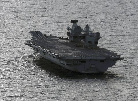
What land-based testing did not fully replicate was the ski ramp on Queen Elizabeth . “The Pax ramp
is actually modelled on the 12°, 150 ft CVS ramp profile,” Wilson pointed out. “ Queen Elizabeth has
a longer [200 ft] two-part ramp angled at 12.5°, so there will be a little bit of the unknown there.

 Queen Elizabeth has a 200 ft two-part ski ramp angled at 12.5°: a longer ramp than the RN’s
 previous CVS carriers, which were angled at 12°. (Richard Scott/NAVYPIX)
                                                                                       1717480
                                                           [Continued in full version…]

SRVL testing

While ski-jump launch and VL envelopes will be prioritised in the early part of the test programme,
SRVLs have also been included in the plan. “For the first four weeks we will be looking to do vertical
landings in fairly benign sea states, working up to higher sea states and then into rolling vertical
landings,” Cdr Gray told Jane’s . “Our ambition is to include SRVL in the first portion of testing.”

Pilots making a vertical recovery will use a glide slope and long-range line-up indicator system
incorporating two Advanced Stabilised Glide Slope Indicators (ASGSIs). The two ASGSI projectors,
situated one forward and one aft on the port side of the flight deck, provide a long-range line-up
indication.

The execution of an SRVL has required the development of a quite different VLA known as the
‘Bedford Array’. Originated and initially prototyped by QinetiQ, the Bedford Array uses software-
controlled LED lights in the deck tramlines to provide a stabilised glidepath alignment cue and a
forward and aft limit line to F-35B pilots carrying out SRVL approaches.

 © 2018 IHS. No portion of this report may be reproduced, reused, or otherwise distributed in any form without prior written        Page 6 of 8
 consent, with the exception of any internal client distribution as may be permitted in the license agreement between client and
 IHS. Content reproduced or redistributed with IHS permission must display IHS legal notices and attributions of authorship. The
 information contained herein is from sources considered reliable but its accuracy and completeness are not warranted, nor are
 the opinions and analyses which are based upon it, and to the extent permitted by law, IHS shall not be liable for any errors or
 omissions or any loss, damage or expense incurred by reliance on information or any statement contained herein.
“The Bedford Array will give us a geostabilised approach for the SRVL so we maintain on glide slope
whatever the ship is doing in the higher sea states,” said Cdr Gray. “We also have the LSO [in the
FLYCO], who is absolutely critical to flight safety.
“The SRVL [approach] is a very precise profile, which needs to be flown to make it safe and
repeatable, so the LSO … will have all the technology, with the glide slope scale, to talk us down
and, if necessary, to wave us off so we can go back around and re-attempt.
“From our simulator trials we’re confident [that SRVL is] going to be safe and effective,” he continued.
“It will allow us to bring back considerably more weapon payload or fuel. If it’s fuel then that makes
it inherently safer to operate because it gives us the option to divert, or maybe to make another
approach.”
Even so, as Atkinson pointed out, there remains an element of the unknown when it comes to SRVL.
“We have conducted a lot of work on the manoeuvre in the simulator, but we have never flown an
SRVL with an F-35 to a real ship before,” he noted, warning that “in that case we must progress
cautiously; SRVL is in a very different state of maturity than vertical landing.
“In the latter case we are absolutely confident we know the capability we can obtain and possibly
extend beyond what is already available on the US Navy’s LHDs [landing helicopter dock
amphibious ships] because our islands are so much further away from our landing spots, so the
airflow characteristics over the deck for a vertical landing ought to be good.”
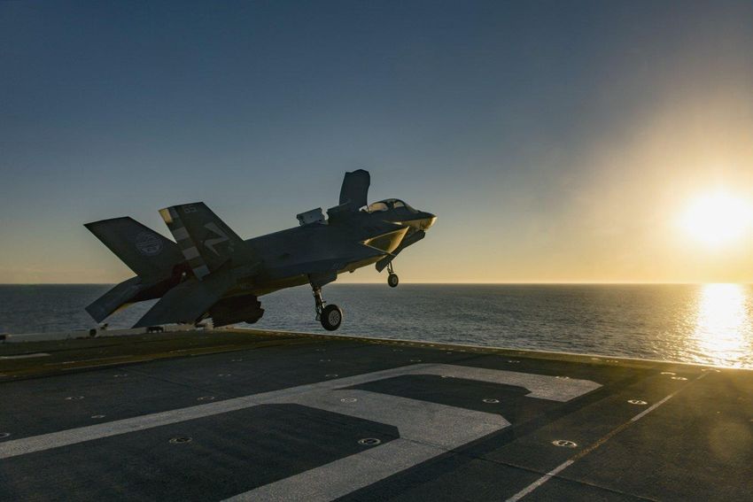
An F-35B completes a short take-off from the deck of the US Navy amphibious assault ship
USS America (LHA 6) in November 2016. While previous F-35B carrier suitability and
integration on USS America and USS Wasp is informing the FOCFT test plan, the ski-jump
STO and SRVL recovery manoeuvre will both be performed at sea for the first time from Queen
Elizabeth . (US Navy)
1717482
© 2018 IHS. No portion of this report may be reproduced, reused, or otherwise distributed in any form without prior written Page 7 of 8
consent, with the exception of any internal client distribution as may be permitted in the license agreement between client and
IHS. Content reproduced or redistributed with IHS permission must display IHS legal notices and attributions of authorship. The
information contained herein is from sources considered reliable but its accuracy and completeness are not warranted, nor are
the opinions and analyses which are based upon it, and to the extent permitted by law, IHS shall not be liable for any errors or
omissions or any loss, damage or expense incurred by reliance on information or any statement contained herein.[Continued in full version…]
For the full version and more content:
Jane's Defence Industry and Markets Intelligence Centre
This analysis is taken from Jane’s Defence Industry & Markets Intelligence Centre, which provides
world-leading analysis of commercial, industrial and technological defence developments, budget
and programme forecasts, and insight into new and emerging defence markets around the world.
Jane’s defence industry and markets news and analysis is also available within Jane’s Defence
Weekly. To learn more and to subscribe to Jane’s Defence Weekly online, offline or print visit
http://magazines.ihs.com/
For advertising solutions visit Jane’s Advertising
© 2018 IHS. No portion of this report may be reproduced, reused, or otherwise distributed in any form without prior written Page 8 of 8
consent, with the exception of any internal client distribution as may be permitted in the license agreement between client and
IHS. Content reproduced or redistributed with IHS permission must display IHS legal notices and attributions of authorship. The
information contained herein is from sources considered reliable but its accuracy and completeness are not warranted, nor are
the opinions and analyses which are based upon it, and to the extent permitted by law, IHS shall not be liable for any errors or
omissions or any loss, damage or expense incurred by reliance on information or any statement contained herein.You can also read