MICRO MARS: A LOW COST MISSION TO PLANET MARS WITH SCIENTIFIC ORBITER AND LANDER APPLICATIONS
←
→
Page content transcription
If your browser does not render page correctly, please read the page content below

MICRO MARS: A LOW COST MISSION TO PLANET MARS WITH SCIENTIFIC
                 ORBITER AND LANDER APPLICATIONS
                         L. Kerstein (1), B. Bischof(1), H. Renken(1), H. Hoffmann(2), U. Apel(3)
          (1)
                EADS Space Transportation GmbH, Bremen, Germany, e-mail: bernd.bischof@space.eads.net
                (2)
                    DLR, Institute of Planetary Research, Berlin, Germany, e-mail: harald.hoffmann@dlr.de
                       (3)
                           Hochschule Bremen, Bremen, Germany, e-mail: uapel@fbm.hs-bremen.de

ABSTRACT                                                      The light-weight micro lander is a challenging
                                                              technological experiment by itself. It is equipped with
The proposed Micro-Mars mission can contribute                a suite of scientific instruments which will
substantially to the international Mars exploration           supplement the orbiter measurements and
program within the framework of a future low cost             concentrate on the environment (temperature cycle,
mission. The concept consists of an orbiter                   atmosphere, magnetosphere and radiation).
integrating a total scientific payload of 30 kg
including a light-weight lander of 15 kg. The                 1.       INTRODUCTION
spacecraft will be launched as piggyback payload by
an Ariane-5 ASAP with a total launch mass of                  In the year 2000, DLR Berlin as prime investigator
360 kg. It will use a bipropellant propulsion system          and EADS Space Transportation GmbH, Bremen as
with 210 kg of fuel and four thrusters of 22 N, and           prime contractor for the space segment started the
four of 10 N for orbit and attitude control. Further          idea of a small, low-cost mission to Mars with a total
attitude actuation shall be performed by three                launch mass of about 360 kg on the ASAP-5
reaction wheels and a gyropackage, a star sensor              platform [1]. Meanwhile, we have performed a
and a sun sensor for attitude sensing.                        phase A study under contract of the German Space
Communication will be performed in S- and X-band              Agency (DLR Bonn), together with DLR Berlin as PI,
to earth and in UHF between orbiter and lander.               several German Universities (Berlin, Braunschweig,
                                                              Bremen, Köln, Mainz, München, Münster),
From a highly elliptical orbit with a periapsis below         MPI Mainz and DLR Köln for the scientific payload,
200 km, four instruments will perform high-resolution         and      two       additional    partners,     EPFL
remote sensing observations and the payload                   Lausanne/Switzerland and MD Robotics/Canada.
consists of a camera system, a magnetometer, a
dosimeter, and an ultrastable oscillator for radio
science.

                                        Figure 1: Micro-Mars mission scenario
For the baseline mission scenario (figure 1), a             •                        Support probable other Martian lander missions
launch in 2007 was assumed with Ariane-5                                             by providing the capability of telemetry contact
piggyback (ASAP 5) using one mini-adapter launch            •                        Unique capability to perform high resolution
opportunity. The 360 kg spacecraft allows a 15 kg                                    remote sensing observations of Deimos (as well
payload for the Mars orbiter and an additional very                                  as Phobos)
small micro lander of about 15 kg total mass for a
soft landing on the Martian surface. The lander shall       3.                                     MISSION ARCHITECTURE
allow for a payload mass of about 2 kg and a lifetime
of > 1 week, whereas the orbiter shall be designed          The overall main objective of this mission is to
for a lifetime of 3 years including the 11 months           provide a small and low-cost system. Therefore, the
journey to Mars. Mission operation is based on one          entire low-cost project is driven by the design-to-cost
ground station, allowing for a maximum of 8 hours           philosophy which requires to launch the spacecraft
contact time between the orbiter and the earth              by a piggyback opportunity - in this case by
station for communication and data downlink.                ASAP 5 - into GTO. The Micro-Mars mission
                                                            architecture consists of the following elements:
2.      SCIENTIFIC OBJECTIVES
                                                            •                        Launch into GTO by Ariane-5 piggyback
The Micro-Mars orbiter and lander mission has to be         •                        Mars orbiter including its payload
seen within the framework of the international Mars         •                        Mars lander including its payload
exploration program. This was taken into account by         •                        Mission control center and one ground station
defining its scientific goals and by selecting the
baseline payload.        Small satellite missions like
                                                                                                                        Bitrate Weilheim/New Norcia
Micro-Mars are very well suited to close existing
gaps in and to provide complementary data to the
                                                                                   160E+6

ongoing exploration effort. This has led to the formu-                             140E+6

lation of the scientific objectives as:                                            120E+6
                                                                                                                  New Norcia ESA

                                                                                                                  Weilheim DLR
• Characterization and investigation of small-scale                                100E+6

     surface features and related geologic processes
                                                                 Bitrate [bit/d]

     through very high resolution imaging from orbit                                80E+6

     in the decimeter-resolution range                                              60E+6

• Refinement of the Martian magnetic field and its                                  40E+6

     anomalies from orbit and determination of                                      20E+6

     magnetic field properties on ground
• Local and regional measurements of the Martian                                   000E+0
                                                                                      01. Aug 08     30. Nov 08         01. Apr 09   01. Aug 09   30. Nov 09   01. Apr 10   01. Aug 10

     gravity field
• Detailed analysis of the atmosphere by radio              Figure 2: Daily data dump to earth for the ground
     sounding, imaging, and in-situ measurements on         stations at Weilheim and New Norcia
     the Martian surface
• Detailed investigation of the ionosphere by               The Micro-Mars orbiter with the integrated lander
     measuring the magnetic field in orbit and on           uses a propulsion system responsible for the Mars
     ground as well as by radio sounding                    transfer injection, the correction manoeuvers and the
• Investigation of the galactic and solar radiation         Mars capture manoeuver into a 3-days Mars orbit.
     environment during cruise, in Mars orbit and on        This will be followed by a release manoeuver for the
     ground                                                 Mars lander and an orbit change manoeuver
• Preparation for future unmanned and manned                controlled by the mission control center located at
     landing missions by:                                   DLR GSOC with its own ground station. Daily
     - Characterization and provision of context            contact time of about 8 hours for the scientific data
          information for future landing sites from orbit   dump to earth will be available (figure 2). The Mars
     - Determination of the biologically effective          micro lander will collect scientific data for some days
          radiation during cruise, in orbit around Mars     and will transmit them to the orbiter during its
          and by in-situ measurements                       contact times.
     - Improvement in our understanding of the
          environmental conditions on the Martian           4.                                     ORBITER SCIENTIFIC EXPERIMENTS
          surface (temperature cycle, atmospheric
          properties, opacity)                              The Micro-Mars orbiter payload consists of four
                                                            different instruments which are described in more
                                                            detail below. The power supply for each of the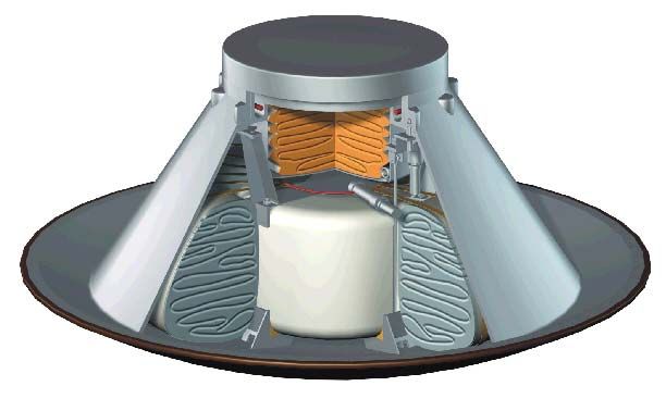
instruments is provided by the spacecraft power          the front row between the two detectors is closed by
subsystem resulting in a major mass saving for the       the second row. The CCDs of the rows overlap
orbiter payload. Additional reductions could be          yielding an effective detector area of 2800 x 1024
achieved by integrating some of the instrument           pixel. At periapsis altitudes of 200 km, the resulting
electronics within the onboard data handling system.     spatial resolution will be 0.45 m/pixel.
A summary of the payload mass and power budgets
is given in table 1. Concerning the power, it has to     Medium Resolution Camera: It consists of the optics
be noted that not all of the instruments will be         with baffle, a filter wheel with 6 positions and the
operating in parallel and that the imaging system will   sensor electronics. The optics is a 400 mm focal
be only switched on for a maximum of 30 minutes.         length telescope with an aperture of 60 mm which is
                                                         build in C/SiC. The modular detector and sensor
  Experiment               Mass [kg]   Power [W]         electronics integrates the focal plane assembly with
  Very-High Res. Imager    9.20        10.0
                                                         the CCD-detector and the sensor electronics into a
                                                         compact 3-dimensional multi-chip module. The
  Medium-Res. Camera       1.50        2.1
                                                         detector is a fast frame-transfer CCD with
  Low-Res. Camera          0.30        2.1               1024 x 1024 pixel and a radiometric resolution of
  Digital Unit (Camera)    1.40        7.0               14 bit. The resulting spatial resolution at 200 km is
  Magnetometer             0.50        0.6               6.5 m/pixel.
  Magnetometer Boom        0.25        n.a.
                                                         Low Resolution Camera: In order to allow for two
  USO Radio Science        0.50        4.0               color imaging which is needed to discriminate
  Dosimeter                1.50        3.0 – 5.0         between bright dust, ices and condensates, the Low
  Orbiter payload total    15.15       28.8 – 30.8       Resolution Camera consists of two identical
                                                         cameras, but each equipped with a different color
                                                         filter (blue and red, respectively). The detector is a
Table 1: Orbiter experiments mass and power
                                                         1k x 1k APS CMOS detector resulting in reduced
budgets
                                                         system complexity and power demands. The optics
                                                         has a focal length of 30 mm yielding a spatial
4.1      MICRO-MARS IMAGING SYSTEM
                                                         resolution of about 2.3 km at 10,000 km altitude.
                                                         Spatial resolution and SNR are by far sufficient to
The Micro-Mars imaging system comprises three
                                                         meet its scientific goal of weather monitoring.
different    camera     heads     with    the    Very
High-Resolution Imager, the Medium Resolution
                                                         4.2     MICRO-MARS MAGNETOMETER
Camera and the Low Resolution Camera.
A common digital unit performs all tasks of camera
                                                         The Micro-Mars magnetometer consists of a triaxial
control and command, data processing and data
                                                         fluxgate sensor with associated sensor electronics
compression. Wavelet data compression is
                                                         and a digital processing board. It is mounted on a
performed off-line by a signal processor and the
                                                         boom with deploy mechanism in order to improve
digital unit has an internal buffer of 3 Gbit to store
                                                         the measurement quality. The magnetometer range
the raw image data before compression. It is a box
                                                         is ± 2000 nT and the inherent resolution is 10 pT.
with the dimensions of 150 mm x 75 mm x 50 mm
                                                         The electronics are integrated within the orbiter data
and a mass of 1.4 kg.
                                                         handling system. Similar fluxgate sensors were
                                                         already successfully flown e.g. on Phobos, Integral,
Very High-Resolution Imager: It is equipped with a
                                                         and DS1 and are also part of the Rosetta payload.
light-weight telescope (Richy-Chretien) with an
                                                         No DC magnetic cleanliness is planed. The high
effective focal length of 4 m and an aperture of
                                                         elliptic orbit implies the chance to calibrate the
40 cm. It is manufactured from C/CsiC to reduce
                                                         instrument in-flight. Special measures for magnetic
mass. Its length is 500 mm. The sensor electronics
                                                         cleanliness are not required.
is based on the development at DLR for the ROLIS
camera onboard the Rosetta Lander and for the
                                                         4.3     MICRO-MARS RADIOSCIENCE
SRC of the HRSC experiment onboard Mars
Express. The focal plane is equipped with 3 interline
                                                         Two radio link modes are used to perform the radio
CCD area arrays with 1024 x 1024 pixel. This
                                                         science experiments:
enables the short integration time of about 0.1 msec.
Time-delayed-integration (TDI) is applied to improve     • Two-way mode: the ground station transmits an
the SNR and to reduce the optics requirements. The           X-band uplink signal, received by the spacecraft
3 detectors are arranged in two rows of 2 and                and transponded coherently back to Earth at two
1 CCD, respectively, in such a way that the gap in           downlink radio signals at X-band and S-band.
                                                             The frequency stability of the radio link is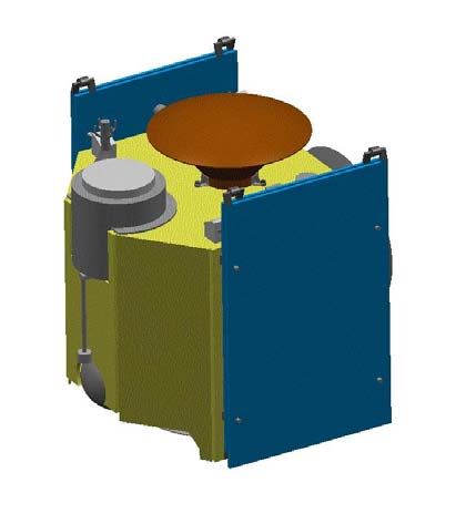
governed by the hydrogen maser of the ground        discriminate against photons. The scintillator is
      station.                                            sensitive to neutrons with energies > 1 MeV.
•     One-way mode: the spacecraft transmits at two
      simultaneous       and     coherent    downlink     The volume of the entire Dosimeter experiment
      frequencies at X-band and S-band. The               including electronics is 100 mm x 100 mm x
      frequency stability is governed by the on-board     100 mm.
      Ultrastable Oscillator (USO).
                                                          5.           MISSION OPERATIONS
Major requirements for the radio science experiment
are an X-band uplink, simultaneous and coherent           From launcher separation until preparation of the
S- and X-band downlink via the HGA, S-band                Mars capture maneuver the Micro-Mars spacecraft
downlink operational if radio science experiments         will be normally in a sun-oriented attitude mode. The
are performed, and periodical simultaneous ranging        periods of orbit change maneuvers (table 2),
at S-band or X-band.                                      however, require a thrust vector orientation. During
                                                          this 320 days long Mars transfer phase of
The one-way downlinks need to be stabilized to an         sun-orientation, the payloads are switched off with
accuracy of 10-13 at 3 seconds integration time in        the exception of the dosimeter which will monitor the
order to be capable to detect the slight phase            radiation environment at low data rates.
changes of the carrier caused by the bending in the
thin and rarified Martian atmosphere. This will be                Maneuver         Delta-V        Propulsion Mass    Burn Time
                                                                                    (m/s)               (kg)           (min)
verified by an Ultrastable Oscillator (USO)
connected as external reference source to both                 GTO to Hyperbola       1,500                 141.93        80.4
transponders. The selected USO is designed and                   Midcourse 1             50                   3.61        2.05
will fly onboard of NASA´s Pluto Kuiper Belt                     Midcourse 2             20                   1.43        0.81
spacecraft “New Horizons” towards the Pluto-                     Midcourse 3             30                   2.12        1.20
Charon system. ITAR restrictions do not allow to                 Mars Capture        775.98                  48.18       27.30
present technical details.
                                                                 Lander Entry         28.70                   1.55        0.88
                                                               Lander Separation             --                 --          --
4.4      MICRO-MARS DOSIMETER
                                                                  Peri-Lifting        11.96                   0.58        0.33
The Micro-Mars radiation experiment on the orbiter               Apo-Lowering        119.91                   5.72        3.24
                                                                    (1day)
shall measure the Linear Energy Transfer (LET)
spectra in three orthogonal directions, time resolved
counts and dose rates for charged and neutral             Table 2: Micro-Mars course maneuvers
components of galactic and solar particle radiation
during cruise and around Mars. These objectives will      After injection into Mars orbit, the lander will be
be achieved by using the following instruments:           released and placed on the Martian surface. Further
                                                          maneuvers are required to reach the final orbit and
1) A DOSimetry TELescope (DOSTEL-3D)                      to start the scientific operational phase (table 1). The
consisting of 6 planar silicon detectors placed at        Mars orbit is a high elliptical 24.5 h orbit with a
each side of a cube. The construction is based on         periapsis of 200 km altitude. Normally, the
the design and the experience with the dosimetry          spacecraft will be in a sun-oriented mode. The main
telescope which was flown already several times. It       payload, the high resolution camera, however, will
uses a detector head which is built up as a cube          acquire images of the Martian surface mostly around
each side consisting of a rectangular silicon detector    periapsis, which requires a nadir orientation of the
forming a 3D detector telescope. The design allows        spacecraft for a maximum period of 30 minutes. If
a pulse height analysis of the detector signals with      visibility conditions enable a direct contact to the
255 channels of 15.65 keV width for low energy            earth ground station, an attitude change will be
deposits up to 4.0 MeV and 255 channels of                performed to point the high gain antenna directly
313 keV width for high energy deposits up to              towards earth and to transmit the payload data.
80 MeV.                                                   During the first days of the Mars orbital phase, the
                                                          lander will collect scientific data and store them until
2) A scintillator consisting of a cube of organic B430    the orbiter will be in a position to receive these data
material surrounded by a detector consisting of the       and store them aboard until its next earth ground
same material and acting as an anticoincidence            station contact.
detector. The light output of the scintillators will be
measured with photo diodes instead of photo
multipliers. Pulse shape analysis is used to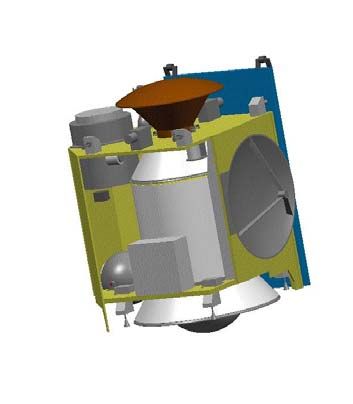
6.          MICRO-MARS VEHICLE DESIGN                    off-loading. The GNC subsystem uses an onboard
                                                         computer commonly with the data handling system
The Micro-Mars mission will be launched by               for guidance and control of the attitude. Attitude
Ariane-5 ASAP and has to fit into the adapter            measurement will be achieved by 2 star sensors, a
envelope during launch (figure 3). The primary           sun-sensor and an Inertial Measurement Unit (IMU).
structure of the orbiter, which also integrates the
micro lander, consists of a central tube with attached                         landing  device
                                                                                  Landegerät     ∅m0.7 m
                                                                                             ∅ 0,7
platforms for payload and subsystem units (figure 4).

                                                                        5,5m
                                                                      5.5  m

                                                         Figure 5: Micro-Mars flight configuration
Magnetometer
with Boom                                                The necessary electrical power will be provided by
                                                         2 deployable solar arrays in combination with a NiH2
                                                         battery system and a power control unit. After
                                                         unfolding, the Micro-Mars spacecraft will have a
Figure 3: Orbiter and lander in launch configuration     dimension     of    5.5    m    (figure   5).    The
                                                         telemetry/telecommand system will collect the
                                  S-Band Antenna
     Mars Camera
                    Lander                               housekeeping and payload data and will distribute
                                 Star sensor 1
                                                         the received telecommands to the subsystems
                                                         controlled by the onboard computer. This TTC
                                                         system is connected with the communication
                                       X-Band            system, which transmits the data via its X-Band
                                       Antenna
                                                         downlink to the receiving station on earth
                                       10 N Thruster
                                                         (Weilheim/Germany). A one meter reflector antenna
                                                         as high gain antenna allows a 1 kbit/s data rate.
       Star                                              Telecommand will be transmitted from earth via an
     Sensor 2
                                                         S-Band communication system.
                                         Central Tube
                                          With Tanks     Thermal control will be provided by a simple passive
                                                         system with some additional heaters controlled by
         Battery System
                                  22 N Thrusters         thermostats. Table 3 shows the mass budget of the
                                                         Micro-Mars spacecraft and figure 6 depicts the
                                                         system dimensions.

Figure 4: Inside view of the orbiter

The orbiter is equipped with a bi-propellant
propulsion system, consisting of two large tanks
inside the central tube, four 22 N thrusters for the
orbit maneuvers and four additional 10 N thrusters
allowing in combination with the 22 N thrusters a
three axes attitude torque capability as back-up for
the reaction wheels as well as for the wheels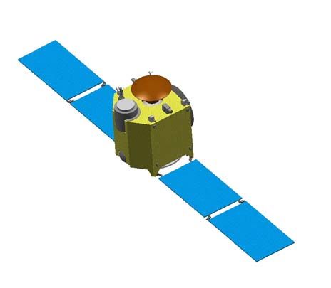
Payload incl. Lander                      30          will reduce the descend velocity to about 20 m/s. In
     Propulsion S/S                            36          the last phase until touch-down, the lander is
     Communication S/C                       11.5          equipped with an airbag-system to reduce the
     GNC S/S                                  6.5          landing shock for the surface station with a mass of
     Power Supply                            16.0          about 4.2 kg of subsystem avionics and scientific
     Data Handling S/S                        4.0          payload instrumentation. The total mass of the
     Structure S/S                           40.0          lander is about 15 kg.
     Thermal Control S/S                      7.8
     Bi-Propellant                          205.0
     Margin                                   3.2

     Launch Mass                         360.0 kg

Table 3: Micro-Mars system mass budget

                                                           Figure 7: Micro-Mars lander in 3-D view

                                                           Figure 8: Micro-Mars lander with its dimension

                                                           Figure 7 shows the Micro-Mars lander in a 3-D view
                                                           and figure 8 gives the main dimensions of the
Figure 6: Lander and orbiter with their dimensions         lander. The deployed surface station with the lander
                                                           payload accommodation is shown in figure 9. The
7.      MICRO-MARS LANDER DESIGN                           different phases for descent and landing are
                                                           schematically shown in figure 10.
The Micro-Mars lander will be a ballistic capsule
system, transported to the Mars orbit by the orbiter,      A number of different lander experiments were
which will also perform the de-orbit maneuver,             investigated covering the fields of environmental
release the capsule and return into the original orbit.    measurements, and geochemical measurements.
The lander will descend on a ballistic flight trajectory   Major constraints for selecting the baseline payload
with an entry angle of about -12 degrees and a velo-       were low mass, low power consumption, and
city of about 5,000 m/s.                                   requirements with respect to mobility and system
                                                           complexity. By taking into account the scientific
The capsule will land in the equatorial region within      advantage     of    complementary      simultaneous
± 25° latitudes using a heatshield for the                 measurements on ground and in orbit, a strawman
atmospheric deceleration with a maximum of -8 g            payload was selected which concentrates on
and a maximum heat flow of about 180 kW/m2.                measurements of the Martian environment and
Subsequently, a parachute with a surface of 50 m2          comprises the following instruments:
• A magnetometer including an inclinometer to In order to cope with the available power, instrument
measure in parallel the properties of the operations on the lander will be phased in time.
magnetic field in orbit and on ground
• A dosimeter experiment measuring the dose
rates of ionized radiation as well as the intensity
and timely variations of the UV radiation on
ground in addition to similar measurements in
orbit
• A radiometer to measure remotely timely
variations in temperature and to derive the
physical properties of the surface
• A suite of atmospheric sensors to determine
pressure, wind velocity and direction, and other
parameters
• A camera equipped with an APS CMOS detector
to determine the landing site position, to provide
the context information of the surroundings, and
to perform atmospheric measurements.
Experiment Mass [g] Power [W]
Dosimeter 150 0.30
Magnetometer 190 0.40
Radiometer 100 0.15
Atmospheric sensors 460 0.20
Camera 100 1.00
Lander payload total 1000 2.05
Table 4: Lander experiments mass and power
budgets
A summary of the lander payload mass and power
budgets is given in table 4. Many of the experiments Figure 9: Micro-Mars surface station
are mounted on a boom (figure 9).
References for EDL calculations:
- Atmospheric model of Mars: Mars-GRAM 2001
- Software: Fortran code (Babakin Space Center)
Atmospheric entry
h=120km
Main parachute v=5,000m/s
activation (16m²) Initial spin=0.5rpm
h=14km, v=300m/s Entry angle=-11°
Front shield separation
Start of surface module hanging
Start of air bags inflation
h=13.1km, v=74m/s
End of surface module hanging
End of air bags inflation (∅ 0.8m)
Martian station starts operation after
verticalization
Landing / Touchdown
Parachute and fall-line separation
Figure 10: Micro-Mars lander descent and landing phases8. SUMMARY The Micro-Mars mission project has finished the phase A study and will start its phase B hopefully at the beginning of 2004 to meet the launch window in 2007 for an Ariane-5 piggyback launch into GTO. The injection window to Mars will be in September 2007 leading to an arrival at Mars in July-August 2008. The study did show, that a low-cost mission with a total mass of 360 kg including fuel is capable to transfer and operate a scientifically demanding payload in orbit around Mars as well as to place a small lander on the Martian surface. If this low-cost micro mission will be successful, the micro mission spacecraft has the capability to provide the S/C bus for further planetary missions, needing only minor modifications. 9. ACKNOWLEDGEMENTS Babakin Space Center, Moscow carried out the lander design described in this paper [2] and also contributed to a preliminary orbiter configuration under a contract with EADS-ST GmbH Bremen. 10. REFERENCES 1. G. Neukum, H. Hoffmann, L. Kerstein, B. Bischof: Kleinsatellitenmission µMars, pp. 30, 2000 2. Babakin Space Center, Moscow: Micro-Mars Mission, draft scientific - technical report, 2002
You can also read