NHD-12864AZ-NSW-BBW-TR - ROHS
←
→
Page content transcription
If your browser does not render page correctly, please read the page content below
Product Specification

NHD-12864AZ-NSW-BBW-TR

Newhaven Display International, Inc.
2661 Galvin Court, Elgin, IL 60124 USA
                                         REACH       RoHS
Ph: 847.844.8795 | Fx: 847.844.8796      Compliant   Compliant
www.newhavendisplay.com
Table of Contents
Document Revision History .......................................................................................................................... 2
Mechanical Drawing .................................................................................................................................... 3
Pin Description ............................................................................................................................................ 4
Wiring Diagram ........................................................................................................................................... 4
Electrical Characteristics .............................................................................................................................. 5
Optical Characteristics ................................................................................................................................. 5
Controller Information................................................................................................................................. 5
Table of Commands ..................................................................................................................................... 6
Timing Characteristics .................................................................................................................................. 7
Example Initialization Program .................................................................................................................... 8
Quality Information ..................................................................................................................................... 9
Additional Resources
➢ Support Forum: https://support.newhavendisplay.com/hc/en-us/community/topics
➢ GitHub: https://github.com/newhavendisplay
➢ Example Code: https://support.newhavendisplay.com/hc/en-us/categories/4409527834135-Example-Code/
➢ Knowledge Center: https://www.newhavendisplay.com/knowledge_center.html
➢ Quality Center: https://www.newhavendisplay.com/quality_center.html
➢ Precautions for using LCDs/LCMs: https://www.newhavendisplay.com/specs/precautions.pdf
➢ Warranty / Terms & Conditions: https://www.newhavendisplay.com/terms.html
1Document Revision History
Revision Date Description Changed By
0 11/15/2008 Initial Release -
1 08/25/2009 User Guide Reformat BE
2 03/24/2010 Mechanical Drawing/Pin Description Updated BE
3 05/20/2010 Updated Pin Description and Electrical Characteristics MC
4 12/14/2012 Controller Information Updated AK
5 04/17/2013 Temperature Compensation Circuit Information Removed AK
6 10/25/2016 Electrical & Optical Characteristics Updated SB
7 10/19/2018 Driver IC, Backlight Current, & Mechanical Drawing Updated SB
8 05/20/2020 Updated Supply Current for Display & Backlight & Logic Voltages AS
Part Revision Updated to Rev1A
9 05/27/2021 Updated Supply Current and Mechanical Drawing JT
10 11/18/2021 Updated Mechanical Drawing ZP
11 01/26/2023 Document Format Updated KL
21 2 3 4 5 6 7 8
Mechanical Drawing
A A
B B
128x64 DOTS
C C
PO-WWYY
NHD-12864AZ-NSW-BBW-TR_Rev1A
NEWHAVEN DISPLAY
20 1
PIN ASSIGNMENT
1 VSS
D 2 VDD D
3 V0
4 RS
5 R/W
6 E
7~14 DB0~DB7
15 CS1
16 CS2
17 RST
E 18 VEE E
19 LED+
Product Descrip�on: 128x64 Graphic LCD 20 LED-
1. Driver IC: AiP31108U
2. Driving Mode: 1/64 Duty, 1/9 Bias Standard Tolerance:
(Unless otherwise specified)
3. Interface: 8-Bit Parallel Linear: ±0.3mm
Drawing/Part Number:
NHD-12864AZ-NSW-BBW-TR
Revision:
1A
4. Power Requirement: 5.0V Unless otherwise specified:
• Dimensions are in Millimeters
Drawn By:
K. Lewis
Approved By:
K. Lewis
F 5. Op�cal Features: STN (-) Blue, Transmissive, 6:00 View, White Backlight • Third Angle Projection
Drawn Date:
01/26/2023
Approved Date:
01/26/2023
F
6. Recommended Pin Header: 1x20pin 2.54mm pitch This drawing is solely the property of Newhaven Display International, Inc.
The information it contains is not to be disclosed, reproduced or copied in
whole or part without written approval from Newhaven Display.
1 2 3 4 5 6 7 8Pin Description
Pin No. Symbol External Connection Function Description
1 VSS Power Supply Ground
2 VDD Power Supply Supply Voltage for Logic (+5.0V)
3 V0 Adj. Power Supply Supply Voltage for contrast (approx. -4.5V)
4 RS MPU Register Select: 1=Data, 0=Instruction
5 R/W MPU Read/Write select signal, R/W=1: Read R/W: =0: Write
6 E MPU Operation Enable signal. Falling edge triggered.
7-14 DB0-DB7 MPU This is an 8-bit-directional data bus
15 CS1 MPU Chip Selection: CS1=H, CS2=L → select IC1 (left side)
16 CS2 MPU CS1=L, CS2=H → select IC2 (right side)
17 /RST MPU Active LOW Reset signal
18 VEE Power Supply Negative voltage output (-5.0V)
19 LED+ Power Supply Backlight Anode (+5.0V via on-board resistor)
20 LED- Power Supply Backlight Cathode (Ground)
Recommended LCD connector: 2.54mm pitch pins
Backlight connector: on LCD connector
Wiring Diagram
4Electrical Characteristics
Item Symbol Condition Min. Typ. Max. Unit
Operating Temperature Range TOP Absolute Max -20 - +70 ⁰C
Storage Temperature Range TST Absolute Max -30 - +80 ⁰C
Supply Voltage VDD - 4.8 5.0 5.2 V
Supply Current IDD VDD = 5.0V 1.0 2.5 4.5 mA
Supply for LCD (contrast) VLCD TOP = 25°C 9.3 9.5 9.7 V
“H” Level input VIH - 2.2 - VDD V
“L” Level input VIL - VSS - 0.6 V
“H” Level output VOH - 2.4 - VDD V
“L” Level output VOL - VSS - 0.4 V
Backlight Supply Voltage VLED - 4.8 5.0 5.2 V
Backlight Supply Current ILED VLED = 5.0V 20 40 60 mA
*The LED of the backlight is driven by current drain; drive voltage is for reference only. Drive voltage must be selected to ensure backlight current drain is below MAX
level stated.
Optical Characteristics
Item Symbol Condition Min. Typ. Max. Unit
Top ϕY+ 30 40 - ⁰
Optimal
Bottom ϕY- 50 60 - ⁰
Viewing CR ≥ 2
Left θX- 50 60 - ⁰
Angles
Right θX+ 50 60 - ⁰
Contrast Ratio CR - 2 5 - -
Rise TR - 150 250 ms
Response Time TOP = 25°C
Fall TF - 200 300 ms
Controller Information
Built-in AiP31108U controller: https://support.newhavendisplay.com/hc/en-us/articles/4414490987415-AiP31108
5Table of Commands
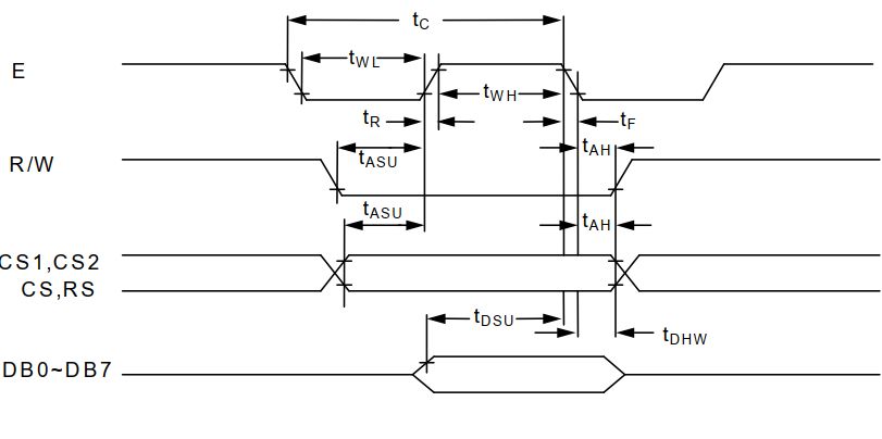
6Timing Characteristics
7Example Initialization Program
Sub Init
Reset P3.2
Set P3.2
Reset P3.4
Reset P3.0
Reset P3.7
Reset P3.6
Reset P3.1
A = &H3F
Call Comleft 'display on
Call Comright 'display on
End Sub
'-------------------------------------------------------------------------------
Sub Comleft
P1 = A
Set P3.6
Reset P3.0
Set P3.4
Reset P3.4
Reset P3.6
End Sub
Sub Comright
P1 = A
Set P3.1
Reset P3.0
Set P3.4
Reset P3.4
Reset P3.1
End Sub
Sub Writeleft
P1 = A
Set P3.6
Set P3.0
Set P3.4
Reset P3.4
Reset P3.6
End Sub
Sub Writeright
P1 = A
Set P3.1
Set P3.0
Set P3.4
Reset P3.4
Reset P3.1
End Sub
8Quality Information
Test Item Content of Test Test Condition Note
High Temperature storage Endurance test applying the high storage +80⁰C , 48hrs 2
temperature for a long time.
Low Temperature storage Endurance test applying the low storage -30⁰C , 48hrs 1,2
temperature for a long time.
High Temperature Endurance test applying the electric stress +70⁰C , 48hrs 2
Operation (voltage & current) and the high thermal
stress for a long time.
Low Temperature Endurance test applying the electric stress -20⁰C , 48hrs 1,2
Operation (voltage & current) and the low thermal
stress for a long time.
High Temperature / Endurance test applying the electric stress +40⁰C , 90% RH , 48hrs 1,2
Humidity Operation (voltage & current) and the high thermal
with high humidity stress for a long time.
Thermal Shock resistance Endurance test applying the electric stress 0⁰C,30min -> 25⁰C,5min ->
(voltage & current) during a cycle of low 50⁰C,30min
and high thermal stress. = 1 cycle, for 10 cycles
Vibration test Endurance test applying vibration to 10-55Hz , 15mm amplitude. 3
simulate transportation and use. 60 sec in each of 3 directions
X,Y,Z
For 15 minutes
Static electricity test Endurance test applying electric static VS=800V, RS=1.5kΩ, CS=100pF
discharge. One time
Note 1: No condensation to be observed.
Note 2: Conducted after 4 hours of storage at 25⁰C, 0%RH.
Note 3: Test performed on product itself, not inside a container.
9You can also read