OFFSHORE RACING CONGRESS - ORC Grand Prix 33 Class Rules 2021 - ORC.org
←
→
Page content transcription
If your browser does not render page correctly, please read the page content below
World Leader in Rating Technology

OFFSHORE RACING CONGRESS

                   ORC Grand Prix 33
                    Class Rules 2021
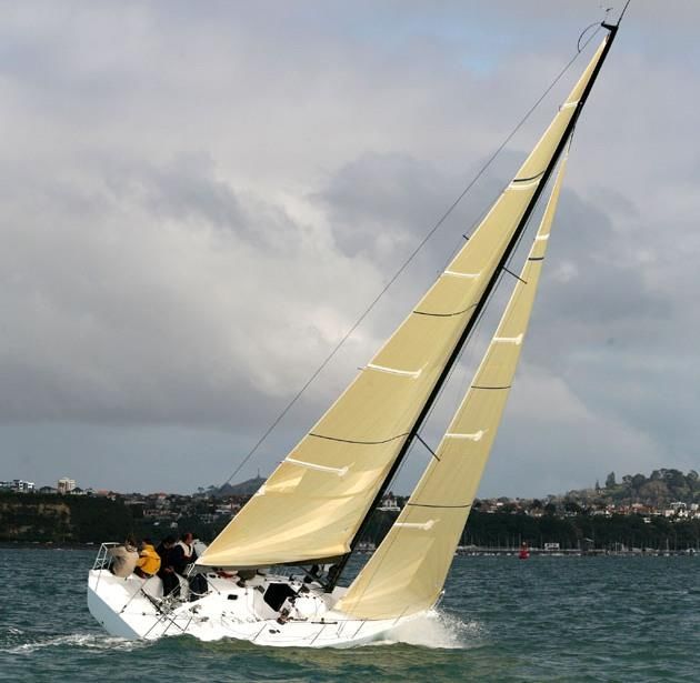
Copyright © 2021 Offshore Racing Congress.

All rights reserved. Reproduction in whole or in part is
only with the permission of the Offshore Racing Congress.

Cover picture by courtesy Ivor Wilkins
Part 1 - ADMINISTRATION

100     Rule Philosophy
        It is the intention that the rules and specifications for the ORC Grand Prix Classes provide close racing
        without time allowance in grand prix competition and that the yachts designed to this rule be fast,
        sound and seaworthy, retaining thereby, with a minimum of modification, good value beyond their
        competitive life as grand prix racers.

101     Authorities
        The sole authority for the GP 33 Class is the Offshore Racing Congress and it shall be maintained and
        administered at the ORC's discretion.

102     Administrative
102.1   The official language of the ORC GP Class Rules is English and in case of dispute over translations
        the English text shall prevail.
102.2   The word "shall" is mandatory and the word "may" is permissive.
102.3 Except where used in headings, when a term is printed in “bold” the definition in the ERS applies and
      when a term is printed in “italics” the definition in the RRS applies.
102.4 When printed in "bold italics" the term is used as measurement taken or recorded by the measurer.

103     Abbreviations and Definitions
        ERS     Equipment Rules of Sailing
        GP      Grand Prix
        IMS     International Measurement System
        ISAF    International Sailing Federation
        ORC     Offshore Racing Congress
        OSR     Offshore Special Regulations
        RRS     Racing Rules of Sailing

104     ISAF and ORC Rules
104.1 RRS, IMS and ERS shall apply except when changed by these class rules.
104.2   ISAF Advertising Code shall apply.
104.3   ISAF OSR Category 3 shall apply.

105     Rules Amendments
        Amendments to the GP 33 Class Rules are subject to the submission by the ORC Nominating bodies
        or GP 33 Class Association and approval of the ORC in accordance with the Articles of Association
        of ORC Ltd. GP 33 Class Association shall give its opinion about any submission concerning GP 33
        Class Rules and ORC will be bounded by that opinion before making final decision.

106     Rules Interpretations
        The Class Technical Committee with approval of the ORC Chief Measurer may at any time issue
        interpretations or correction of the GP class rules. Any such interpretation or correction shall be
        published and then deemed final unless and until overruled by the ORC Management Committee and
        Congress.
Part 2 - ELIGIBILITY
201 Hull
201.1 Permitted materials. In the construction of the hull and deck structures and in interior panels, except
for hardware, fastenings and keel support structures, only the following materials are permitted: E-
glass, Carbon, Kevlar, Epoxy, Vinylester and Polyester resin, Foam Core with minimum density of 75
kg/m3, Balsa Core, Plywood.
a) Stainless steel and aluminium are permitted for keel support structures inside the hull shell.
b) Titanium is not permitted in any purpose. Carbon is not permitted in winches or winch systems
except if standard, unmodified production winches usually supplied are used.
c) The modulus of the carbon used in the rudder is limited to 250 GPa.
201.2 Construction Scantlings. The boats shall have been designed and built either in accordance with the
ABS Guide for Building and Classing Offshore Yachts or, when ultimately published, in accordance
with ISO Standard 12215. The designer and the builder, respectively, shall confirm by signed written
declarations that the design and build comply. The Owner shall sign the declaration printed on the
measurement certificate.
201.3 Hollows in Hull. Aft of 30% LOA the hull there shall be no hollows in the hull surface below the
sheerline. The sheerline shall be a fair, concave curve in profile view and a fair, convex curve in plan
view with no double inflections in either view. Hollows generated by any protrusion outside the outer
skin of the hull are not allowed. A recess, of a maximum of 20 litres of volume, is permitted in the
hull, only in the area of the keel attachment and for this purpose only. The keel (when in position)
shall totally fill this recess. Any part of the keel contained in this recess, as well as outside the hull
outer skin, is considered keel and will be weighed as keel.
201.4 Working Deck. The working deck shall have a positive camber (i.e., convex) and be continuously
fair. Except for the coach roof an the cockpit, at any transverse section the deck camber, as measured
from a horizontal datum passing through the sheer points, shall be not less than 2%. Trunks and troughs
are not permitted. Fittings may be recessed, provided the recess dimensions are not larger than 120%
of the fitting dimension.
202 Appendages
202.1 Except for a single rudder located aft of the keel, no other moveable appendages are permitted.
202.2 Except for fairing (no more than 10 mm thick), no material other than lead, antimony, steel or iron are
permitted in the structure of the keel blade, fin and in any bulb.
202.3 Hollows between the sections at KTHU and KTHL are not permitted.
203 Propulsion Engine and Strut Drive
203.1 A securely covered inboard propulsion engine as water cooled diesel of minimum 14 HP shall be
provided together with permanently installed exhaust and fuel supply systems and fuel tank(s). The
engine and drive train shall be orientated for and aft, located on the centerline of the boat.
203.2 Retractable propellers as well as retractable or custom strut drives are not allowed. Only standard,
unmodified production strut drives usually supplied with the following engines are allowed: Volvo
Penta, Yanmar, Lombardini Marine.
204 Rig
204.1 Throughout its length, the mast shall be fair with no hollows and be of continuous section from the
butt to the upper measurement point of IG.
204.2 Where carbon fiber is incorporated in the construction of any spars on the yacht, this shall be limited
to 250 GPa and the walls of the spar shall not be of cored construction.
204.3 There shall be two spreader sets. The sweep-back angle of spreaders shall be not less than 15 degrees.
Curved spreaders are not permitted.204.4 Jumper struts and stays, outriggers and halyard locks are not permitted.
204.5 Spinnaker pole is not permitted and any headsail flown shall at all times be tacked at the centerline of
the yacht. The bowsprit shall be capable of being retracted so that its forward end is not longer than
200 mm forward of the stem. When bowsprit is extended the boat shall be in the process of a
continuous hoist, or flaying or dropping the spinnaker. The bowsprit shall also be retracted at the first
reasonable opportunity after rounding the leeward mark. Approaching a windward mark without the
spinnaker set, the bowsprit shall not be extended until the bow of the boat has passed the mark.
204.6 Standing Rigging. Except for the permanent backstay, all standing rigging shall be of stainless steel
rod or twisted stainless steel wire and subject to the limitations set forth below. Titanium is not
permitted in any purpose.
a) Backstay. Backstays are limited to a single, permanent backstay, which may be of stainless steel
or composite fiber construction. The backstay may be adjustable. From the upper attachment
point of the backstay there shall be a single part only, of length not less than “P”, the intention
being to prohibit any configuration which might simulate double backstays. Below the lower end
of this single part, the backstay configuration is unrestricted except that the fixed anchor point of
the backstay configuration shall be not higher than 200mm above the working deck.
A “fixed anchor point” is any point where a block or the end of any rope used to tune the backstay
is attached. When in tension, the backstay shall form a straight line between the top (mast crane)
and bottom fixed anchor attachment points. The centre of any bottom fixed anchor point shall not
be above a horizontal plane which is established 0.72 m from the waterline in measurement trim.
Pre bent backstays and/or any system to artificially increase the distance between the straight
backstay line and the mainsail roach is not allowed, except for soft battens “flippers”.
b) Forestay. Except for backstay adjustment, means for adjusting forestay tension while racing is
not permitted. Any luff-groove device shall not incorporate carbon fibers in construction.
205 Sails
205.1 Maximum of five battens are permitted in the mainsail, and no battens are permitted above MGT point.
205.2 Asymmetric spinnaker luff shall be calculated as: ASL = 0.5 * SLU + 0.5 * SLE
205.3 Exclusive of storm sails required by the Offshore Special Regulations, sails allowed on board while
racing are limited to:
1 Mainsail
2 Headsails
3 Asymmetric spinnakers
205.4 In addition to the standard ORC stamp, all sails shall be stamped by official GP class measurement
stamp where sail number, date of measurement, name of measurer and type of sail with appropriate
identification per year will be recorded. First set of sails shall be measured in the same year when boat
is launched. Maximum number of sails measured in one calendar year (January 1st – December 31st)
for boat when participating to the official GP 33 Circuit is defined as follows:
2 Mainsail
5 Headsails
5 Asymmetric spinnakers
Damaged sails can be repaired, but than shall be re-measured and re-stamped with both ORC and GP
measurement stamp where same sail identification will be used.
206 Crew weight
The weight of all crew members on board while racing in light street clothes shall not be greater than
640 kg.Part 3 - MEASUREMENT
301 Measurement
301.1 All measurement shall be under the metric system.
301.2 All measurements shall be within the limits defined in these class rules without any rounding of
measured or calculated values (e.g. where a limit is given as maximum 12.5, a measured value of
12.501 would not comply.)
301.3 Measurement shall be carried out by an official measurer who shall complete the measurement form
and send it to the ORC.
302 Hull and appendages
Freeboard stations shall be defined as follows:
SFFP shall be taken as 0.200 m.
SAFP shall be normally taken as defined in IMS B2.2(c), but not forward of 12% LOA of the
aftermost point of the hull
Following measurements shall be taken following appropriate IMS rules:
LOA Length overall B6.2
MB Maximum Beam B6.3
DSPW Displacement as Weighed B6.11
FFM Freeboard Forward Measured B5.3
FDM Freeboard at Maximum Draft B6.7
FAM Freeboard Aft Meausred B5.4
SDM Station of Maximum Draft B6.5
DMT Deepest Point of Keel to Sheerline B6.6
EDL Strut Drive Length D4.8
Additional keel measurements shall be taken as follows:
KW shall be the weight of complete keel, including any bulb, excluding fasteners.
KTHU shall be the maximum thickness found at a horizontal section located 100 mm below the
intersection of the keel root and the hull surface.
KTHM shall be the maximum thickness found at a horizontal section located midway the sections at
KTHU and KTHL
KTHL shall be the maximum thickness found at a horizontal section located 100 mm above the
intersection of the keel blade and keel bulb.
KBW shall be the maximum transverse width of the keel bulb.
KBWT shall be the weight of the keel bulb.
303 Rig
Following measurements shall be taken following appropriate IMS rules:
P Mainsail Hoist F2.1
IG Height of Genoa Hoist F3.1
ISP Height of Spinnaker Hoist F3.2
BAS Boom Above Sheerline F3.4
MWT Mast Weight F8.1
MCG Mast Vertical Center of Gravity F8.2
MDT1 Max. Transverse Mast F4.1
MDL1 Max. Fore-and-Aft Mast F4.2
MDT2 Min. Transverse Mast F4.3
MDL2 Min. Fore-and-Aft Mast F4.4
TL Taper Length F4.5
GOA Backstay Gantry Overhang F4.8
CPW Chainplate Width F6.3
E Mainsail Foot F5.1BD Boom Diameter F5.2
J Foretriangle Base F6.1
TPS Tacking Point of Spinnaker F7.2
FSP Forestay Perpendicular F6.5
304 Sails
Following measurements shall be taken following appropriate IMS rules:
MHB Mainsail Top Width G2.1
MUW Mainsail 7/8 Width G2.1
MTW Mainsail 3/4 Width G2.1
MHW Mainsail 1/2 Width G2.1
MQW Mainsail 1/4 Width G2.1
HTW Headsail 3/4 Width G4.1
HHW Headsail 1/2 Width G4.1
HLP Headsail Perpendicular G4.1
SHW Asymmetric Spinnaker Mid Width G6.5
SLU Asymmetric Spinnaker Luff G6.5
SLE Asymmetric Spinnaker Leech G6.5
305 Internal ballast and batteries
Internal ballast, if any, shall not weight more than 9% of Max DSPW. Batteries shall not weight more
than 2% of Max DSPW. The weight and location of internal ballast and batteries shall be recorded on
the Measurement Inventory.
306 Maximum draft
The Maximum Draft of the yacht shall be calculated as DHKM = DMT – FMD.
307 Measurement Inspection
Following tolerances will be acceptable on the measurement inspection during an event:
DSPW +/- 20 kg
KW +/- 8 kg
FFM, FMD, FAM +/- 3 mm
308 Certificate
308.1 Upon receipt of a satisfactory completed measurement form and certification fee, the ORC will issue
a measurement certificate.
308.2 A boat shall have only one valid certificate at any one time. The valid certificate shall be only the last
issued. The certificate shall be valid until 31st December of the current year.
308.3 A certificate shall be changed upon the change of any measurement recorded in the certificate or
change of ownership.
308.4 A boat shall have no more than two valid certificates issued as a result of a change of recorded
measurement values in period from January 1st to December 31st each year.
308.5 ORC in agreement with the Class Technical Committee can withdraw any certificate in any time when
it finds that boat may not comply with intention of these class rules. In such a case it will inform the
owner about further actions and if needed, appoint the measurer to re-measure the boat.Part 4 - TABLE OF LIMITS
401 Limits
All measurements shall be within the limits defined in the following table:
Min. Max. Rule Descirption
Hull
LOA --- 9.990 IMS B6.2 Length Overall
MB 2.700 3.000 IMS B6.3 Maximum Beam
DSPW 2000 2150 IMS B6.11 Displacement as Weighed
DHKM --- 2.200 GP 306 Maximum Draft
EDL 0.530 --- IMS D4.8 Strut Drive Length
FFM 1.070 1.170 IMS B5.3 Freeboard Forward
FDM 0.920 1.020 IMS B6.7 Freeboard at Maximum Draft
FAM 0.820 0.920 IMS B5.4 Freeboard Aft
Keel
KW 950 1050 GP 302 Keel Weight
KTHU 0.075 --- GP 302 Keel Thickness – Upper
KTHM 0.069 --- GP 302 Keel Thickness – Mid
KTHL 0.063 --- GP 302 Keel Thickness – Lower
KBW --- 0.500 GP 302 Keel Bulb Transverse Width
Rig
P --- 12.800 IMS F2.1 Mainsail Hoist
IG --- 12.300 IMS F3.1 Height of Genoa Hoist
ISP --- 14.200 IMS F3.2 Height of Spinnaker Hoist
BAS 1.300 1.400 IMS F3.4 Boom Above Sheerline
MWT 90.0 --- IMS F8.1 Mast Weight
MCG 4.190 --- IMS F8.2 Mast Centre of Gravity
MDT1 0.090 --- IMS F4.1 Max. Transverse Mast
MDL1 0.135 0.200 IMS F4.2 Max. For-and-Aft Mast
MDT2 0.7*MDT1 --- IMS F4.3 Min. Transverse Mast
MDL2 0.7*MDL1 IMS F4.4 Min. For-and-Aft Mast
TL --- 1.900 IMS F4.5 Taper Length
GOA --- 0.450 IMS F4.8 Backstay Gantry Overhang
CPW 2.250 --- IMS F6.3 Chainplate Width
E --- 4.750 IMS F5.1 Mainsail Foot
BD --- 0.237 IMS F5.2 Boom Diameter
J --- 3.800 IMS F6.1 Foretriangle Base
TPS --- 6.000 IMS F7.2 Tacking Point of Spinnaker
FSP --- 0.054 IMS F6.5 Forestay Perpendicular
Sails
MHB --- 0.20 IMS G2.1 Mainsail Top Width
MUW --- 1.23 IMS G2.1 Mainsail 7/8 Width
MTW --- 2.10 IMS G2.1 Mainsail 3/4 Width
MHW --- 3.27 IMS G2.1 Mainsail 1/2 Width
MQW --- 4.14 IMS G2.1 Mainsail 1/4 Width
HLP --- 4.10 IMS G4.1 Headsail Perpendicular
HTW --- 1.10 IMS G4.1 Headsail 3/4 Width
HHW --- 2.15 IMS G4.1 Headsail 1/2 Width
SHW --- 10.90 IMS G6.5 Asymmetric Spinnaker Mid Girth
ASL --- 15.40 GP 205.2 Asymmetric Spinnaker Luff/LeechAppendix 1 - ACCOMMODATION REGULATIONS
A1 Introduction
The purpose of these regulations is to ensure that boats meet the minimum standards of
accommodation in order to provide for comfort of crews and stowage of gear, maintain long term
value and to prevent unrated performance advantage from stripping hulls for racing.
A2 Interior Volume shall comply with following requirements:
1. Lower Reference Datum. A level datum, parallel to the waterplane in measurement trim, shall be
established at a height of 0.079 m above the inside of the hull surface, projected if necessary, at the
deepest interior fairbody section which, for this purpose, shall not be found outside the 90% IH
overhead area (see A2.3 below). This level is independent of the actual height of the cabin sole.
2. Overhead Area at Full Interior Height: At a height 1.46 m above the level established in A2.1
there shall exist under the overhead a plane of length not less than 1.40 m and area not less than 0.6
m2, ignoring deck beams and deck stringers. The aft extent of this area at the centerline shall lie not
forward of a point located 5.5 m aft of the stem.
3. Overhead Area at 90% Interior Height: At a height 1.31 m above the level established in A2.1
there shall exist under the overhead a plane of length not less than 1.90 m and minimum area 1.9
m2. At this defined plane there shall exist a rectangular area for length of 1.50 m and width not less
than 1.00 m. Deck beams and deck stringers may be ignored.
All types of cut-outs and fitting recesses penetrating into the volume defined by 2 and 3 are forbidden.
Only control lines may pass into the coach-roof volume.
A3 A Cabin Sole shall extend fore and aft over a length which provides convenient access to lockers,
berths, galley, head, navigation area and other components making up the yacht’s interior.
A4 Berths. Minimum number of berths is 3. Each single berth of should be at least 1.9 m in length and at
some point at least 0.6 m in width. A double berth shall be at least twice the width of a single berth.
The ends of berths may taper as required by the hull shape. Mattresses are to be fitted to all such berths.
A5 Personal Gear Stowage shall be provided in the form of built-in lockers of minimum volume of
0.14 m3.A6 Galley Area:
1. Stoves: A gimbaled stove fitted with high retaining rails to permit safe operation underway.
2. Sinks: Permanently installed and fitted with pump/tap and drainage system.
3. Galley Gear Stowage: Should be provided in rigid lockers, bins or compartments.
4. Food Stowage: Stowage for food should be provided in rigid lockers, bins or compartments of
minimum volume of 0.22 m3.
A7 1. Toilet Marine type permanently installed and operable in compliance with local regulations.
2. Wash Basin: Near the toilet, fitted with pump/tap and drainage system which permits use
underway.
A8 Navigation Area shall include flat area suitable for chart work. The area should be built with storage
for charts, navigational instruments, books, etc.
A9 Hanging Locker(s) shall be of sufficient dimension to permit hanging garments vertically.
A10 Fresh Water Capacity: Fresh water pumps shall be installed at the sink and wash basin and fresh
water shall be contained in permanently installed tankage either of rigid construction or of the bladder
type. Minimum fresh water capacity is 50 litres.
A11 Fuel Capacity: Inboard engines shall be directly supplied from permanently installed fuel tankage.
Minimum diesel fuel capacity is 32 litres (48 litres for gasoline).You can also read