PRESENTED BY: DAVE FORNARO PRINCIPAL ENGINEER ARISTON TECHNOLOGIES, LLC
←
→
Page content transcription
If your browser does not render page correctly, please read the page content below
PRESENTED BY:
                                  DAVE FORNARO
                                PRINCIPAL ENGINEER
                            ARISTON TECHNOLOGIES, LLC
54 Julia Ct., Kingston, RI 02881 • 401-575-8144 • www.aristontech.com • info@aristontech.com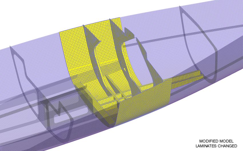
OUTLINE

       1. BASICS OF FINITE ELEMENT ANALYSIS (FEA)

       2. FEA COMPARED TO FIRST PRINCIPLES

       3. FEA COMPARED TO SCANTLINGS

       4. ANATOMY OF A FINITE ELEMENT ANALYSIS

       5. TIPS & RECOMMENDATIONS

54 Julia Ct., Kingston, RI 02881 • 401-575-8144 • www.aristontech.com • info@aristontech.com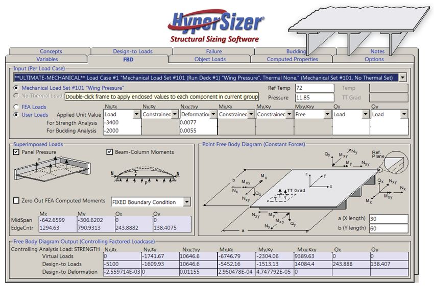
BASICS OF FINITE ELEMENT ANALYSIS (FEA)
Finite Element Analysis is an approximate method for studying continuous physical
systems, by which the system is broken down into discrete geometric elements
interconnected at node points. These finite elements and their interrelationships,
along with applied loads and boundary conditions, are represented by a set of
simultaneous partial differential equations which are solved using matrix algebra.
FEA is most useful for systems that are geometrically too complicated for closed-
form (textbook) solutions, but it is often benchmarked using systems with known
solutions (e.g. beam in bending, column in compression, pressure vessel, etc…)
FEA can be used to solve problems involving displacement, strain, stress, buckling,
vibration, temperature, fluid flow, electro-magnetism and more…
Solutions can be linear, non-linear, static, dynamic, etc…
Materials can be isotropic, orthotropic, elastic, plastic, hyperelastic, etc…
Mesh density highly influences accuracy of results; A quality mesh is essential
54 Julia Ct., Kingston, RI 02881 • 401-575-8144 • www.aristontech.com • info@aristontech.com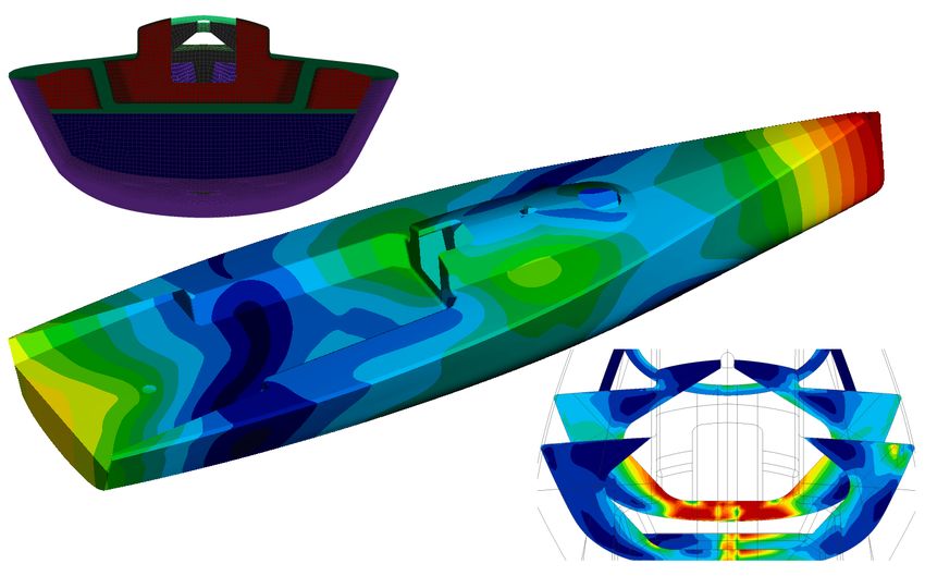
BASICS OF FINITE ELEMENT ANALYSIS (FEA), ctd…
Linear Analysis:
- Materials have a linear stress-strain relationship (e.g. metals below yield)
- Deflections are small and vary linearly with applied loads
Non-Linear Analysis:
- Materials may have a non-linear stress-strain relationship (e.g. metals beyond yield)
- Deflections may be large and not always be proportional to the applied loads
Static Analysis:
- Loads and boundary conditions do not vary with time
- Can also be a “snapshot” – i.e. quasi-static approximation of a dynamic system
Dynamic Analysis:
- Loads and boundary conditions may vary with time
- FE solution is an iterative (step-by-step) approximation of a continuous event
54 Julia Ct., Kingston, RI 02881 • 401-575-8144 • www.aristontech.com • info@aristontech.com
BASICS OF FINITE ELEMENT ANALYSIS (FEA), ctd…
Isotropic Materials:
- Properties are the same in all directions
- Defined by two elastic constants – Young’s Modulus (E) and Poisson’s Ratio (n)
Anisotropic Materials:
- Properties may vary in all directions
- Defined by 21 elastic constants
3D Orthotropic Materials:
- Two orthogonal planes of symmetry with different properties in each
- Defined by 9 elastic constants (E1, E2, E3, G12, G13, G23, n12, n13, n23)
- Applicable to solid composite materials
2D Orthotropic Materials:
- Orthotropic in one plane only, with constant properties normal to that plane
- Defined by 6 elastic constants (E1, E2, G12, G13, G23, n12)
- Applicable to planar composite materials
54 Julia Ct., Kingston, RI 02881 • 401-575-8144 • www.aristontech.com • info@aristontech.com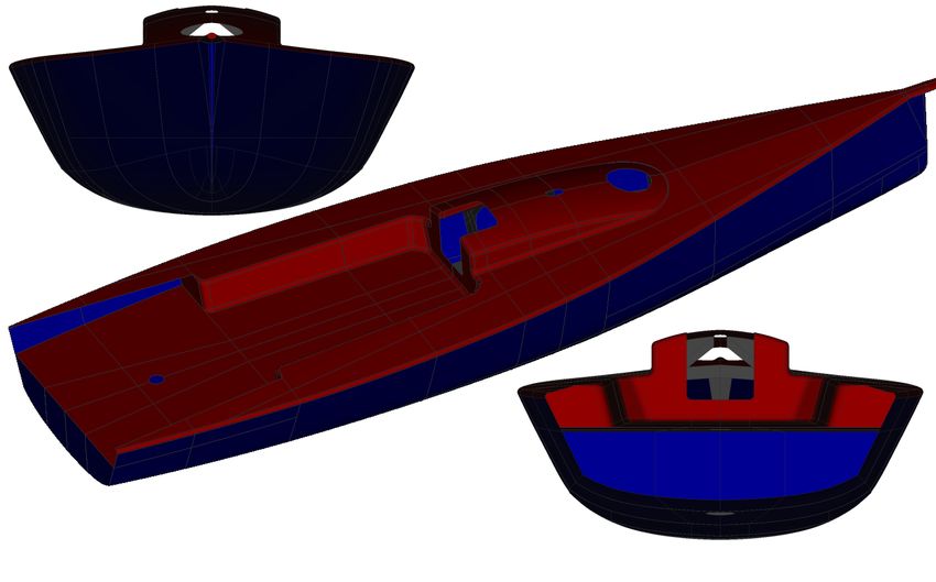
BASICS OF FINITE ELEMENT ANALYSIS (FEA), ctd…
Majority of yacht design-related composites FEA applications will be linear static
analyses using 2D orthotropic properties for laminates (shell elements)
Non-linear and dynamic analyses are useful for specialized studies (e.g. slamming),
although linear “quasi-static” simplifications are often made
Isotropic properties are generally used for foam core (shell or solid elements)
3D orthotropic properties can be used when through-thickness stresses of
orthotropic materials are required (e.g. honeycomb core modeled as solid
elements)
54 Julia Ct., Kingston, RI 02881 • 401-575-8144 • www.aristontech.com • info@aristontech.comFEA COMPARED TO FIRST PRINCIPLES
First principles (textbook) analysis methods for simple systems can often be used to
estimate the response of more complicated systems (e.g. hull in bending modeled
as a beam with variable cross-section and inertia properties)
First principles methods are commonly used to assess hull scantlings for cargo ships
subject to self-weight, cargo weight and buoyancy forces. Calculations are made
for shear forces and bending moments, which are used as inputs to scantling rules
Buoyancy force per unit length, FB = ρga
Weight force per unit length, FW = mg
Net vertical applied force, F = FB – FW = ρga – mg
Shear Force, Q = ∫Fdx = ∫(ρga – mg)dx
Bending Moment, M = ∫Q = ∫∫Fdx = ∫∫(ρga – mg)dxdx
54 Julia Ct., Kingston, RI 02881 • 401-575-8144 • www.aristontech.com • info@aristontech.comFEA COMPARED TO FIRST PRINCIPLES, ctd…
Simplified first-principles global hull strength assessment – load distributions (left), shear force and bending moment curves (right)
54 Julia Ct., Kingston, RI 02881 • 401-575-8144 • www.aristontech.com • info@aristontech.comFEA COMPARED TO FIRST PRINCIPLES, ctd…
Note that while this approach is first principles-based, it is not a simple hand calc!
While it could be programmed in Excel, this type of analysis is usually carried out
using dedicated software such as GHS, DELFTship or HST
Given the bending moment and shear force, a nominal bending stress at the
extreme fiber distance can be calculated according to σ = Mc/I and a nominal shear
stress calculated according to τ = Q/A
This would at best be a very rudimentary estimate of global bending stress, and will
not address local loads, sectional shape changes, stress concentrations, etc…
This can be useful for simple cases, but what if you had this…
54 Julia Ct., Kingston, RI 02881 • 401-575-8144 • www.aristontech.com • info@aristontech.comFEA COMPARED TO FIRST PRINCIPLES, ctd…
Load case for upwind sailing – global stress and deflection indeterminate, can’t be accurately assessed by first principles
54 Julia Ct., Kingston, RI 02881 • 401-575-8144 • www.aristontech.com • info@aristontech.comFEA COMPARED TO FIRST PRINCIPLES, ctd…
First principles calculations can be useful for providing basic information regarding
overall sectional shape and strength requirements for simple geometries and
loading conditions, either by direct (though approximate) assessment of stress and
deflection, or as required input to a scantling rule
First principles calculations can also be very useful for analyzing local strength of
panels, beams, fittings, attachments, etc… although assumptions must be made
regarding loading and boundary conditions that compromise accuracy
Many useful first principles-based composites laminate, panel and beam analysis
software are available including CoDA, ESAComp, HyperSizer, CompositePro, etc…
FEA by comparison has the potential to provide close to exact solutions for global
deflection and stress given a quality model
FEA can also provide detailed deflection and stress results for local features such as
bulkheads, frames, stringers, panels, fittings and attachments… but only if these
features are modeled in sufficient detail
54 Julia Ct., Kingston, RI 02881 • 401-575-8144 • www.aristontech.com • info@aristontech.comFEA COMPARED TO FIRST PRINCIPLES, ctd…
Typical first-principles / classical laminate theory-based software for ply, laminate, beam and panel analysis
54 Julia Ct., Kingston, RI 02881 • 401-575-8144 • www.aristontech.com • info@aristontech.comFEA COMPARED TO SCANTLINGS
Scantling rules are generally a combination of first principles calculations and
databases of empirical knowledge which have been used to develop acceptable
design practices for yachts falling into various categories – e.g. sailing yachts, power
yachts, high-speed craft, naval craft, cargo ships, barges, etc…
As discussed above, first principles calculations for global shear forces and bending
moments from hydrostatics programs are often used as inputs to scantling rules.
This is particularly true for rules governing cargo ships, less true for those governing
recreational craft
Scantling rules typically include first principles/empirical calculations for:
- Hull panel pressures based on location & other factors (e.g. dynamics)
- Bulkhead pressures based on location & other factors (e.g. collision, watertight)
- Required skin thicknesses, section modulii and moments of inertia based on
panel pressure and stiffener spacing, material properties, core thickness, etc…
- Required core thickness based on type and shear strength requirements
- Required stiffener spacing, depth, section modulus & moment of inertia
54 Julia Ct., Kingston, RI 02881 • 401-575-8144 • www.aristontech.com • info@aristontech.comFEA COMPARED TO SCANTLINGS, ctd…
Scantling rules generally do not provide detailed global or local stresses, although
the calculations for section modulus and moment of inertia are often based on
approximated first principles calculations for stress and stiffness
Scantling rule calculations for panels and beams include similar simplifications and
assumptions regarding loading and boundary conditions as for first principles-
based software
A good scantling rule will get you in the ballpark, and may provide the means for
some degree of basic optimization (e.g. materials, stiffener spacing, core thickness,
etc…) but is not an effective tool for detailed optimization of strength or stiffness
FEA by comparison offers much more detailed understanding of the response of
the structure to the applied loads, and far more complete capabilities for studying
changes to materials and layout in order to optimize the design
54 Julia Ct., Kingston, RI 02881 • 401-575-8144 • www.aristontech.com • info@aristontech.comANATOMY OF A FINITE ELEMENT ANALYSIS
FEA process illustrated using a model of a 42-foot racing yacht
Design by Mick Price at Weaver-Price Design & Engineering; Structural engineering
& optimization by Dave Fornaro at Ariston Technologies
Hull modeled in FASTSHIP; Deck & internal structure modeled in PRO/ENGINEER;
Pre- & Post-Processing done with FEMAP; Solutions run using NEi/NASTRAN
Major steps in the process detailed on the following slides:
- GEOMETRY
- MESH
- MATERIAL PROPERTIES
- LOADS & CONSTRAINTS
- SOLUTION & RESULTS
- OPTIMIZATION
54 Julia Ct., Kingston, RI 02881 • 401-575-8144 • www.aristontech.com • info@aristontech.comANATOMY OF A FINITE ELEMENT ANALYSIS – GEOMETRY
3D model of geometry to be analyzed is required
Surface models preferred over solid models
Quality surface models avoid lengthy editing or re-work prior to meshing
Hull & deck modeled at molded (usually outer) surfaces
Internal frames and stringers modeled at centerline surfaces
All surfaces split at intersections with other surfaces and at laminate zone extents
All surfaces must have consistent normal vectors for defining laminate thickness
direction (normal vectors ideally defined on surfaces prior to meshing and inherited
by elements during the meshing process)
54 Julia Ct., Kingston, RI 02881 • 401-575-8144 • www.aristontech.com • info@aristontech.comANATOMY OF A FINITE ELEMENT ANALYSIS – GEOMETRY
Geometry (surface) model – hull and deck shell
54 Julia Ct., Kingston, RI 02881 • 401-575-8144 • www.aristontech.com • info@aristontech.comANATOMY OF A FINITE ELEMENT ANALYSIS – GEOMETRY
Geometry (surface) model – hull and deck shell
54 Julia Ct., Kingston, RI 02881 • 401-575-8144 • www.aristontech.com • info@aristontech.comANATOMY OF A FINITE ELEMENT ANALYSIS – GEOMETRY
Geometry (surface) model – internal structure
54 Julia Ct., Kingston, RI 02881 • 401-575-8144 • www.aristontech.com • info@aristontech.comANATOMY OF A FINITE ELEMENT ANALYSIS – MESH
Auto-meshing pre-processor typically utilized
All curves and surfaces seeded with mesh controls to produce a quality mesh
Quadrilateral (4-sided) shells preferred over triangular (3-sided) shells for accuracy
Mesh should be quad-dominant, but a few tris are unavoidable in transition areas
Mesh density should be sufficient to replicate geometric shapes with high fidelity
Mesh should be ordered and structured (look pretty)
Pre-processor mesh quality controls should be utilized to search for connectivity
problems(free edges ) as well as warped, skewed or otherwise badly formed
elements and any errors should be corrected
54 Julia Ct., Kingston, RI 02881 • 401-575-8144 • www.aristontech.com • info@aristontech.comANATOMY OF A FINITE ELEMENT ANALYSIS – MESH
Finite Element Mesh – hull and deck shell
54 Julia Ct., Kingston, RI 02881 • 401-575-8144 • www.aristontech.com • info@aristontech.comANATOMY OF A FINITE ELEMENT ANALYSIS – MESH
Finite Element Mesh – hull and deck shell
54 Julia Ct., Kingston, RI 02881 • 401-575-8144 • www.aristontech.com • info@aristontech.comANATOMY OF A FINITE ELEMENT ANALYSIS – MESH
Finite Element Mesh – hull and deck shell
54 Julia Ct., Kingston, RI 02881 • 401-575-8144 • www.aristontech.com • info@aristontech.comANATOMY OF A FINITE ELEMENT ANALYSIS – MESH
Finite Element Mesh – hull and deck shell
54 Julia Ct., Kingston, RI 02881 • 401-575-8144 • www.aristontech.com • info@aristontech.comANATOMY OF A FINITE ELEMENT ANALYSIS – MESH
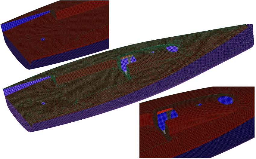
Finite Element Mesh – internal structure
54 Julia Ct., Kingston, RI 02881 • 401-575-8144 • www.aristontech.com • info@aristontech.comANATOMY OF A FINITE ELEMENT ANALYSIS – MESH
Finite Element Mesh – internal structure
54 Julia Ct., Kingston, RI 02881 • 401-575-8144 • www.aristontech.com • info@aristontech.comANATOMY OF A FINITE ELEMENT ANALYSIS – MESH
Finite Element Mesh – internal structure
54 Julia Ct., Kingston, RI 02881 • 401-575-8144 • www.aristontech.com • info@aristontech.comANATOMY OF A FINITE ELEMENT ANALYSIS – MATERIAL PROPERTIES
Individual plies modeled as 2D orthotropic materials defined by 6 elastic constants
required to run an analysis:
- E1 = Elastic Modulus in 1-fiber (parallel) direction
- E2= Elastic Modulus in 2-fiber (transverse) direction
- G12 = Shear modulus in 12-plane
- G13 = Through thickness modulus in 13-plane (often taken as resin modulus)
- G23 = Through thickness modulus in 23-plane (often taken as resin modulus)
- n12 = Poisson’s Ratio in 12-plane
Strength properties required only for failure index calculation:
- s1t = Tensile Strength in 1-fiber (parallel) direction
- s1c = Compressive Strength in 1-fiber (parallel) direction
- s2t = Tensile Strength in 2-fiber (transverse) direction
- s2c = Compressive Strength in 2-fiber (transverse) direction
- τ12 = Shear strength in 12-plane
54 Julia Ct., Kingston, RI 02881 • 401-575-8144 • www.aristontech.com • info@aristontech.comANATOMY OF A FINITE ELEMENT ANALYSIS – MATERIAL PROPERTIES
Ply data can be taken from vendor testing, in-house testing, standards; Can be
difficult to get good data (esp. for shear) – estimates sometimes have to be made
All elements must have normal direction defined, relative to which laminate stack
thickness is developed
All elements must have material angle defined, relative to which fiber directions are
oriented (methods include vector projection, draping)
Pre-processor quality control tools such as vector displays and backface shading
should be used to confirm that all normal vectors and material angles are correct; If
these are wrong, the analysis will be meaningless
Laminates are built-up using pre-processor functionality to assemble plies at correct
angles relative to material angle for each element; Large models (up to 150
laminates) require good housekeeping to create, manage and update laminates;
Can integrate with Excel or other proprietary interfaces for managing plies and
laminates
54 Julia Ct., Kingston, RI 02881 • 401-575-8144 • www.aristontech.com • info@aristontech.comANATOMY OF A FINITE ELEMENT ANALYSIS – MATERIAL PROPERTIES
Typical ply properties input – Biaxial carbon fiber at 60% fiber weight fraction
54 Julia Ct., Kingston, RI 02881 • 401-575-8144 • www.aristontech.com • info@aristontech.comANATOMY OF A FINITE ELEMENT ANALYSIS – MATERIAL PROPERTIES
Typical hull shell laminate stack build-up – Biaxial carbon fiber skins alternating 0/90 and +/-45;
Dry fiber weights – Outer skin 800gm/m2 (24oz/yd2); Inner skin 600gm/m2 (18oz/yd2);
Corecell A550 foam core, 25mm thickness
**Note: Similar laminates defined for deck & internal structure; Highly detailed models with many
reinforced areas designed to optimize strength and stiffness can have up to 150 laminate zones**
54 Julia Ct., Kingston, RI 02881 • 401-575-8144 • www.aristontech.com • info@aristontech.comANATOMY OF A FINITE ELEMENT ANALYSIS – MATERIAL PROPERTIES
Generic ply properties for e-glass, Kevlar, carbon – use only if test/mfr data unavailable
54 Julia Ct., Kingston, RI 02881 • 401-575-8144 • www.aristontech.com • info@aristontech.comANATOMY OF A FINITE ELEMENT ANALYSIS – MATERIAL PROPERTIES
Vectors indicating shell element normal directions (must be consistent to yield correct thickness offset)
54 Julia Ct., Kingston, RI 02881 • 401-575-8144 • www.aristontech.com • info@aristontech.comANATOMY OF A FINITE ELEMENT ANALYSIS – MATERIAL PROPERTIES
Vectors indicating shell element material orientation (must be carefully defined relative to ply/laminate properties)
54 Julia Ct., Kingston, RI 02881 • 401-575-8144 • www.aristontech.com • info@aristontech.comANATOMY OF A FINITE ELEMENT ANALYSIS – LOADS & CONSTRAINTS
Accurately modeling realistic load cases is critical to successfully utilizing FEA for
structural composites optimization
Typical load cases can be operating loads or limit loads; Required safety factors and
other acceptance criteria should be developed prior to beginning the analysis
Global load cases representing steady-state operation should be as close to fully
force and moment balanced as possible; This can often require input from various
sources (CFD, VPP, Hand-calcs, rule-of-thumb); Whatever the source(s) of the load
data, the complete load picture should be balanced (or as close as possible)
Artificial constraints should be avoided if possible; Floating structures are inherently
unconstrained and should be modeled as such for best results; Inertia relief can
handle small residuals but should not be a crutch for poor load case development
Details can be studied by extracting local models from the global model complete
with internal loads and boundary displacements; These models can then be refined
to study details more closely as long as the overall stiffness is not changed
substantially
54 Julia Ct., Kingston, RI 02881 • 401-575-8144 • www.aristontech.com • info@aristontech.comANATOMY OF A FINITE ELEMENT ANALYSIS – LOADS & CONSTRAINTS
Steady-state, upwind sailing, 20 degrees heel, typical operating condition
Loads include:
- Forestay
- Backstay
- Windward V1/D1 shrouds
- Leeward V1/D1 shrouds
- Mast compression
- Mainsheet
- Jib sheet
- Keel
- Rudder
- Hydrostatic pressure
54 Julia Ct., Kingston, RI 02881 • 401-575-8144 • www.aristontech.com • info@aristontech.comANATOMY OF A FINITE ELEMENT ANALYSIS – LOADS & CONSTRAINTS
Typical load input (per node) – forestay load components in x- (aft) and z- (up) directions
54 Julia Ct., Kingston, RI 02881 • 401-575-8144 • www.aristontech.com • info@aristontech.comANATOMY OF A FINITE ELEMENT ANALYSIS – LOADS & CONSTRAINTS
Vectors indicating various loads applied throughout the model
54 Julia Ct., Kingston, RI 02881 • 401-575-8144 • www.aristontech.com • info@aristontech.comANATOMY OF A FINITE ELEMENT ANALYSIS – SOLUTION & RESULTS
Results parameters include various metrics for deflection, stress, strain and failure
index; In particular for composites there are many components of stress/strain that
can be studied for both the laminate as a whole as well as for each ply
In cases where certain principal stresses dominate, then direct comparison to test
results for the equivalent strength values can be made; Studying principal strain
vectors can give good clues as to the flow of strain in the laminate which can help
with determining the orientation of reinforcements
More often, the state of stress is multi-axial and too complicated to be simply
compared to one or more principal strength values; In this case it is more
appropriate to utilize one of several failure indices
Failure Indices are mathematical models that predict failure based on the
combination of maximum principal, minimum principal and maximum shear
stresses in each ply, relative to the respective strength values for the ply
Different failure indices are appropriate for different types of laminates; Need to be
sure to choose the appropriate failure index for the application being studied
54 Julia Ct., Kingston, RI 02881 • 401-575-8144 • www.aristontech.com • info@aristontech.comANATOMY OF A FINITE ELEMENT ANALYSIS – SOLUTION & RESULTS
Mathematical definitions for various orthotropic material failure theories (NEi/NASTRAN Reference Manual)
54 Julia Ct., Kingston, RI 02881 • 401-575-8144 • www.aristontech.com • info@aristontech.comANATOMY OF A FINITE ELEMENT ANALYSIS – SOLUTION & RESULTS
Base Laminate Model – Global deflections
54 Julia Ct., Kingston, RI 02881 • 401-575-8144 • www.aristontech.com • info@aristontech.comANATOMY OF A FINITE ELEMENT ANALYSIS – SOLUTION & RESULTS
Base Laminate Model – Global deflections
54 Julia Ct., Kingston, RI 02881 • 401-575-8144 • www.aristontech.com • info@aristontech.comANATOMY OF A FINITE ELEMENT ANALYSIS – SOLUTION & RESULTS
Base Laminate Model – Global deflections
54 Julia Ct., Kingston, RI 02881 • 401-575-8144 • www.aristontech.com • info@aristontech.comANATOMY OF A FINITE ELEMENT ANALYSIS – SOLUTION & RESULTS
Base Laminate Model – Composite Maximum Equivalent Stress (Max. of all plies)
54 Julia Ct., Kingston, RI 02881 • 401-575-8144 • www.aristontech.com • info@aristontech.comANATOMY OF A FINITE ELEMENT ANALYSIS – SOLUTION & RESULTS
Base Laminate Model – Composite Maximum Equivalent Stress (Max. of all plies)
54 Julia Ct., Kingston, RI 02881 • 401-575-8144 • www.aristontech.com • info@aristontech.comANATOMY OF A FINITE ELEMENT ANALYSIS – SOLUTION & RESULTS
Base Laminate Model – Composite Maximum Equivalent Stress (Max. of all plies)
54 Julia Ct., Kingston, RI 02881 • 401-575-8144 • www.aristontech.com • info@aristontech.comANATOMY OF A FINITE ELEMENT ANALYSIS – SOLUTION & RESULTS
Base Laminate Model – Composite Maximum Equivalent Stress (Max. of all plies)
54 Julia Ct., Kingston, RI 02881 • 401-575-8144 • www.aristontech.com • info@aristontech.comANATOMY OF A FINITE ELEMENT ANALYSIS – SOLUTION & RESULTS
Base Laminate Model – Tsai-Wu Failure Index (Max. of all plies)
54 Julia Ct., Kingston, RI 02881 • 401-575-8144 • www.aristontech.com • info@aristontech.comANATOMY OF A FINITE ELEMENT ANALYSIS – SOLUTION & RESULTS
Images shown for Comp. Max. Equivalent Stress and Tsai-Wu failure index are
maximums of all plies; Many more images could be shown for ply-by-ply
assessment, but those shown above are sufficient to illustrate the concept
A full assessment of results would consider maximum principal, minimum principal
and maximum shear stresses; principal strain vector orientations; and failure indices
for each ply throughout the model
Model updates to resolve deflection and stress issues at mast base:
- Hull shell laminate increased in thickness locally in way of mast base and
surrounding frames and longitudinals
- Mast and chainplate frame laminate thicknesses increased
- Longitudinal web laminate thickness increased
- Return flanges added around mast and chainplate frame inner cutouts
- Flanges added to longitudinals
Images showing updated results follow…
54 Julia Ct., Kingston, RI 02881 • 401-575-8144 • www.aristontech.com • info@aristontech.comANATOMY OF A FINITE ELEMENT ANALYSIS – SOLUTION & RESULTS
Optimized Laminate Model – Areas changed from base model
54 Julia Ct., Kingston, RI 02881 • 401-575-8144 • www.aristontech.com • info@aristontech.comANATOMY OF A FINITE ELEMENT ANALYSIS – SOLUTION & RESULTS
Optimized Laminate Model – Global deflections
54 Julia Ct., Kingston, RI 02881 • 401-575-8144 • www.aristontech.com • info@aristontech.comANATOMY OF A FINITE ELEMENT ANALYSIS – SOLUTION & RESULTS
Optimized Laminate Model – Global deflections
54 Julia Ct., Kingston, RI 02881 • 401-575-8144 • www.aristontech.com • info@aristontech.comANATOMY OF A FINITE ELEMENT ANALYSIS – SOLUTION & RESULTS
Optimized Laminate Model – Global deflections
54 Julia Ct., Kingston, RI 02881 • 401-575-8144 • www.aristontech.com • info@aristontech.comANATOMY OF A FINITE ELEMENT ANALYSIS – SOLUTION & RESULTS
Optimized Laminate Model – Composite Maximum Equivalent Stress (Max. of all plies)
54 Julia Ct., Kingston, RI 02881 • 401-575-8144 • www.aristontech.com • info@aristontech.comANATOMY OF A FINITE ELEMENT ANALYSIS – SOLUTION & RESULTS
Optimized Laminate Model – Composite Maximum Equivalent Stress (Max. of all plies)
54 Julia Ct., Kingston, RI 02881 • 401-575-8144 • www.aristontech.com • info@aristontech.comANATOMY OF A FINITE ELEMENT ANALYSIS – SOLUTION & RESULTS
Optimized Laminate Model – Composite Maximum Equivalent Stress (Max. of all plies)
54 Julia Ct., Kingston, RI 02881 • 401-575-8144 • www.aristontech.com • info@aristontech.comANATOMY OF A FINITE ELEMENT ANALYSIS – SOLUTION & RESULTS
Optimized Laminate Model – Composite Maximum Equivalent Stress (Max. of all plies)
54 Julia Ct., Kingston, RI 02881 • 401-575-8144 • www.aristontech.com • info@aristontech.comANATOMY OF A FINITE ELEMENT ANALYSIS – SOLUTION & RESULTS
Optimized Laminate Model – Tsai-Wu Failure Index (Max. of all plies)
54 Julia Ct., Kingston, RI 02881 • 401-575-8144 • www.aristontech.com • info@aristontech.comTIPS & RECOMMENDATIONS
FEA is not a replacement for sound engineering best-practices
FEA should be used as a supplement to fundamental structural design approaches
based on first principles and/or scantlings
FEA can provide a more detailed understanding of both the global and local
structural response to applied loads
FEA can be used for optimization of global deflection and strength as well as for
localized studies such as panel deflection & strength, beam/stiffener/girder sizing,
assessment of critical fittings & attachments, etc…
FEA is only useful if done correctly and accurately; “Quick & Dirty” FEA is an
oxymoron – an accurate solution to an incorrectly or incompletely posed problem
will be of no benefit but rather could be erroneous and misleading
54 Julia Ct., Kingston, RI 02881 • 401-575-8144 • www.aristontech.com • info@aristontech.comTIPS & RECOMMENDATIONS
FEA should only be performed by someone competent and experienced enough to
fully understand the process and recognize the potential pitfalls
Composites FEA is an order of magnitude more complicated than isotropic
materials, in terms of both material characterization and results interpretation
Be critical! Common sense should rule the day when assessing what FEA is telling
you; If it doesn’t make sense, then it’s probably not right; Search the model for
errors in meshing, materials, loads, constraints, etc…
Careful documentation is critical, as the database of information generated can
quickly become overwhelming
When done properly, FEA is unmatched as a tool for composites optimization
54 Julia Ct., Kingston, RI 02881 • 401-575-8144 • www.aristontech.com • info@aristontech.comYou can also read