Roofing Criteria - State of North Carolina - NC.gov
←
→
Page content transcription
If your browser does not render page correctly, please read the page content below
Roofing Criteria

State of North Carolina
       Pat McCrory, Governor

Department of Administration
Kathryn Johnston, Acting Secretary
  State Construction Office
      Latif Kaid, PE, Interim Director
       301 North Wilmington Street, Suite 450
        Raleigh, North Carolina 27601-2827
         (919)807-4100 Fax (919)807-4110
                  www.nc-sco.com

             Second Edition
                    March 2016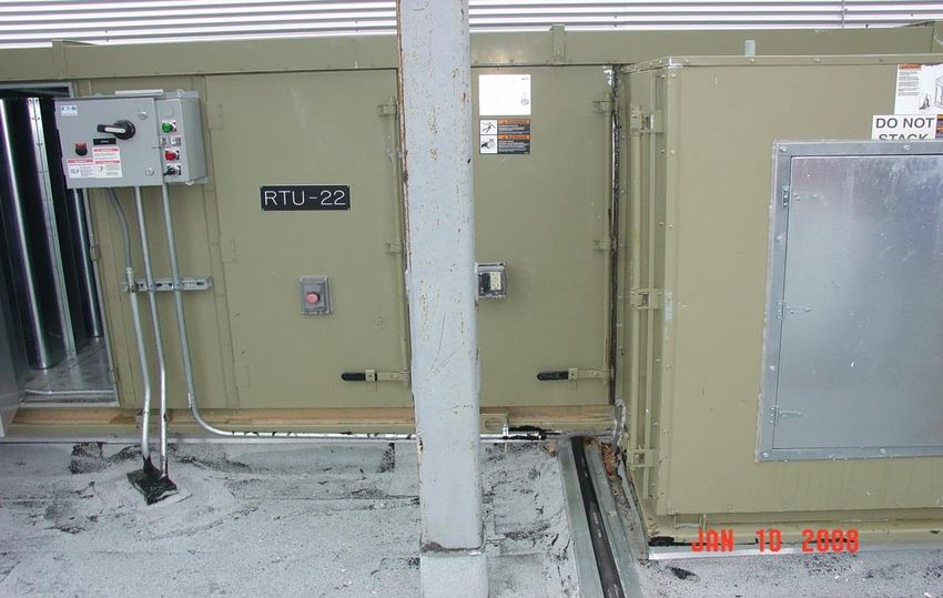
Roofing Design                                         Guidelines and Policies

                     ROOFING DESIGN
                 GUIDELINES AND POLICIES
                  FOR LOW SLOPE ROOFS

                     STATE OF NORTH CAROLINA
                  DEPARTMENT OF ADMINISTRATION
                    STATE CONSTRUCTION OFFICE

                                FIRST EDITION – 1988
                               SECOND EDITION – 2016

Low Slope Membrane Roof 2016                                           Page | 2
Roofing Design                                                       Guidelines and Policies

PREFACE

This criteria for roofing design is a compilation of data, policies, legal aspects,
preferences, experiences, prejudices, etc. that a Designer may find useful and necessary
in designing roofs and roofing systems and preparing contract documents relative to
roofing of State owned buildings.

This criteria is not a compendium of all roofing knowledge. It is not a State roofing
specification, not to be copied and printed or referenced in the Designer’s specifications.
It is a tool of communication between the State Construction Office, the Designer and the
User Agency to make the process easier and the end result more successful. The Designer
is to research the latest references, test data, product manuals, etc. and review the project
with local roofing contractors and manufacturer’s representatives in evaluating the
appropriate system to use.

Contrary to a popular and belief, the State Construction Office does not have an
“approved” list of roofing systems or manufacturers nor a “not approved” list. Any of the
roofing systems and materials that are included in this criteria will provide a good sound
roof when appropriately selected, designed and detailed by the Designer; when properly
installed by the Contractor, and properly maintained by the Owner. The Designer is hired
to evaluate all aspects of the building construction, function, site and budget, and to select
and prepare contract documents for a roofing system that will satisfy the design
requirements and reflect the latest in good roofing practice. State General Statutes require
that the Designer name at least three acceptable manufacturers that can provide the
specified system.

The State of North Carolina owns a wide variety of buildings that range from turkey
breeding barns to art and history museums, marine aquariums at the shore to magnetic
resonance imaging facilities at medical institutions; and lowland gorilla enclosures at the
zoo to maximum security prisons. There are also different levels of maintenance provided
at each facility. Many State owned building are unique buildings requiring well thought
out selections for roofing systems and detailing.

The State owns about 12,000 buildings. In a typical year the State Construction Office
may review between 200 to 300 projects that could roughly be divided into 1/3 new
buildings, or additions, 1/3 repair and renovation and 1/3 roofing replacement.

Low Slope Membrane Roof 2016                                                           Page | 3
Roofing Design                                                                            Guidelines and Policies

                                          Table of Contents

PREFACE ............................................................................................................. 3
CHAPTER 1               DEFINITIONS AND REFERENCES ........................................... 5
CHAPTER 2               GENERAL DESIGN ................................................................... 9
CHAPTER 3               BASIC CRITERIA..................................................................... 11
CHAPTER 4               ROOFING SELECTIONS ......................................................... 34
CHAPTER 5               NEW ROOF CONSTRUCTION ................................................ 40
CHAPTER 6               ROOFING REPLACEMENT ..................................................... 43
CHAPTER 7               GREEN ROOF.......................................................................... 48
CHAPTER 9               WARRANTY ............................................................................. 57
CHAPTER 10              SUSTAINABILITY .................................................................... 60
APPENDIX A ...................................................................................................... 63
APPENDIX B ...................................................................................................... 64
APPENDIX C ...................................................................................................... 66
APPENDIX D ...................................................................................................... 67
INDEX ................................................................................................................. 70

Low Slope Membrane Roof 2016                                                                                     Page | 4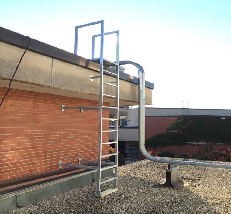
Roofing Design                                                     Guidelines and Policies

                                     CHAPTER 1

                       DEFINITIONS AND REFERENCES
1. General:

   This document made numerous references to The North Carolina State Building
   Code.” This code, for the purpose of this document, shall be known as the “Code.”

   The North Carolina State Building Code comprises seven (7) technical codes but only
   five (5) are pertinent to this document, North Carolina State Building Code; Building
   Code; Plumbing Code; Fire Prevention Code and Energy Conservation Code; North
   Carolina Existing Building Code.

2. Definitions:

   The two (2) dictionaries used to define the terms are the “Webster Dictionary” latest
   edition and the “Dictionary of Architecture and Construction” 4th Edition by McGraw
   Hill. Other definitions not in the dictionaries are from NCSBC, NRCA and
   SMACNA.

   A. Control Joint: A joint placed within a roof system to relieve stresses between
      adjacent systems which does no directly correlate to an expansion joint in
      primary building framing.

   B. Expansion Joint: A joint placed within a roof system to relieve structural
      stresses between adjacent structural framing which aligns with or otherwise
      correlates to and continues a break in the structural framing system and other
      components of the structural.

   C. Overburden: All items placed on the roof after a waterproofing membrane is
      completed on a green roof such as engineered soil, insulation, pavers etc.

   D. Overflow: Design method by which water is discharged from the roof when the
      primary roof drainage systems is not functioning or blocked.

   E. Roof: According to “Webster Dictionary” is the outside top covering of a
      building or structure that protects, shelters or guards.” For the purpose of this
      criteria, according to “Dictionary of Architecture and Construction” 4th Edition
      by McGraw Hill,” the top covering of a building, including all materials and
      constructions necessary to support it on the walls of the building or uprights;
      provides protection against rain, snow, sunlight, extremes of temperature and
      wind.

   F.   Roof Deck: Can be of any construction material including wood, metal decking
        and concrete. It is the flat or sloped surface not including its supporting members

Low Slope Membrane Roof 2016                                                         Page | 5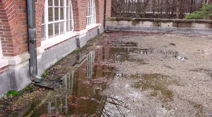
Roofing Design                                                     Guidelines and Policies

        or vertical supports. The deck supports the non-load bearing components such as
        insulation, membrane, flashing etc.

   G. Roof Drain: A drain designed to receive water collecting on the surface of a roof
      and to discharge it into a leader or a downspout.

   H. Roof Drainage System: On the roof of a building, a system composed of storm-
      water collection devices, and piping connected to these collection devices;
      transports the rainwater off the roof, out and away from the building.

   I.   Roofing: Any material (or combination of materials) used as a roof covering,
        such as membrane, corrugated metal, sheet metal, shingles, slate, thatch, tiles and
        membrane; usually provides waterproofing and wind protection.

   J.   Roof Recover: The process of installing an additional roof covering over a
        prepared existing roof covering without removing the existing roof covering – as
        defined in NCSBC.

   K. Roof Repair: Reconstruction or renewal of any part of an existing roof for the
      purposes of its maintenance.

   L. Roof Replacement: The process of removing the existing roof covering,
      repairing any damaged substrate and installing a new roof covering.

   M. Scupper: A means of drainage consisting of an opening through a wall/parapet
      lined with sheet metal to allow the passage of water.

   N. Vapor Retarder: An impervious membrane placed in the roof system to retard
      or prevent the passage of water vapor.

   O. Vegetated Roof Assembly: A waterproofed substrate with plantings/landscaping
      installed above.

3. References:

   The references listed publications/entity are basic essentials to proper design and
   detailing of a roof.

   A. State Construction Office (SCO)
      North Carolina State Construction Manual
      301 N. Wilmington Street, Suite 450
      Raleigh, NC 27601-1058
      Phone Number: (919) 807-4100
      Fax: (919) 807-4110
      Web Site. http://www.nc-sco.com

Low Slope Membrane Roof 2016                                                        Page | 6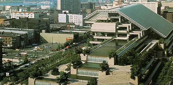
Roofing Design                                               Guidelines and Policies

   B. State Construction Office (SCO)
      North Carolina State Building Code: Building Code              (NCSBC)
      North Carolina State Building Code: Existing Building Code     (NCEBC)
      North Carolina State Building Code: Mechanical Code            (NCMC)
      North Carolina State Building Code: Plumbing Code              (NCPC)
      North Carolina State Building Code: Fuel Gas Code              (NCFGC)
      North Carolina State Building Code: Fire Prevention Code       (NCFPC)
      North Carolina State Building Code: Energy Conservation Code   (NCECC)
      301 N. Wilmington Street, Suite 450
      Raleigh, NC 27601-1058
      Phone Number: (919) 807-4100
      Fax: (919) 807-4110
      Web Site. http://www.nc-sco.com

   C. North Carolina General Assembly (NCGA)
      North Carolina General Statute Website:
      http://www.ncleg.net/gascripts/statutes/Statutes.asp

   D. National roofing Contractors Association (NRCA)
      National Roofing Contractors Association Roofing Manual; Membrane Roof
      System
      Green Roof Systems Manual
      10255 W. Higgins Road, Suite 600
      Rosemount, IL 60018-5607
      Phone Number: (847) 299-9070
      Fax: (847) 299-1186
      Website. http://www.nrca.net

   E. Sheet Metal and Air-Conditioning Contractor’s National Association, Inc.
      (SMACNA)
      4201 Lafayette Center Drive
      Chantilly, VA 20151-1209
      Phone Number: (703) 803-2980
      Fax: (703) 803-3732
      Website. https://www.smacna.org/

   F.   Underwriter’s Laboratory (UL)
        2600 N.W. Lake Road
        Camas, WA 98607-8542
        Phone Number: (877) 854-2577
        Fax: (360) 817-6278
        Website: http://www.ul.com/global/eng/pages/

   G. Factory Mutual Global (FM)
      Presto Ridge III
      3460 Preston Ridge Road, Suite 400

Low Slope Membrane Roof 2016                                                 Page | 7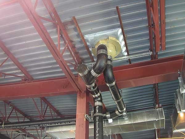
Roofing Design                                            Guidelines and Policies

        Alpharetta, GA 30005
        Phone Number: (770) 777-3600
        Fax: (770) 777-0414
        Website http://www.fmglobal.com

   H. American Society of Heating, Refrigerating and Air-Conditioning Engineers
      (ASHRAE 90.1)
      36588 Treasure Center
      Chicago, IL 60694-6500
      Phone Number: (800) 527-4723
      Website http://www.ashrae.org/resources--publications/

   I.   Single Ply Roofing Institute (SPRI)
        465 Waverly Oaks Road, Suite 421
        Waltham, MA 04252
        Phone Number: (781) 647-7026
        Fax: (781) 647-7222
        Website http://www.spri.org

   J.   Roof Consultants Institute (RCI)
        1500 Sunday Drive, Suite 204,
        Raleigh, NC. 27607
        Phone Number: (800) 828-1903
        Fax: (919) 859-0742
        Website http://www.rci-online.org

   K. NSF International
      P.O. Box 130140
      789 N. Dixboro Road
      Ann Arbor, MI. 48105
      http://www.nsf.org/

Low Slope Membrane Roof 2016                                              Page | 8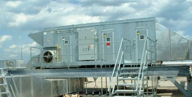
Roofing Design                                                      Guidelines and Policies

                                      CHAPTER 2

                                 GENERAL DESIGN

1. Purpose

   The purpose of this manual is to establish a minimum design standard for facilities
   owned by the State of North Carolina. This document is not intended to be a State
   roofing specification or a summary of the North Carolina State Building Code or the
   authority on low slope membrane roofing. Designer is solely responsible for ensuring
   compliance with all applicable codes and standards.

2. Designer Responsibility

   A. State projects involving roofing shall use and follow the Department of
      Administration document “Roofing Design Guidelines and Policies” only for the
      purpose of preparing the designer’s plans and specifications for their specific
      project. This document is not written in contractual language for bidding
      purposes and/or contractual enforcement and is NOT to be inserted into the
      specification.

   B. It is the Designer’s responsibility to be well versed with all relevant criteria in the
      State Construction Office “Roofing Design Guidelines and Policies.” This and
      other guidelines are available on the State Construction Office website.

   C. If the roofing project is a ‘stand-alone’ project, review the State Construction
      Office Manual for documentation and bidding requirements.

   D. Modified version of the Building Code Summary, Appendix B, For All
      Commercial Roof Projects – this document is intended to summarize the
      minimum requirement by State Construction Office for roofing projects on State
      Owned facilities. It does not modify the requirements of the Building Code. The
      designer of record is responsible to ensure all roofing projects conform to the
      minimum requirement of the Code.

   E. Design Calculations – The Designer is record is responsible for performing all
       necessary design calculations to ensure compliance with the Code. Calculations
       should be sealed by a licensed Engineer in the State of North Carolina and
       maintain in the Designer’s project files. Design calculations should include:
      a. Dead Load
      b. Wind Uplift Pressures
      c. Primary Drainage
      d. Secondary (Emergency Overflow) Drainage
      e. R-value
      f.   Dew Point Analysis

Low Slope Membrane Roof 2016                                                          Page | 9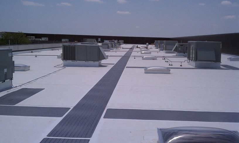
Roofing Design                                                      Guidelines and Policies

3. Protection and Safety

   A. The majority of roofing projects occur on occupied existing building, the
      Designer shall explore components and systems not only from a performance
      standpoint but also for life safety.

   B. Consideration should be given to the inventory of the building, and incorporate
      components and system as necessary to protect those contents. This is especially
      true with laboratories, storage/warehouse etc.

4. System Selection

   roofing system should be selected based on the intended use of the facility. Designers
   should consult with State building Owner/Users to determine the specifics of the
   facility that affect roof system selection (anticipated future use, service, life rooftop
   equipment, etc.)

5. Energy

   A. The minimum roof insulation shall meet the requirements of the North Carolina
      State Energy Conservation Code (NCECC) or the mandatory provisions of
      ASHRAE 90.1-2010 or GS143-138 for existing building.

        1. New buildings and major additions – Roof insulation shall meet the
           requirements of the current NC Energy Conservation Code.

        2. Existing Building – SL 2014-90 9GS 143-138) allows the application of the
           2009 North Carolina Energy Conservation Code to existing buildings that
           were construction prior to January 1, 2012 and subsequent additions of up to
           50% of the original floor area, instead of the 2012 North Carolina Energy
           Conservation Code. The 2009 North Carolina Energy Conservation Code has
           significantly lower insulation requirements than the 2012 code.

        3. North Carolina Existing Buildings Code, Section 908 – alterations to existing
           buildings are permitted without requiring the entire building to comply with
           the energy requirements of the North Carolina Energy Conservation Code.
           The alterations shall conform to the energy requirements.

   B. The minimum thermal resistance of the insulating material installed either
      between the roof framing or continuously on the roof assembly shall be as in the
      Code.

   C. Insulation installed on a suspended ceiling with removable ceiling tiles shall
      NOT be considered part of the minimum thermal resistance of the roof insulation
      according to NCECC.

Low Slope Membrane Roof 2016                                                        Page | 10
Roofing Design Guidelines and Policies
CHAPTER 3
BASIC CRITERIA
1. Purpose and Use
A. Any roofing system that is properly selected based on intended use of the facility,
properly designed, properly installed and properly maintain should function for a
long time.
B. Low slope roof systems for state owned facilities should be designed for life
expectancies of 20 years or more unless other criteria have been established for a
specific facility.
C. Pedestrian plazas and vegetative roof gardens are uncommon on State owned
facilities. When such system is justified and approved by the owner they shall be
designed by professionals specifically experienced in such systems. The system
shall be designed to comply with all other roof system requirements in this
criteria. Designer should give consideration for additional cost, difficulty
associated with replacement of such systems in the future and a system that has a
life expectancies of 30 years or more.
D. Gravel ballasted roof assemblies are discouraged unless the ballast are concrete
pavers.
E. Annual maintenance costs should be taken into account for selection and design
of all roof systems. Access drains, flashings, equipment and other items requiring
routine inspection and maintenance should be assured in all design.
2. System Selection
Roofing shall be selected based on the intended use of the facility. Consult with the
building Owner/Occupants to determine the specifics of the facility that affect roofing
selection such as use for today, anticipated future use, service life, sustainability, and
rooftop equipment.
3. Slope
A. A minimum requirement of ¼ inch per foot slope is required by NCSBC. There
should be no ponding on the roof. Any water that does not drain must evaporate
within 48 hours.
B. Reroofing is not required to meet the minimum design slope requirement of one-
quarter unit vertical in 12 unit horizontal (2-percent slope) in the Code for roofs
that provide positive roof drainage. However, it is encourage to maintain a
Low Slope Membrane Roof 2016 Page | 11Roofing Design Guidelines and Policies
minimum of ¼” per foot slope.
C. Positive drainage should be designed in all valleys with crickets. Valleys shall
have the same minimum slope as the adjacent roofing.
Picture 1 – Standing water must evaporate within 48 hours
D. Roof garden, plaza and pedestrian walks are NOT exempt from the roof slope
requirement. The code does not have an exception in permitting the use of a dead
flat roof. This type of use, plaza/garden/pedestrian walk/water feature, is over an
occupiable space and is the roof for that space below.
Picture 2 – Garden, plaza, walkway, water feature etc. are roofs of the building
Low Slope Membrane Roof 2016 Page | 12Roofing Design Guidelines and Policies
E. Roof framing should be sloped to achieve the desired slope per Code. This
creates a uniform thickness of roof insulation and reduce the amount required to
built-up the slope.
Picture 3 – Low slope roof with built-in or framed-in slope
4. Roof Mounted Equipment
A. Avoid roof mounted equipment whenever possible or utilize the roof penthouse
or design the top floor as a mechanical floor. If that is not economical the
following minimum requirement shall be met.
1. Equipment shall be supported on a properly constructed curb or an elevated
metal frame.
Picture 4 – Rooftop equipment curb
Low Slope Membrane Roof 2016 Page | 13Roofing Design Guidelines and Policies
2. Curbs shall extend a minimum 8 inches on the high side above the finish
roof surface.
3. Curbs shall be properly flashed with a two (2) piece type flashing that will
facilitate re-roofing in the future or the equipment to be set atop it includes a
cover with turn down edge forming a flashing.
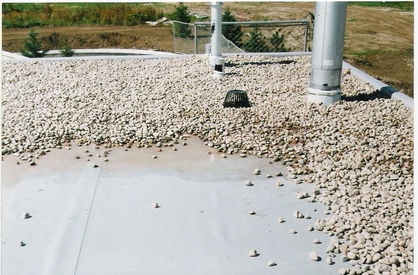
4. Metal frames or platform should be used to support large or heavy
equipment on the roof surface. Steel columns shall be connected directly to
the building super structure. Steel penetrations shall be flashed. The flashing
system may be pre-manufactured “boots” or draw bands with sealant on top
or welded metal bonnet.
Picture 5 – Mechanical platform or frame
5. Metal steps that are part of the frame platform should be suspended from the
platform and not set on the roof surface. This reduces the number of roof
penetrations.
6. Where metal frames are utilized to elevate equipment above the roof surface,
frames shall be constructed with sufficient clearance to allow roofing
installation to occur beneath the frames in a safe and efficient manner.
7. Walk-pads shall be included leading from the roof access to platform steps,
equipment requiring service and inspection.
Low Slope Membrane Roof 2016 Page | 14Roofing Design Guidelines and Policies
Picture 6 – Rooftop walk-pads and at equipment service panel.
5. Access
A. Access to a roof is required by Code for life safety and insurance reasons but is
also necessary for routine rooftop mounted equipment inspection, service and
maintenance. A multi-level roof shall have ladders mounted on wall between
levels or roof access doors that are available on each floor adjacent to the roof.
Picture 7 – Roof ladder. Not anchored to the roof.
Low Slope Membrane Roof 2016 Page | 15Roofing Design Guidelines and Policies
B. Permanent fixed ladders shall be utilized. The use of portable ladders on roof is
discouraged since ladders have sharp edges that will damage the roofing
membrane and deform the roof edge or parapet flashing. It can become a flying
object in strong gust or hurricane.
C. Roof access doors/hatches shall have locks with key operations. A warning sign
measuring 14”x18” shall be mounted adjacent to the roof access in Red letters
and White background to read “NO ACCESS – Authorized Personnel Only.”
D. If access is required by Code, such as the extension of the stairway to the roof in
buildings four or more stories, then the lockset must be connected to the fire
alarm system for un-latching.
E. Fall protection at open Roof Access Hatch is not required by Code but is required
by OSHA. It is strongly advised that fall protection system be specified in your
specifications and detailed in the drawing set to avoid potential change order.
Picture 8 – Roof hatch. Note the fall protection system required by OSHA around the hatch
opening with a self-closing gate frame
F. Provide guardrails where Roof Access Hatch opening located within 10 feet of a
roof edge in accordance with NC Building Code.
Low Slope Membrane Roof 2016 Page | 16Roofing Design Guidelines and Policies
Figure 1 – Guardrail required where roof hatch opening is less than 10 feet from roof edge
6. Vapor Retarders
The NRCA and major roofing material manufacturers recommend serious
consideration of vapor retarder on any roof where the outside average January
temperature is 40 degrees F or less and the interior relative humidity will be 45% or
greater. The responsibility lies with the Designer to determine if the conditions will
apply to his project. Built-up roofs are sensitive to trapped moisture, and the contact
adhesives used in numerous single-ply membrane are sensitive to moisture. Many
State facilities can meet the 45% limit on humidity and the western half of the state
can reach the low temperatures. Examples of facilities with high humidity would be
laundries, cafeteria/kitchens, natatoriums, athletic facilities, “process” plants,
dormitories etc.
A. Unusually high interior humidity (examples; kitchen, laundries, natatoriums,
etcetera), combined with exterior low winter temperatures can result in strong
vapor drive towards the exterior resulting in condensation and dripping. The
condition can be reverse where the interior needs to be kept at extremely low
temperatures (example; built-in cold storage room), the roof membrane itself must
function as a vapor retarder since it is now on the warm humid side of the roofing
system
B. In order to be effective, vapor retarder must be warmer than the dew point
temperature. It is installed on the insulation warm side to minimize vapor
migration into the roof system.
C. Care should be taken to ensure all gaps or openings are sealed during installation
of the vapor retarder to ensure no moisture migrate through those small
gaps/openings.
Low Slope Membrane Roof 2016 Page | 17Roofing Design Guidelines and Policies
D. Designer shall analyze and rationalized the inclusion or exclusion of the vapor
retarder carefully prior to making a roof selection and design. Presently there are
various design aids available for Designer’s use from proprietary software to
manufacturer programs.
E. If vapor retarder is needed on State facility with a metal deck, the deck must be
covered with a mechanically fastened layer of minimum 5/8” fire-rated water-
resistant gypsum board to provide a smooth attachment surface for the vapor
retarder.
F. If vapor retarder is used the vapor retarder must be compatible with the roofing
system selected.
G. Detail information on this subject is available in the NRCA Roofing Manual.
7. Wood Blocking and Nailer:
A. Wood blocking, nailer and non-structural wood materials used in roofing shall be
preservative-treated with water-borne preservatives in accordance with AWPA
U1 and M4 for the species, product, preservative and end use.
B. Wood for blocking or nailer shall be kiln dry after treatment to a moisture
content of 19% or less.
C. The treated wood shall bear the quality mark of an inspection agency.
D. Details to minimize the thickness and number of layers of treated wood blocking.
1. Premanufactured curbs are suggested over stacked wood blocking for
rooftop units.
2. For excessive edge construction heights, consider a knee wall in place of
stacked wood blocking.
8. Expansion Joint
A. The inclusion of membrane expansion joint in the roofing system is to reduce
stress and accommodate the movement of the building components to limit the
effect of possible tear and buckling of the roofing membrane. Each building
component has its own coefficient of expansion and contraction subject to
varying temperature changes resulting in thermal movement. It is the Designer’s
responsibility in their design to take into consideration the following:
1. Building’s thermal movement characteristics.
2. Structural support and roof deck.
3. Roof system selected or in place.
Low Slope Membrane Roof 2016 Page | 18Roofing Design Guidelines and Policies
4. Climatic conditions.
5. Rooftop units.
6. Roof drainage.
Picture 9 – This roof expansion joint will not function as intended
B. The membrane expansion joint in the roofing shall occur at the same location as
the building expansion joint. The building expansion joint through the building
must be filled with fire safing material in fire rated construction to comply with
the Code and substantiate by selected test standard.
C. Expansion joint shall be designed to accommodate expansion and contraction.
The joint shall be detailed with wood blocking to a height of 8 inches above the
finish roof surface. Ensure the “built-up joint” does not impede roof drainage.
D. Low profile expansion joint designed to be installed in the plane of the roofing
membrane is not recommended due to its exposure to foot traffic during and after
construction.
9. Area Divider
Area dividers perform important functions as parts of the roof system. For example,
in regions where there are periods of freeze-thaw cycles, area dividers may be used to
relieve thermal stresses on the roof systems where expansion joints are not required.
Also, when roofing is done in sections or stages, area dividers can be used to separate
roof system sections that differ in age or type. It can also isolate specific area on the
roof such as ripped roofing around penetrations.
Area divider is very similar to Expansion Joint. Care must be exercised in locating
Low Slope Membrane Roof 2016 Page | 19Roofing Design Guidelines and Policies
primary and secondary roof drainage systems for each of those areas.
10. Building Code
The NC Department of Insurance is the insurer of State owned buildings. The NCSBC
is the minimum requirement that satisfy 2 parameters, internal and exterior fire
exposures. NC Department of Insurance may require or request a higher standard.
The roof surfaces on State owned building shall be Class A or Class I.
A. External Fire Resistance
Roof assembly is susceptible to ignition due to exposure to heat or flying burning
brands from adjacent fire. The roof membrane provides the protection from
external fire and therefore must be investigated and evaluated. The burning
characteristics of roof surface, UL Class A, B or C and FM Class I. Roof surfaces
on State Buildings need to be Class A or Class I.
Class A, B or C with UL label are tested with ANSI/UL 790 while FM Class I is
tested with ASTM E108. Single ply membrane has difficulty passing these tests
without either external protection such as ballast, pavers, coating, or overboard.
The following link provides additional information of the tests and “Conclusions
and Recommendations.”
http://staticcontent.nrca.net/masterpages/technical/techbull/0106_firetesting.pdf
B. Internal Fire Resistance
1. A roof assembly is susceptible to propagating an internal fire by contributing
fuel through liquids or gases. For roof assemblies, the ceiling assembly and
the structural deck provide the protection from an internal fire.
2. Designer shall determine the level of fire protection require for various
construction types by using “Fire Resistance Rating Requirements for
Building Elements” Table in Chapter 6 NCSBC.
3. Hourly rating requirements for specific building elements in new construction
are satisfied by selecting tested assemblies that provide the minimum
protection as determine by approved testing agencies.
4. Tested fire rated assemblies are available for downloading from internet
website such as UL Underwriters Laboratory. Other testing agencies website
are also available. The UL website has some requirements that must be
followed if the designer elects to download the test report. UL permits the
reprinting of their report provided a statement is added to the reproduction.
Note: The only way that UL Details can be accurately presented in the
drawings as tested is to reprint the information from the UL Fire Resistance
Directory. The details must not be manipulated in any way or form. The
Low Slope Membrane Roof 2016 Page | 20Roofing Design Guidelines and Policies
reprint of their Designs and Details on drawings are subject to their
requirements including the following conditions to protect their copyright: 1)
The System/Design must be presented in entirety and in a non-misleading
manner, without any manipulation of the data, 2) a statement must appear
adjacent to the extracted material indicating that it is “Reprinted from 20XX
Fire Resistance Directory (or whichever title is applicable) with permission
from Underwriters Laboratories, Inc.” and 3) the reprinted material must
include a copyright notice stating “Copyright 20XX Underwriters
Laboratories, Inc.”
5. A layer (thermal barrier) of exterior Type “X” gypsum board is required on
metal decks under 1½” thick foam plastic insulation or the foam plastic
insulation is part of Class A, B or C roofing cover with the foam plastic
insulation satisfactorily passes FM4450 or UL1256 tests.
6. Stand alone roof replacement project shall include a modified Building Code
Summary for Roofing Projects available on the State Construction Office
website.
C. Wind Uplift Resistance
1. The tests and ratings for roof have been around a long time and are commonly
misunderstood by designers and contractors alike. The two tests are FM
Standard 4470 and UL580. Neither of these tests correlated with wind speed
as thought to be.
2. FM4470: In this test, the specimen is attached to the test apparatus according
to the manufacturer’s particular attachment specification. Positive air pressure
is exerted on the sample from the underside of the apparatus (to simulate
uplift).
The test pressure starts at 30 psf and maintained for one minute. If the sample
can withstand the full minute, the pressure is increased by 15 psf. The test
continues with increase of pressure by 15 psf for each additional minute until
the membrane split or snap.
If the membrane can withstand a 60 psf load/pressure for 1 minute, the system
will receive a rating of FM-60. Thus FM-90 means the membrane can
withstand a 90 psf load/pressure for 1 minute.
However, FM throws in a safety factor of 2. That means FM-60 is approved
for use in uplift design of up to 30 psf. Likewise, FM-90 is approved for use in
uplift design of up to 45 psf.
The “I” in FM I-60 is not an “I” but a Roman Numeral “1.” This “1” or “I”
means the membrane also passed other tests including fire resistance.
3. UL 580: The test by UL is for wind resistance only and issues ratings as Class
30, 60 and 90.
To receive a Class 30 rating, the membrane must remain intact for 80 minutes
period at specific positive, negative and oscillating pressures.
Low Slope Membrane Roof 2016 Page | 21Roofing Design Guidelines and Policies
For Class 60 rating, an additional 80 minutes (total 160 minutes) of test as in
Class 30 is carried out.
For Class 90 rating, an additional 80 minutes (total 240 minutes) of test as in
Class 60 is carried out.
4. Ballasted type roofing is not encouraged due to the fact that loose laid ballast
becomes missiles in high wind condition which translate to more liability for
the State. It is also difficult to inspect and maintain and may be costly to
repair. Displaced ballast may not be evenly distributed after repair thus
exposing sections of the roofing membrane to UV light. Should the owner
have a strong desire to utilize this system, a concrete paver system is
preferred.
Picture 10 – Ballasted roof with washed or blown ballast exposing roofing membrane
D. Design Loads
1. Wind Loads for structural design are in Chapter 16 NCSBC.
Note: Add 10 mph to the appropriate velocity for State facilities. The State
Building Code is based on a 50 year occurrence and the State underwriters
prefer a 100 year occurrence.
2. Live Loads for structural design are in in Chapter 16 NCSBC.
3. Dead Loads for structural design shall be increased by 10 psf to cover future
increases in actual dead loads. See “Roof Add-On” items below.
11. Lightning Protection
A. Lightning protection systems are not required by the Building Code.
Low Slope Membrane Roof 2016 Page | 22Roofing Design Guidelines and Policies
B. The installation of lightning protection system is an Owner’s option that is worth
consideration. New system shall comply with the NEC and NFPA. Existing
lightning system should be replaced and/or upgraded in conjunction with roof
replacement. Installation of components require the supervision of a qualified
lightning protection contractor. Components that penetrate any portion of the roof
structure should be adequately flashed. Recertification programs are available
from Underwriters Laboratories (UL) and Lightning Protection Institute (LPI).
12. Construction Details
There are numerous typical conditions on a roof and numerous conditions unique to
the roof. It is not the intent of these criteria to cover all conditions but to point out
some of the common errors that are repeated on State roofing projects.
Designer should be aware, reproducing details from standards and manufacturers
standards or referencing all details to standards are not acceptable. It may be in
violation of “GS.133-2 Drawings of Plans by Material Furnisher Prohibited”. Roofing
details must be drawn to scale and be project specific.
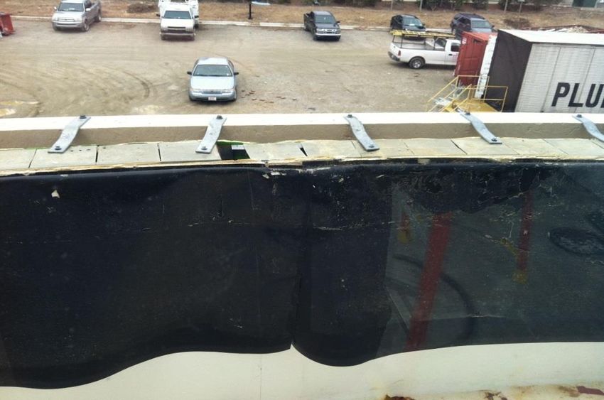
A. Metal Coping
1. The horizontal top surface of the roof parapet is vulnerable to water
penetration if not properly built. A piece of roofing underlayment or roofing
membrane shall be placed on top of the wood block prior to installing the
metal coping.
The addition of this piece of underlayment or roofing membrane is vital in
preventing water intrusion into the cavity of the cavity wall.
Picture 11 – The wall cavity must be protected from water intrusion.
Low Slope Membrane Roof 2016 Page | 23Roofing Design Guidelines and Policies
2. The top of the metal coping shall slope ¼” per foot to the roof side.
3. Lapped seams or butt joints of metal copings should not be used.
4. Parapet flashing (coping) failure is due to its weakness in resisting the
outward and upward pressures of the wind. The cleat or hook at the detail is
attached too far up the wood nailer thus providing good leverage for the wind
to apply outward and upward pressures at the lower edge. If the cleat/hook
and metal edge is of insufficient gage, the coping will be ripped open
exposing the top of parapet. Securing the lower portion of the cleat/hook
closer to the lower edge of the flashing and increasing the metal gage may
prevent this from happening.
5. The metal coping shall be secured on both sides of the parapet by continuous
cleats on the outside and other attachments on the roof side. The lower edge of
the coping on both exterior and interior side shall extend a minimum 1 inch
below the parapet wood blocking.
Pictures 12 and 13 - Wind damaged metal coping at lapped joint.
B. Roof Edge Flashing
Metal edge flashing failure is due to its weakness in resisting the outward and
upward pressures of the wind. The cleat or hook secured at the fascia is attached
too far up from the bottom of the vertical portion of the flashing thus providing
good leverage for the wind to apply outward and upward pressures at the bottom
edge. If the cleat/hook and metal edge is of insufficient gage, the flashing will be
ripped open exposing the edge of the roofing system. Care shall be exercise in
locating the continuous cleat and the appropriate metal gage specified. NCSBC
requires the edge securement for low-slope roofs to be tested in accordance with
ANSI/SPRI ES-1.
C. Wall/Roof Flashing
Roofing shall terminate under a two piece type wall flashing and counter flashing.
This is to facilitate re-roofing in the future without having to tear out the whole
flashing system.
Low Slope Membrane Roof 2016 Page | 24Roofing Design Guidelines and Policies
A bath tub does not leak unless the drain is not properly installed. The roof shall
be designed as if designing a “bath tub.” This minimizes the number of “roof
penetrations” hence eliminating potential leakage.
1. There is a current trend to use roofing membrane as exterior wall finish. Roof
membrane is manufactured for “horizontal” application and is also tested
horizontally. It is NOT an exterior “wall” finish material and is NOT an
industry standard. Re-roofing will require the vertical portion of the roofing be
replaced at the same time due to exposure to UV light as well as other air
borne contaminants. If the intent is to reduce construction cost, the
replacement cost will eventually cost more than a finish wall material. That
being the case, any wall two (2) feet above the roof shall be built as a wall
with exterior wall finish.
Picture 14 – Roof membrane used as wall finish is not acceptable by this guideline.
2. NRCA details require that a two piece type wall flashing and counter flashing
shall be set not less than 8 inches above the finish roof surface nor more than
24 inches maximum above the finish roof surface. Where wall conditions
require additional protection, metal panels or other cladding shall be utilized.
3. The portion of the through wall flashing within the wall cavity shall be lapped
by the vapor/air barrier to ensure no water is directed behind the metal
flashing.
4. Exposed Termination Bar must not be used to terminate roofing membrane
onto a brick masonry or CMU wall. They are usually used on smooth
watertight surfaces. Sealant is your only protection and it does not adhere well
to masonry, CMU and mortar joints. Installation is usually poorly done.
Low Slope Membrane Roof 2016 Page | 25Roofing Design Guidelines and Policies
NRCA, SMACNA and BIA recommend cutting a raggle 1-1/2 inch deep in
(existing condition) masonry joint and inserting flashing with wedges and
sealant fill. [The depth of the raggle is dependent upon the thickness of the
masonry/cmu wall]
There are two conditions when Termination Bar can be used. When it is
protected from the weather and where Termination Bar is used to terminate
the roofing membrane on a smooth concrete wall with appropriate sealant on
top.
D. Roof Penetrations
NRCA recommends a minimum of 12 inches of clearance between pipes; a
minimum of 12 inches clearance between pipe and curb or wall; and a minimum
24 inches between curb and wall to facilitate proper installation of the roof and
flashing. Multiple pipe penetrations should be ganged through a penetration
pocket. See NRCA recommendation.
Figure 2 – NRCS recommend the clearances for pipe/wall parapet/curb
1. Penetration flashings should include prefabricated boots or sheet metal
flashing systems to conform to the profile of the penetrations.
2. Pitch pockets are discourage, however, when necessary due to conditions,
sheet metal hoods should be fabricated to fully cover the base.
3. Multiple pipe penetrations should be ganged through a fabricated metal box
with penetrations entering the box on the vertical sides.
Low Slope Membrane Roof 2016 Page | 26Roofing Design Guidelines and Policies
13. Drainage System
A. General
1. Roof drainage is accomplished through the use of primary roof drains, gutters
and secondary drainage system in the event the primary systems becomes
blocked. The size and roof area requirement for both internal and external
drainage of building roof is covered in the North Carolina Plumbing Code
(NCPC-Chapter 11).
2. Roof drainage should be carefully designed whether the proposed roof system
is in conjunction with retrofit applications or new construction. Where
existing tapered roof slopes are revised, drainage capacities should be verified
to ensure existing pipe systems can adequately carry required discharge.
Water that is not efficiently removed from the roof is more likely to find its
way through membrane defect such as open base flashing lap, etc. should any
exist. Moisture that enter the roof assembly can lead to reduced insulation
thermal properties, damaged and deteriorated substrate components, and
potential indoor air quality concern.
Picture 15 – Main roof drain and overflow drain combination.
3. Building owners should be contacted regarding their specific preferences as to
type of drainage system to be installed on their structure.
4. Drainage onto sidewalks or pedestrian paths should be controlled or
eliminated, particularly in locations where frozen precipitation is anticipated.
5. Internal drainage systems with PVC leaders are not permitted in fire rated
construction, non-combustible buildings or ceiling spaces used for return air
HVAC. Designer shall review the NCPC and NCMC.
Low Slope Membrane Roof 2016 Page | 27Roofing Design Guidelines and Policies
6. Combination type primary/secondary drains that share a common strainer are
not acceptable on State roof. If the roof strainer gets clogged, both primary
and secondary drainage will be out of commission.
B. Primary Roof Drainage
1. Low Slope Roof Drain
a. Roof drains shall conform to ASME A112.21.2M or ASME A112.3.1.
Roof drains are required to have strainers extending no less than 3” above
adjacent roofing. Metal strainers should be considered for longevity. Drain
inlet area is to be no less than 1½ times the area of vertical leader to which
the drain is attached per NCPC.
b. Vertical drain leaders for primary drains shall be sized based on 100-year
hourly rainfall rates map or other local weather data. Size drains for
maximum projected roof area in accordance with drain leader size tables
in Chapter 11 NCPC. Where vertical walls divert rain water on the roof, ½
of the vertical wall area shall be added to the projected roof area.
c. Horizontal drain leaders (based on pipe slope) using drains and leader
sizing see table in Chapter 11 NCPC. Most roof drainage systems are
limited by the capacity of the horizontal conductors. For re-roofing
projects, designer should exercise reasonable care in an attempt to
determine the adequacy of existing horizontal leaders or other drainage
system components to remain.
d. Roof drain capacities should be verified for both new construction and
roof replacement.
e. Roof structure shall be designed to support the load of rainwater
accumulated to the elevation of the secondary drainage system plus the
uniform load caused by water that rises above the inlet of the secondary
drainage system at its design flow determined by the Code. The roof shall
also be checked for ponding instability in accordance with the Code.
f. Retrofit roof drains are allowed when necessary du tot existing conditions.
g. Drainage calculations should be included on the drawing for both new
construction and for re-roofing.
2. Gutters
a. Rectangular (hanging) gutters and downspouts are generally sized using
Chapter 1 of SMACNA. Gutters should be formed of corrosion resistant
materials of adequate gauge based on total girth.
Low Slope Membrane Roof 2016 Page | 28Roofing Design Guidelines and Policies
b. Hanging gutters are “hung” or installed along the roof edge are visible.
Support hangers are installed under the gutter and against the wall with
spacers.
c. Gutter lengths are generally limited to 50 feet with a minimum of one
downspout per gutter section. Expansion joints are centered between
downspouts.
d. Based on the size of the roof area to be drained and the rainfall intensity
for location, the size of gutters and downspouts should be calculated as
required by Code.
e. Gutters with semicircular cross section should be avoided unless to match
existing conditions can be sized per Chapter 11 NCPC.
f. The front edge of hanging gutter should be at least 1” lower than the back
edge. This is recommended so that water will flow over the front edge in
the event of the gutter becomes clogged.
g. Concealed gutters are not visible and are designed to be embedded into the
roof structure. This type of gutters is difficult to build, maintain and repair.
More often than not, damage due to leaks is not apparent until severe
damage has occurred and is costly to repair. The use of, in new structure,
concealed gutters is NOT encouraged. However, project specifics may
dictate this use. Special care must be exercised while designing and
constructing concealed gutters because unlike hanging gutters, any leaks
that occur will likely enter the structure and damage substrate components.
Mockups shall be built. Completed construction shall be flood tested for a
minimum of 24 hours.
3. Eaves/Roof Edge
Roof drainage is allowed over roof eaves where the roof area is small such as
canopies etc. Allowing water to drain over eaves can cause roof water to
cascade down the exterior walls which can lead to staining and/or
deterioration. The resulting “splash” at grade can negatively (erosion) affect
soil/turf adjacent to the structure. It is preferable to use water management
systems unless specific site conditions restrict the use of such components.
Gutters or drains help to divert water to predetermined locations. Additionally,
allowing water to flow over eaves also creates the potential for excess water to
create icy conditions that could be hazardous to pedestrians.
4. Scuppers
a. Scuppers are acceptable for use as primary drainage system but shall
include conductor heads and downspouts to control and direct water off
Low Slope Membrane Roof 2016 Page | 29Roofing Design Guidelines and Policies
the roof. Conductor head shall be installed with the head at a minimum 1
inch below the scupper outlet. If the installed higher than the scupper
opening shall include an opening at the face of the conductor head to act
as an emergency outlet as recommended by SMANCA.
b. Scupper shall be sized according to NCPC. The minimum horizontal
opening dimension shall be 4 inches but 6 inches is preferred for ease of
construction.
C. Secondary Roof Drainage
a. Secondary drainage is required when roof edge construction will not allow
water on the roof to exit the roof if the primary drainage is blocked or is
otherwise disabled. Overflow drains or scuppers shall be sized to prevent
ponding water from exceeding that for which the roof was designed.
b. The overflow drainage system is required by Code to be totally separate
system from primary systems so that they can remain functional should the
primary drainage become obstructed. Discharge of secondary drainage shall
be located where easily observed by the maintenance crews or occupants.
Chapter 11 NCPC. However, do not locate overflow discharge above exit
doorways or at pedestrian walkway where freezing/icing condition can occur.
Picture 16 – Main roof drain and overflow drain have independent drainage system and
discharge below roof
c. The drainage system shall be designed in accordance with rainfall rates in
Chapter 11 NCPC for 100 years 15 minutes rainfall duration.
d. Scuppers shall be set 2 inches above the primary drain intake with a minimum
horizontal opening dimension of 4 inches (6 inches is preferred). The use of
round scupper opening shall be limited to historical or existing structures
Low Slope Membrane Roof 2016 Page | 30Roofing Design Guidelines and Policies
where matching is important.
e. The overflow drain shall be set 2 inches above the primary drain intake. If the
roof slope is at ¼” per foot, this will produce an area of ponding at 8 feet
radius around the drain.
f. Do not sump insulation around overflow drains/scuppers.
g. Overflow shall discharge in a conspicuous location so as to alert building
occupants of a potential primary drainage problem.
h. Existing facility with no existing overflow (secondary) drainage provisions,
the designer is responsible for designing the necessary overflow system to
form to the code.
14. Insulation
A. The minimum roof insulation shall comply with the requirement of NCECC or
ASHRAE 90.1 2007. GS 143-138 allows use of the 2009 NCECC to existing
buildings constructed prior to January 1, 2012.
B. Layered insulation shall be installed with staggered joints and taped at each layer
to prevent heat loss.
C. Tapered insulation shall slope minimum ¼” per foot. Insulation at the drain sump
may be 2” thick due to the need to clamp the roof drain.
D. Ballasted roof shall be spot adhered between the top layer and bottom layer to
prevent movement and warpage during and after membrane application.
15. Customized Systems
Equipment support flashing should be made from materials that are durable and able
to weather the elements. Base flashings are used to transition roof membranes up
vertical surfaces at curbs and walls and are generally made from materials similar to
the membrane being used, i.e. modified bitumen base flashings and modified bitumen
roofing. Counter-flashings are generally fabricated from corrosion resistant materials
and protect the top edge of the base flashing.
Industry standards require base flashings terminate a minimum 8 inches (12
preferred) above roof membranes. Curbed penetrations should be installed to
accommodate this base flashing height. During roof replacement projects, curb
heights should be modified to obtained a minimum 8 inches (12 preferred) base
flashing height.
Low Slope Membrane Roof 2016 Page | 31Roofing Design Guidelines and Policies 16. Customized Systems Roofing components are no longer simple generic products that can be mixed and matched at will by the designer or contractor. Most roofing products in use today are man-made synthetics using glass, plastics and rubber as well as bitumen and petroleum products. These materials, their solvents and adhesives are more often than not, incompatible and even destructive to each other. Roofing manufacturers have created specific systems and warranties based on these characteristics and their own products such that, changing components without the manufacturers written approval may void their warranty. UL and FM testing is based on specific products and assemblies and changing components could easily alter or void their approval or rating for fire, wind uplift and wind resistance. Consider requiring manufacturers provide letters that their materials are suitable and appropriate for application and design proposed, preferably when preparing specifications. Advertisements and brochures are not always a good source for design and specification. 17. Roof Add-On Items After Acceptance There are roof top items that have a tendency to “pop-up” after the contract is complete. The following list is by no means a complete one. Television and Dish Antenna. Solar Collectors Photovoltaic Panels Weather Stations Security Cameras Lightning Protection System Flagpoles Siren warning Systems Wind turbine Cell phone tower Designer must ask the Owner/User of the facility if there is any intent after construction or later to add any “equipment” to the roof of the building. Support frames and posts with weatherheads for wiring cab be properly designed and included for installation by the roof contractor. All support, penetrations and securement shall comply with Code, recommendations in NRCA and SMACNA. DO NOT USE PITCH POCKETS unless it is absolutely necessary and if used must include a sheet metal bonnet/umbrella. Also do not Low Slope Membrane Roof 2016 Page | 32
Roofing Design                                                    Guidelines and Policies

   attached any support that penetrates the top of parapet wall and metal coping.

18. Sustainability

   A. General

       a.   The Stat of North Carolina supports sustainability efforts in proper
            design, installation and maintenance of roof systems. Much of the
            sustainability effort with regard to roofing systems can be capitalized on
            in designing and installing new and replacement roof systems and
            maintaining existing roof system to realize the maximum life potential,
            thereby reducing the impact and demands on natural resources, the
            production of those resources into required materials, the
            transportation of those materials from production plants to project sites
            and associated energy costs.

       b. The Stat of North Carolina encourages designers to consider
          sustainability with regard to roof system design. Designers should
          consider the possibilities of system selection, material selection,
          recycling and maintenance.
   B. System Selection
      a. Designs should consider the highest quality roof system that the budget

19. Sequence of Construction

   The timing, methods and sequence of construction are consider to be within the
   Contractor’s domain in the majority of construction contracts. The Designer should
   require an inspection of the roof deck (new or existing) prior to application of the
   roofing system. If all penetrations, curbs, parapets and major mechanical equipment
   are not installed and ready for roofing operations, the Designer should notify the
   Contractor that all roof work should be complete prior to application of the roofing
   system. If the Contractor proceeds with the roof operations prior to acceptance by the
   Designer, the Designer shall notify him there may be cause for rejection of the work
   if the Designer feels the roof system has been damaged or compromised by
   subsequent operations on the roof.

   The State or Owner may not accept roofing systems that have been damaged due to
   “premature installation” and extensively “patched” or “gobbed” with sealants.

Low Slope Membrane Roof 2016                                                        Page | 33
Roofing Design Guidelines and Policies
CHAPTER 4
ROOFING SELECTIONS
1. General
Low slope roof typically occurs on large buildings where the use of a sloped roof is
not practical. This type of roof is composed of three components, the roof deck, roof
insulation and a waterproof or roof membrane.
There are numerous types of roofing membrane available on the market. The most
popular ones are Built-Up-Roof, Modified Bitumen, and Single Ply. The finished
surface of these roofs can be a cap sheet, gravel, ballasted or simply untreated as the
material is formulated to withstand the onslaught of UV light. Additional information
is available in numerous publications such as NRCA and online.
There is a belief by agencies, building owners, designer and contractors there is a
roofing type preferred by State Construction Office. This is not true. State
Construction Office does not have a preferred roofing type, only ones that perform
according to the specification.
When selecting a roofing type and insulation board, Designer shall thoroughly review
this guideline, NRCA suggestions and discuss the appropriateness and selection with
roofing manufacturer to resolve all potential issues.
2. Built-Up-Roof
This Built-Up-Roof (BUR) system has been the traditional roofing system for flat
roofs in the United States for about 100 years. It comprises multiple felt layers, 2 to 5
plies, with bitumen between layers, hence the term Built-Up Roof. Bitumen is heated
to a high temperature and mopped onto the roof or ply in ‘shingle style’. This
continues until the desired number of plies is reached. The last ply is hot mopped and
gravel or a cap sheet applied. This top coat or cap sheet serves as a reflective coating
to reduce the temperature on the surface and protect it from UV light.
In the mid-20th century, fiber glass felts were introduced and in the 1970’s modified
asphalt products were developed that lead to a “cold-process” built-up-roof thus
eliminating the hot kettle, odor and heat during installation.
3. Polymer-Modified Bitumen or Modified Bitumen (MB)
The Europeans developed this system in the mid-1960s and the US started to use it in
the mid-1970s
The system is similar to the BUR with polymer-modified-bitumen membrane
interlaid with hot polymer-modified bitumen and then top with gravel, cap sheet,
Low Slope Membrane Roof 2016 Page | 34You can also read