SMART AGRICULTURE IOT TECHNOLOGIES FEED - UTEQ
←
→
Page content transcription
If your browser does not render page correctly, please read the page content below

SOLUTIONS FOR SMART AGRICULTURE
                                                                                                                              MAY 2020
                                               circuitcellar.com                                                             ISSUE 358
CIRCUIT CELLAR | ISSUE 358 | MAY 2020

                                                                   Inspiring the Evolution of Embedded Design

                                         IOT TECHNOLOGIES FEED
                                        SMART AGRICULTURE

                                           w Datasheet: Mini-ITX and Pico-ITX SBCs w Embedded Software Tool Security |
                                             Food Delivery Notifier Uses Bluetooth | Intro to Ardupilot and PX4 (Part 2) |
circuitcellar.com

                                                 Creative Mechanical Ideas for Embedded | Modernizing Antique Clocks |
                                             Pest Control System w Broad Market Secure MCUs | Weather Tree Upgrade |
                                             Build a SoundFont MIDI Synthesizer (Part 1) w The Future of Linux Security
$29
                                             value

             P C B A S S E M B LY

  DESIGN-FOR-ASSEMBLY
     FUNDAMENTALS
 for getting your PCBs back fast

      !
NEW
                             eB O O
                                      K
              eBOOK

          bit.ly/fastPCBs | (800) 838-5650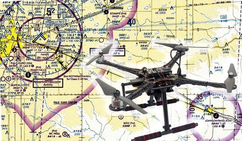
2 CIRCUIT CELLAR • MAY 2020 #358
Issue 358 May 2020 | ISSN 1528-0608
OUR NETWORK CIRCUIT CELLAR® (ISSN 1528-0608) is published monthly by:
KCK Media Corp.
PO Box 417, Chase City, VA 23924
Periodical rates paid at Chase City, VA, and additional offices.
One-year (12 issues) subscription rate US and possessions
$50, Canada $65, Foreign/ ROW $75. All subscription orders
payable in US funds only via Visa, MasterCard, international
postal money order, or check drawn on US bank.
SUBSCRIPTION MANAGEMENT
Online Account Management: circuitcellar.com/account
Renew | Change Address/E-mail | Check Status
SUPPORTING COMPANIES CUSTOMER SERVICE
E-mail: customerservice@circuitcellar.com
Advanced Assembly 1 Phone: 434.533.0246
Mail: Circuit Cellar, PO Box 417, Chase City, VA 23924
All Electronics Corp. 77
Postmaster: Send address changes to
Circuit Cellar, PO Box 417, Chase City, VA 23924
CCS, Inc. 77
NEW SUBSCRIPTIONS
easyOEM 49 circuitcellar.com/subscription
HuMANDATA, Ltd. 13 ADVERTISING
Contact: Hugh Heinsohn
IAR Systems, Inc. C3 Phone: 757-525-3677
Fax: 888-980-1303
Newhaven Display International, Inc. 11 E-mail: hheinsohn@circuitcellar.com
Advertising rates and terms available on request.
Pico Technology 21 NEW PRODUCTS
E-mail: editor@circuitcellar.com
Technologic Systems, Inc. C4, 77
HEAD OFFICE
University of Cincinnati 19 KCK Media Corp.
PO Box 417
Chase City, VA 23924
Wind River 41 Phone: 434-533-0246
COPYRIGHT NOTICE
NOT A SUPPORTING COMPANY YET?
Contact Hugh Heinsohn Entire contents copyright © 2020 by KCK Media Corp.
All rights reserved. Circuit Cellar is a registered trademark
(hugh@circuitcellar.com, Phone: 757-525-3677, Fax: 888-980-1303) of KCK Media Corp. Reproduction of this publication in
to reserve space in the next issue of Circuit Cellar. whole or in part without written consent from
KCK Media Corp. is prohibited.
THE TEAM
DISCLAIMER
PRESIDENT EDITOR-IN-CHIEF ADVERTISING COORDINATOR
KCK Media Corp. makes no warranties and assumes no
KC Prescott Jeff Child Nathaniel Black responsibility or liability of any kind for errors in these
programs or schematics or for the consequences of any such
CONTROLLER SENIOR ASSOCIATE EDITOR ADVERTISING SALES REP. errors printed in Circuit Cellar®. Furthermore, because of
Chuck Fellows Shannon Becker Hugh Heinsohn possible variation in the quality and condition of materials and
workmanship of reader-assembled projects, KCK Media Corp.
disclaims any responsibility for the safe and proper function
FOUNDER TECHNICAL COPY EDITOR PROJECT EDITORS
of reader-assembled projects based upon or from plans,
Steve Ciarcia Carol Bower Chris Coulston descriptions, or information published in Circuit Cellar®.
Ken Davidson
GR APHICS David Tweed The information provided in Circuit Cellar® by KCK Media
Corp. is for educational purposes. KCK Media Corp. makes
Grace Chen
no claims or warrants that readers have a right to build
things based upon these ideas under patent or other
relevant intellectual property law in their jurisdiction, or
that readers have a right to construct or operate any of
COLUMNISTS the devices described herein under the relevant patent or
other intellectual property law of the reader’s jurisdiction.
Jeff Bachiochi (From the Bench), Bob Japenga (Embedded in Thin Slices), The reader assumes any risk of infringement liability for
Robert Lacoste (The Darker Side), Brian Millier (Picking Up Mixed Signals), constructing or operating such devices.
and Colin O’Flynn (Embedded Systems Essentials) © KCK Media Corp. 2020 Printed in the United States
circuitcellar.com   3

      INPUT
        Voltage
                        Tech Community Steps Up to Battle COVID-19

O                n behalf of the Circuit Cellar staff, we
                 hope that you and your loved ones
                 remain safe and healthy during this
                 challenging time. Our team all work
remotely and we're committed to keep assembling the
quality magazine you've come to expect each month.
                                                                     Kinsa's thermometers are based on Nordic
                                                                 Semiconductor's nRF52810 SoC. Because Kinsa’s smart
                                                                 devices are battery-powered, they require an ultra low-
                                                                 power Bluetooth Low Energy solution, but one that also
                                                                 has enough on-board processing power and memory
                                                                 to essentially run the entire smart medical application
Hopefully we can keep inspiring you, provide some                from a single chip.
distraction and share some interesting project stories               The DIY community has also been engaging in ways
during this uncertain time.                                      to contribute their expertise to the COVID-19 battle.
    Shifting gears, I've been incredibly inspired by the roles   Embedded processor vendor Espressif Systems reports
the embedded community—from technology companies                 a story of an Indian engineer, Abhijit Mukherjee, that
to individuals—have played as they've stepped up in their        has come up with an Espressif ESP8266-based solution
own unique ways to battle the COVID-19 pandemic. These           for safe measurements of body temperature during
roles include large, generous efforts in resources and           the COVID-19 crisis. Abhijit says he “felt the urge to do
equipment, but also intriguing cases where embedded              something which could help” during the current global
technologies have been crucial in enabling solutions for         pandemic. By posting his project on hackster.io, he also
dealing with COVID-19 at many levels.                            wants to invite suggestions from other makers on how
    As I write this (in early April), Intel has just             to improve his solution.
announced it's pledging $50 million in a pandemic                    Baffled by the lack of reasonably-priced contactless
technology initiative to combat the coronavirus through          thermometers on the market, and prompted by the
accelerating access to technology at the point of patient        necessity to safely check from a distance the temperature
care, speeding scientific research and ensuring access to        of people he had to deal with in his personal and
online learning for students. Around $40 million will fund       professional, daily life, Abhijit says he built a completely
the Intel COVID-19 Response and Readiness and Online             autonomous and contactless, IR temperature-measuring
Learning initiative. Intel says that initiative will provide     device which can be mounted anywhere—an office
funding to accelerate customer and partner advances              door, an apartment entrance, or the on front gate of
in diagnosis, treatment and vaccine development,                 an apartment block. Abhijit’s gadget can track people’s
leveraging technologies such as artificial intelligence          temperature and post the results to any cloud or incoming
(AI), high-performance computing and edge-to-cloud               webhooks (a simple way to post messages from apps into
service delivery. Through the initiative, Intel will help        the Slack messaging app). We'll post a link to Abhijit's
healthcare and life sciences manufacturers increase              ESP8266-based, contactless, IR thermometer on Circuit
the availability of technology and solutions used by             Cellar's article materials webpage.
hospitals to diagnose and treat COVID-19.                            All of you please stay healthy and safe, but also as
    You may have heard of Kinsa Health in the news               connected and engaged as you can.
recently. Kinsa makes smart thermometers that
connect via Bluetooth to the Kinsa App. The app can not
only keep a log of readings, but also provide users with
a range of benefits including guidance on when to seek
further medical advice, provide medication reminders
and so on. For several years, anonymous data from
the Kinsa App has enabled Kinsa Health to produce a
temperature heat map of the US (that Kinsa calls its
US Health Weather Map) that could be used to identify
potential COVID-19 hotspots much more quickly and
help government agencies and healthcare organizations
in their on-going battle against the virus.

                                                                 Jeff Child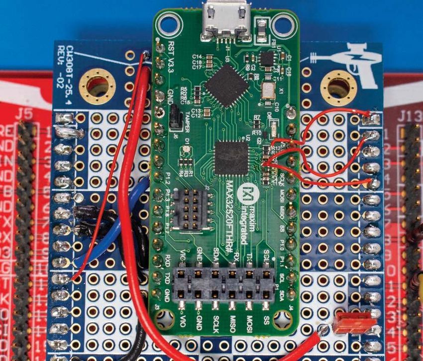
4   CIRCUIT CELLAR • MAY 2020 #358

              COLUMNS

                       TECHNOLOGY SPOTLIGHT

    50 Embedded  Software Tools
       Bulk Up on Security
                       Connected System Concerns
                                                       By Jeff Child

                       DATASHEET

    54 Mini-ITX and Pico-ITX SBCs
                       Performance Platforms
                                                                       PG. 58
                                                       By Jeff Child

    58 Build a SoundFont MIDI
                       Picking Up Mixed Signals

                       Synthesizer
                       (Part 1) Using Teensy 4
                                                    By Brian Millier

    64 Broad Market Secure MCUs
                       Embedded System Essentials

                       Spotlight on the MAX32520
                                                   By Colin O’Flynn

    68 Upgrading the Weather Tree
                       From the Bench                                  PG. 64

                       With I2C Interfacing
                                                   By Jeff Bachiochi

                       TECH THE FUTURE

    79 Securing Linux-Based Systems
                       The Future of Linux Security

                       in 4 Steps
                                                    By Glenn Seiler

    76 : PRODUCT NEWS
    78 : TEST YOUR EQ

                                                                       PG. 68
circuitcellar.com 5
FEATURES
6 Proximity Food Delivery
Notifier
Bluetooth-Based Design
By Kenichi Kato
14 Intro to Ardupilot and PX4
(Part 2) Building the Drone
By Raul Alvarez-Torrico
PG. 6
22 Build an Automated Pest
Deterrent System
Using Raspberry Pi
By Cole Gamborski, Cameron Phillips and Simon Fowler
28 Creative Mechanical Ideas
for Embedded Systems
Professional Style Projects
By Wolfgang Matthes
36 Modernizing the Accuracy of
an Antique Clock
PG. 14 Using a PSoC4 MCU
By Aubrey Kagan
SPECIAL FEATURE
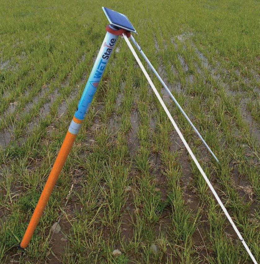
42 Smart Agriculture Designs
Tap IoT Technologies
The Internet of Growing Things
By Jeff Child
@editor_cc
@circuitcellar circuitcellar
PG. 22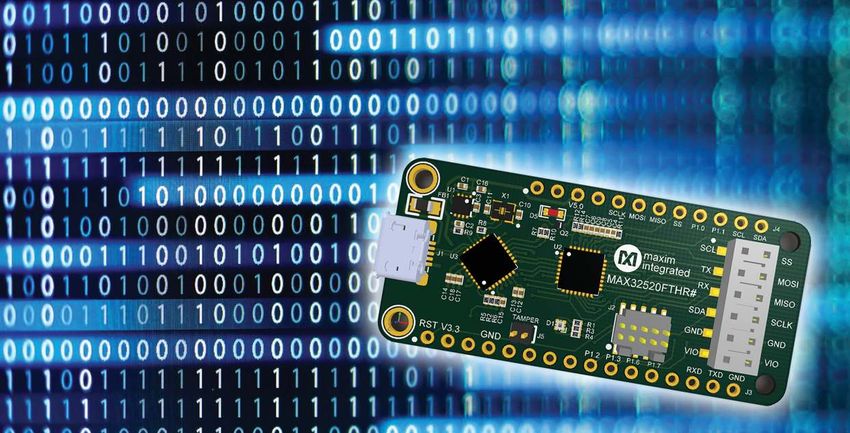
6    CIRCUIT CELLAR • MAY 2020 #358

           Proximity Food
           Delivery Notifier
           Bluetooth-Based Design
FEATURES

           Home delivery of meals is very popular
           these days, and technology is only fueling
           that trend. But nobody wants food that’s
           gone cold because the delivery guy
           forgot to ring the doorbell. Like any good
           engineer, Kenichi built a sensor-based
           solution designed to wirelessly alert him
           via Bluetooth that the food has arrived
           on his doorstep.

           By
           Kenichi Kato

                                                    I       t's well known that Singapore is a food
                                                            paradise. I couldn’t agree more. But, it's
                                                            really not healthy to go out to eat every
                                                            day. Homecooked food is always the best,
                                                     but it can be extremely time consuming and not
                                                     so economical for a household of two like ours.
                                                                                                         during the weekdays. It's very economical and
                                                                                                         convenient and best of all, you can get food
                                                                                                         made for health-conscious customers.
                                                                                                             For us, the delivery time varies between
                                                                                                         3 PM and 7 PM. The problem is that delivery
                                                                                                         guy—due to his tight delivery schedule—often
                                                     With that in mind, so, we order "Tingkat"—          forgets to press the doorbell to alert us that the
                                                     home delivered food services—for our dinner         food is delivered. Sometimes, the food would
                                                                                                         be at the gate for more than a few hours. If
                                                                                                         not kept at a certain temperature, some foods
                                                                                                         can spoil easily—or a mischievous neighbor
                                                                                                         might just take it and have a free meal. I'm
                                                                                                         not saying that from our experience. We have
                                                                                                         nice neighbors! So, as any engineer would do,
                                                                                                         all this inspired me to create a solution. This
                                                                                                         article describes my Proximity Food Delivery
                                                                                                         Notifier system for solving this problem.

                                                                                                         FOOD ALERT
                                                                                                             The basic idea is to have a system to alert
                                                                                                         us that our food has been delivered at our
                                                                                                         doorstep. The overall design (Figure 1) shows
                                                                                                         a fixed location with a hook for placing the
                                                                                                         food where a sensor will also be planted, a
                                                                                                         controller that will read and wirelessly relay
                                                                                                         that information to a receiver. In this case,
                                                                                                         a smartphone would work just fine. So, for
                                                                                                         the specific location, a sensor detects the
                                                                                                         existence of the food based on the proximity
                                                                                                         of an object. In this project, I have chosen
           FIGURE 1                                                                                      an ultrasonic sensor as the proximity sensor
           This shows the overall design with the major sub-systems.                                     because it provides some accuracy on the
circuitcellar.com 7
distance from the object. I found the Parallax FIGURE 2
PING sensor (Figure 2) to be particularly easy Parallax’s PING ultrasonic sensor.
to implement because it provides information
on distance in both centimeters and inches.
Since I am using the Parallax Propeller for
this project, the code that comes with the
FEATURES
PING sensor is particularly helpful—providing
distance readings in centimeters and inches.
I selected Bluetooth as the wireless
protocol for this project. That's mainly
because the Bluetooth module I had on hand
is a Class 2 and the distance between the
delivered food and the receiver is also less
FIGURE 3
than 10 meters. I used an HC-05 module
Wavesen’s Bluetooth Class 2 module.
(Figure 3) because I have quite a stock of
these modules from my previous projects that
I did back in 2013. Moreover, this module is
very easy to implement because the PCB has
castellation pads. These pads make it easy to
either mount it as a SMT device on a PCB or
insert to breadboard after soldering in the
headers. Besides all that, this module is also
very versatile in that configuration to it are all
via the AT commands in a UART terminal. The The Figure 4a schematic shows the basic
module is also very widely used, so there are components for the microcontroller, which
many articles and websites providing useful includes the EEPROM and 5MHz crystal plus
information about its configuration. And, the connectors, while the Figure 4b schematic
best part is you can get it for less than $5 (US). shows the HC-05 Bluetooth module and an
As for the controller, the location for optional tactile switch for the microcontroller
holding the delivered Tingkat food is very as user input. Finally, schematic Figure 4c is
small and narrow, so I designed a small PCB the power circuit with LDOs for 5V and 3.3V.
that houses all the necessary components and Figure 5 shows the top and bottom image of
the Parallax Propeller chip. This is the Propeller the PCB. Figure 6 shows 3D model of the top
version 1 since the Propeller version 2 and bottom enclosure for the PCB. I used a 3D
was just being released as of this writing. printer to print out the enclosures and hold
8,
, ,
, , .
56+8
(
, '22
, , ,,
, ( , 5 5 ),/
,( 7 , , , ,
,7 , ,, ,
. "
, , , . ,
; ",
,, ,, , ,,, , 7
+0 "
,, , ,( ,, (
+" .++
,,( , ,7 ,,
(0,
((
(
(
(,
(
7
(
.
.++
,
,
, ,,7 ,( , ,7
( 7
,, , ,
,, 57 ,7 , ,(
, 7 , (
( ,, , (
. 34
, - "
.++ -9
7 ,, 7
06 196 -:
, 56+8 -,
1
56+ .++
, 7 ,
.
, ,
, , ( ,,
,
,, ,, ,
,
.
.++
,
,
,(
,
,7
,
,
,,
5.
,
,
,
,(
,
,7
,
,
,
8
,
, ,
,,,
,,
,, ,,
+ ( 7
,,( ,, FIGURE 4A
,, ,,
,,7
),/ ),/ ),/ ),/ Shown here are the basic components
for the microcontroller which includes
the EEPROM and 5MHz crystal plus
connectors.
8 CIRCUIT CELLAR • MAY 2020 #358
them together with 4 bolts and nuts. Figure 7 mind, there is a simple power circuit to step-
shows the final working unit that has been in down the input voltage of 9V. Because the
use since July 2016. It hasn't failed since. input voltage is rather low, LDOs (low dropout
The power requirements are 5V for the regulators) will work just fine providing low
PING sensor and 3.3V for the other onboard inefficiencies. However, you can use any
components and peripherals. With that in Propeller-based boards available on the
FEATURES
Parallax website, for example the Propeller
QuickStart or the Propeller Project Board
*+
+ 2
.
USB. I personally prefer the latter because
+ it provides ample prototyping space for
+ 2
mounting other components.
+ ,- On the receiver part, I used an Android
phone. Using the MIT App Inventor 2 tool
+9 2+ [1], which is free, I could rapidly develop an
+
16 :8++ app using the code blocks. Figure 8 shows
2 26 :8+ 2 34+
+
1* :8=
+
the Designer view of the MIT App Inventor 2
+ 21* :8 +
73& :8
0 and Figure 9 shows the Blocks Editor View. If
9 =
78 1 :89
you are new to MIT App Inventor, I encourage
7:; :8 1 +
=
7*7@
*>7?
app, as I like to keep it simple, I only used less
8*:
:*8
+/ (+/
0;
*>
3&
;
than 10 components. So, that’s all on the main
building blocks for this system. Now, let me go
+
+
+9
+
+=
+
+
deeper into each of the sub-system.
CONTROLLER
FIGURE 4B The programming language I used for
Shown here are the HC-05 Bluetooth module and an optional tactile switch for the microcontroller as user the controller was SPIN by Parallax for the
input.
Propeller 1 microcontroller. My code for this
FIGURE 4C
This is the power circuit with LDOs for 2 2
2
+ *3+
5V and 3.3V. 6+
+
+
5-
.0 8 9 .0 8 9
+0 10 - 10 + +
,4
#2
% , -. , -
. 1
+/ +/ +/
'5
&
$'
&
*)
!"#$%&
$'
(
)#*)
++%
'7
&
$'
FIGURE 5 FIGURE 6
This is the top (left) and bottom (right) image of the PCB from my CAD. This is the 3D model of the top (red) and bottom (blue) enclosures for the PCB. I used a 3D printer
to print
!"out the enclosures
#$ and hold them with
%&
$' (4 )#*)
bolts and nuts.
++%circuitcellar.com 9
project available on the Circuit Cellar article normal .spin file, there are five major sections:
code and files download webpage. Even though CON (Constant blocks), OBJ (Object blocks),
the “.spin” files are in a plain-text format, you VAR (Variable blocks), PUB (Public method
will need a compiler to compile into bytecode. blocks) and PRI (Private method blocks). For
I usually use the Propeller Tools for Windows this project, I don’t need the VAR because I
by Parallax. You can download and install the only needed the local variables within the PUB
FEATURES
Propeller Tools software for Windows from Main section. In the CON section, I declared the
Parallax’s website [2]. If you are not using required _clkmode which is the application-
a Microsoft Windows machine, you can also defined clock mode and since the board uses
download PropellerIDE, which runs on Linux/ a standard 5MHz crystal, the _xinfreq
Ubuntu, OS X and Windows. which is the application-defined external clock
The main file is #TingkatR1v1.spin. In a frequency was declared as 5_000_000.
FIGURE 7 FIGURE 8
This is the final working unit that has been in use since July Designer view of MIT App Inventor 2
2016. It has not failed since.
t FIGURE 9
Blocks Editor view of MIT App Inventor 210 CIRCUIT CELLAR • MAY 2020 #358
CON
_clkmode = xtal1 + pll16x
_xinfreq = 5_000_000
Next, we declare the I/O pin from the ultrasonic sensor’s connection to the Propeller. The connection is on pin 3.
FEATURES
_ping = 3
The final declaration would be for the Bluetooth module’s connection to the Propeller.
BTComm _Tx = 26 ‘’(Transmit from Bluetooth Module)
BTComm _Rx = 25 ‘’(Receive from Bluetooth Module)
BTComm _Baud = 19_200 ‘’Baudrate
The next section, OBJ, we will need two object files. These are also downloadable from Parallax’s OBEX website [3]. Most of
these objects were written by members of the Parallax community. I, myself, have contributed a few of them.
OBJ
Ultra : “Ping.spin” ‘’Connects to ultrasonic sensor
BTM : “FullDuplexSerialExt.spin” ‘’Using UART to communicate with HC-05
The PUB will hold the Main section which are the main codes. Notice the “| scannedObj”? That is the local 4-bytes variable
within the Main section.
PUB Main | scannedObj
BTM.Start(BTComm _Tx, BTComm _Rx, 0, BTComm _Baud) ‘’Initialises the Bluetooth
Pause(500) ‘’Pause for 500 ms
Repeat
scannedObj := Ultra.Centimeters(_ping) ‘’Get the measurement
BTM.Dec(scannedObj) ‘’Sends out to the Bluetooth module to receiver
Pause(2200) ‘’Pause for 2.2 secs
Finally, for the PRI section I usually like to add this function to most my projects because it converts the system clock into
milliseconds which becomes very convenient to use throughout the code. It was initially written by a member of the Parallax
community, Jon McPhalen.
Depending on your personal needs, you can make the necessary changes or add additional sensors for other locations. Say
if you have 2 ultrasonic sensors, you will then declare two objects like this:
CON
_ping1 = 3 ‘’Assigning sensor 1’s I/O pin to pin 3 of MCU
_ping2 = 4 ‘’Assigning sensor 2’s I/O pin to pin 4 of MCU
OBJ
Ultra[2] : “Ping.spin”
And in your PUB Main section, use them like this:
scannedObj1 := Ultra[0].Centimeters(_ping1)
scannedObj2 := Ultra[1].Centimeters(_ping2)
RECEIVER
ABOUT THE AUTHOR Now onto the receiver unit. I used Google Chrome as my default browser.
Kenichi (ken@kenichikato.com) currently Navigating to appinventor.mit.edu [1], you will see the home page of MIT App
works as the Head of Research & Inventor 2. Click on the “Create App!” button and it will direct you to the login
Development (Software) in a Singapore and account creation page. For me, I logged in using my Google account. You
local SME. Previously, he worked as an will need to create one if you do not have a Google account. Next, it will direct
e d u c a t o r a n d e n g i n e e r i n S i n g a p o re you to your project listings. If you are new to MIT App Inventor, you won’t see
Institute of Technology. His passion has any project listings yet. So, you could either create a new project or load my
been in software development since the late “.aia” project file and modify from there. Just to give you a brief introduction
80s with designing embedded systems and to MIT App Inventor, I will show you how to add components from the Palette.
robotics (humanoids) from the mid-2000s. In the Designer interface, you will be able to drag and drop the types
of user interface, layout, sensors and so forth onto the main screen calledcircuitcellar.com 11
Screen1 by default. This is what you will see
when you first launch the app on your phone.
You will be able to add multiple screens
depending on your needs. First, I selected
the Bluetooth client component from the
FEATURES
FIGURE 11
If you already have your device paired,
upon clicking the button, the app will
bring up the list of devices as shown
in Figure 11. Since I was using a
FIGURE 10 Bluetooth module from my previous
Once you launch the app as here, the first thing is to connect project, it was renamed as "TellMe"
the app to your Bluetooth device. There is a button “Connect instead of the default HC-05. (Other
to Tingkat Checker” that allows the app to bring up the list of devices have been blurred out here for
Bluetooth devices already paired with your phone. privacy sake).
Designing with Passion. Engineering with Precision.
Working together to design
the ideal display for your
application. Let’s get started
on your next project.
nhdisplay.com/cc5m12 CIRCUIT CELLAR • MAY 2020 #358
FIGURE 12 Connectivity Palette and dropped it onto the
When I tap on my Bluetooth device, Viewer. This is needed to connect to our HC-05
the button will be changed to
Bluetooth module on the controller.
“Connected” as shown here. Notice the
Next is the Text-to-Speech component.
text box at the bottom that initially
showed “Debug Log Box” has changed
This will inform us that the “food is here” via
to “373”. This “373” is the reading that the text-to-speech feature. I have added two
FEATURES
was received from the controller which Clock components which are timers. Clock1 is
is the 373 cm between the ultrasonic used to check if there are any data received in
sensor and the object. the Bluetooth client in the app. Clock2 is used
to define the duration to announce “Food is
here” when food was placed in the assigned
location. Next, I'll show you some screen
captures as the app is launched and explain
FIGURE 13 the process flow. Hopefully this will help you
The “373” reading that was received from the understand the code in the Blocks Editor.
controller means that there is 373cm. The
datasheet for the ultrasonic sensor states that
USING THE APP
the non-contact distance measurements are
Once you launch the app as shown in
from about 2cm (0.8") to 3 meters (3.3 yards).
That means there is nothing being placed on
Figure 10, the first thing is to connect the app
the hook shown here. to your Bluetooth device. There is a button
that is labelled “Connect to Tingkat Checker.”
This allows the app to bring up the list of
Bluetooth devices already paired with your
phone. Therefore, you will need
to ensure that the Bluetooth
module (HC-05) is already
paired with your phone before
it can be listed. If you already
have paired, upon clicking the
button, it will bring up the list of
devices as shown in Figure 11.
Since I was using a Bluetooth
module from my previous
project, it was renamed as
TellMe instead of the default
HC-05.
If you are going to use the
HC-05 module, please look
at its datasheet under “Set/
inquire device’s name” section
for this feature. Back to the
list of Bluetooth devices, once I
tapped on my Bluetooth device,
the button will be changed
to “Connected” as shown in
Figure 12. You will notice the
text box at the bottom that
initially showed “Debug Log
Box” has changed to “373.” This
“373” is the reading that was
received from the controller
which means there is 373cm
between the ultrasonic sensor
and the object.
Since the datasheet for
the ultrasonic sensor states
that the non-contact distance
measurements are from about
2cm (0.8") to 3 meters (3.3
yards), that means there is
FIGURE 14
When food is placed on the hook as shown here, the value in the
nothing being placed on the
app shows 5cm (see Figure 15). hook (Figure 13). However,circuitcellar.com 13
FPGA Boards from JAPAN
SAVING COST=TIME with readily available FPGA boards
the debug textbox was just to show the actual readings
Basic and simple features, single power supply operation
coming from the controller since the retrieval was timed at
every 1,000ms (1 second) by Clock1. Clock2 is assigned to Free download technical documents before purchasing
activate every 10,000 ms (10 seconds). It will first transfer
the value received from the controller and place it into the
TextBox1 then perform a verification to see if it is below
L ACM-031
INTEMAX 10 U169 FPGA board
FEATURES
the value 10 (meaning 10cm). However, when food is placed
on the hook as shown in Figure 14, the value shows 5cm
5V I/O support
as shown in Figure 15. This will then trigger the Text-to-
Speech component to say “Food is here” every 10 seconds
until someone removes the food from the hook!
On the Circuit Cellar article code and files webpage, I
have provided the code, 3D models for the enclosure in .STL
format and the Gerber files with the bills of materials if you
wish to produce the same PCB as mine. My device has been
in operation since July 2016 and it is still in good working
condition today. By using this simple concept, you can also
create your own proximity sensors around your house as
home surveillance or a door response system to do
something when someone is at your door. The possibilities
are endless. So, create your very own mobile notification
system today!
SIZE : 3.386" x 2.126" (86 x 54 mm)
ACM-031 is an FPGA board with
Intel high-performance FPGA MAX 10.
It's compact and very simple.
5V single power supply operation.
INX XCM-026
XILSpartan-7 FGGA484 FPGA board
5V I/O support
FIGURE 15
The "5" appearing on the app means that the food has arrived because it is 5 cm
from the sensor. This triggers the Text-to-Speech component to say “Food is here”
every 10 seconds until someone removes the food from the hook!
SIZE : 3.386" x 2.126" (86 x 54 mm)
For detailed article references and additional resources
XCM-026 is an FPGA board with
go to: Xilinx high-performance FPGA Spartan-7.
www.circuitcellar.com/article-materials It's compact and very simple.
References [1] and [3] as marked in the article can be 5V single power supply operation.
found there.
See all our products, A/D D/A conversion board,
RESOURCES boards with USB chip from FTDI and accessories at :
Parallax Inc. | www.parallax.com
Guangzhou HC Information Technology | www.wavesen.com
www2.hdl.co.jp/CC20C14 CIRCUIT CELLAR • MAY 2020 #358
Intro to Ardupilot and PX4 (Part 2)
Building the Drone
FEATURES
In Part 1 of this article series, Raul gave
an overview of a drone design using open-
source autopilot platforms. Here in Part 2,
he goes step by step and describes how to
build, configure and test a DIY quadrotor
drone with the PX4 platform.
By
Raul Alvarez-Torrico
I n Part 1 of this article series last month,
I discussed the general architecture of
a DIY multirotor drone and its main
hardware and software components.
I also gave a general introduction to the
Ardupilot and PX4 platforms, discussing
Figure 1 shows an amazing wiring chart
made by Jethro Hazelhurst for the Ardupilot
website [1]. To see greater detail, you can
check the original version by using the link
in the figure caption. Analyze the picture in
detail. It will be instructive if you have never
some examples of supported flight controller built a quadcopter before.
hardware and vehicle types, as well as The build process for a typical quadrotor—
available ground control software from both like the one I will show as an example in
platforms. Additionally, I provided a general this article—is practically the same for
introduction to the MAVLink protocol used to both the PX4 and Ardupilot platforms. For
communicate vehicles with ground control this summary, I will use the PX4 platform
stations in both platforms. In this second to explain the process. So, what steps are
part, I will discuss the main steps involved generally involved in building, configuring
in the building and configuration of a DIY and flying a quadcopter? I divide the process
quadrotor with the PX4 platform. It will not in four sections: 1) the hardware build; 2)
be a complete tutorial, but a review of the flight controller firmware programming and
most important steps involved. I will also give configuration; 3) Electronic Speed Controller
some tips that address potential problematic (ESC) calibration and pre-testing; and 4)
situations in the build process that are not flight test(s). Within each of those sections
always immediately obvious for beginners. are several steps. The following development
There are a lot of well documented assumes you are already familiar with the
tutorials out on the Internet. Consider this main parts used to build a multirotor. Please
article a summary of steps and important see Part 1 of this article series (Circuit Cellar
tips from my own experience, for beginners 357, April 2019) for more details.
who want to build their first quadrotor. At the So, here is one of the first tips I would give
end, I will also share additional tips on how to to anyone doing their first quadrotor build.
get started with autonomous flight by using
the MAVSDK library and MAVROS package. Tip #1: Never rush with any steps involved
Let’s see if, with this article, I can encourage in the process, always double-check everything
you to build your first quadcopter, and begin you do, and when in doubt, it is always better
to experiment with autonomous flight in the to do further research or ask anyone who’s
near future. more knowledgeable before proceeding.circuitcellar.com 15
THE HARDWARE BUILD that is detected by the accelerometer and
Step 1: The Frame. You’ll generally begin by gyroscope sensors in the flight controller.
building the frame. Frames come with a build This vibration is noise to the sensors, and can
instructions chart, or you can easily find one potentially affect the quadcopter’s stability.
on the Internet. Just don’t tighten the screws To minimize it, the flight controller can be
hard the first time. I highly recommend that installed on top of an anti-vibration mount,
FEATURES
you build the frame first, just to “present” it. as shown in Figure 3. I initially used rubber
bands to fix the flight controller to the anti-
Tip #2: For the first builds, it is better not vibration mount. In the final steps, it will be
to tighten the screws tightly at first, or to fixed with double-sided tape. Figure 4 shows
use threadlocker glue. Leave that for the final the motor layout for a "Quad X" configuration.
steps, after you are sure everything is correct Each motor has a given number, position and
and in place. rotation direction, so it is critical to connect
their corresponding ESC signal cables to the
Step 2: ESCs and brushless motors. For flight controller’s outputs in the given order.
connecting brushless motors, ESCs and
battery power supply lines, “banana” type Tip #4: The correct layout of all motors in
connectors are generally used. Although the the frame and connection of ESC input signal
S500 frame I used for my example build cables to correct output pins in the flight
(Figure 2) comes with a power distribution controller are of utmost importance. Failing
board “embedded” in the bottom plate of
the frame (which is just a double-sided PCB
used also as part of the frame structure),
for beginners I would recommend using a
separate power distribution board (PDB).
The reason for that is because it’s always
possible to mess up with the soldering needed
in the PDB. If this happens, it is cheaper and
easier to replace the separate PDB than to
replace the frame’s bottom plate. A typical
quadrotor of this size will consume around
15A in total while hovering in soft wind and
without payload. But the total current can
easily peak up to the double (if not more),
when carrying a payload, doing aggressive
maneuvers or flying in severe wind conditions.
Tip #3: All soldering related to the
propulsion system must be done carefully,
tidily and robustly. Those connection points
will carry high currents, so they must have
good electrical continuity. There must also
be the best isolation possible between the
positive and negative terminals.
As a safety measure, always check the
absence of electrical continuity between
every pair of "+" and "-" pads on the PDB. You
want to be sure there isn’t a short circuit in
it, due to the soldering process. Some ESCs,
brushless motors and power distribution
boards come with bullet connectors already
soldered. If not, you must solder them by
yourself. Figure 2 shows the ESCs, motors and
PDB embedded in my S500 frame, with all the
necessary connections. ESCs and cables will
later be secured to the frame by using plastic
zip ties.
Step 3: Flight controller, RC receiver
and GPS module. The spinning motors
and propellers in the quadrotor generate FIGURE 1
a certain amount of mechanical vibration Advanced Pixhawk quadcopter wiring chart [1]16 CIRCUIT CELLAR • MAY 2020 #358
to do this can make the quadcopter behave
erratically and ultimately crash.
For this build, I used a conventional
6-channel remote control (RC) system with
parallel analog PWM outputs. The Pixhawk
FEATURES
controller, however, just accepts serial PPM-
Sum or S.Bus input signals, which provide all
RC channel signals via a single serial digital
output. You can purchase an RC system with a
serial output receiver suitable for connecting
directly to the Pixhawk. Nevertheless, if you
have a system with parallel analog PWM
channels, low-cost parallel analog PWM-to-
digital serial converters, such as the one I
used for this build, are available.
The connection of the GPS and external
compass module is straightforward. The
module has two connectors. The wider one is
for the GPS receiver, and the narrow one for
the digital compass. The digital compass is
highly sensitive to magnetic interference. With
that in mind, a stand for the GPS module is
FIGURE 2 generally recommended to avoid interference
S500 frame with motors, ESCs and power distribution board from the rest of the electronics, especially
the power system. Figure 3 shows the flight
controller, RC receiver and GPS module with
its stand.
Step 4. Power module, battery and alarm.
The power module connected to the flight
controller and the PDB, as well as the LiPo
battery in place with its low voltage alarm, are
shown in Figure 5. The connection between
the flight controller, power module, battery
and propulsion system are illustrated clearly
in Figure 1, so go back to this at any time to
get a more detailed view of other connections.
To fly this quadcopter, I’m using a
5,000mAhour, 3S, 8C battery.
Tip #5: Improper use of LiPo batteries can
be extremely dangerous. Before charging,
connecting and using them, take the time to
thoroughly research their use and care. Many
resources on the Internet cover this topic in
detail.
Step 5. Telemetry module, gimbal and FPV
(first person view) transmitter. The telemetry
FIGURE 3 module must be connected to the TELEM1 port
Flight controller, RC receiver and GPS module
in the Pixhawk (Figure 1). The gimbal receives
power from the power distribution board. Mine
can work with LiPo batteries between 2S and
6S. Gimbals generally have a signal input to
ABOUT THE AUTHOR manually control the camera pitch angle. This
Raul Alvarez-Torrico has a BEng in electronics and is the founder of TecBolivia, input can be connected to any unused output in
a company offering services in physical computing and educational robotics the RC receiver, preferably one from a channel
in Bolivia. In his spare time, he likes to experiment with wireless sensor associated with a knob in the RC transmitter.
networks, robotics and artificial intelligence; he is also committed to publishing Once the gimbal is powered on, the camera
articles and video tutorials about embedded systems and programming in his should be automatically stabilized, and the
native language (Spanish), at their company’s website www.TecBolivia.com . pitch angle controlled with the associated
You may contact him at raul@tecbolivia.com. knob in the RC transmitter. Drone camerascircuitcellar.com 17
have a video signal output to be connected to FIGURE 4
the FPV video transmitter (powered also from "Quad X" configuration layout
the PDB). Usually, the FPV system is separated
CW CCW
from the drone system itself (Figure 1).
Step 6. Finishing the hardware build. I 3 1
usually connect the battery once at the end
FEATURES
of the hardware build, to be sure everything
is okay and nothing is getting hot due to a
short circuit, especially in the propulsion
system. Then, I proceed to tighten all screws
with threadlocker glue. I take them out one
by one from the frame and motors, apply
threadlocker and tighten them well in place
again. Threadlocker needs at least 24 hours to 2 4
properly cure. I use Loctite Threadlocker Blue, CCW CW
which is recommended for multirotor builds.
Tip #6: After your first flight and before
flying again, always check that the motor and
frame screws are still tight. Sometimes they
can loosen, because parts tend to settle further
with mechanical vibration, and the screws
would need to be tightened again. A loose
motor or frame part can make the quadcopter
vibrate too much and make it crash.
THE FIRMWARE
Although I’m using PX4 firmware for this
build example, the same quadrotor setup can
also be flashed with Ardupilot firmware by
following a similar set of steps, such as the
ones outlined as follows:
Step 1. Firmware flashing. It is really easy
to flash the firmware to the flight controller
by using ground control software. With
QGroundControl, you can do that by going
to the “Firmware” submenu located in the
“Vehicle Setup” menu (Figure 6) and following
the instructions given there. After flashing
the PX4 firmware, the frame type must be
configured in the “Airframe” submenu, under
the “Quadrotor x” option. I chose the "S500"
for this build (Figure 7).
Step 2. Sensor calibration. Next, from
the “Sensors” submenu, we calibrate the
compass, gyroscope and accelerometer,
and also level the horizon (Figure 8). Plenty
of guidelines are given in each step by
QGroundControl, itself.
Step 3. Radio setup. The radio calibration,
done in the “Radio” submenu (Figure 9),
ensures that the minimum and maximum
values for each RC channel are correctly set
in the flight controller. These values generally
vary from one RC transmitter to another.
Step 4. Flight modes configuration. In the
“Flight Modes” submenu (Figure 10), we can
configure up to six different flight modes. With
a 6-channel RC, I generally assign channel 5
for controlling the flight modes and channel 6 FIGURE 5
for the “Kill switch” function. The three most Power module, battery and low voltage alarm18 CIRCUIT CELLAR • MAY 2020 #358
useful flight modes I can recommend for Position is the preferred flight mode I
beginners are Altitude, Position and Return. recommend for beginners, especially for
Altitude automatically stabilizes the flying in windy conditions, because it uses the
quadcopter’s altitude by using the barometric barometric pressure sensor and also the GPS
pressure sensor (altimeter), but it doesn’t receiver for stabilizing the drone vertically
stabilize position in the horizontal plane. This and horizontally. But it doesn’t allow arming
FEATURES
is because this flight mode does not use the the motors and drone take-off without a good
GPS receiver. It requires you to stabilize the GPS fix, which you won’t get unless the GPS
quadcopter in the horizontal plane manually, receiver has good sky visibility.
which can be tricky for beginners, especially Return flight mode automatically returns
with strong winds. In this mode, the the drone to the home position, and is useful
quadcopter can be armed without the need if, for some reason, you lose control, and just
for GPS fix (useful for indoor motor testing). want the flight controller to take over and
land the drone by itself at the original take-
Tip #7: Never fly a quadcopter indoors off spot.
if you are a beginner, or if there are people Finally, it is also important to configure the
around. For your flight tests, always use “Kill switch” function to turn off the motors,
big, open fields without people, animals or especially when something goes awfully
obstacles around. wrong. For example, if the drone falls down to
the ground and the motors are still spinning,
even with the throttle stick at zero—or when
the drone is out of control and it is better to
switch it off (and crash it) before anything
worse happens.
Step 5. Power setup. In the “Power” submenu,
the flight controller’s battery power monitoring
function can be configured, so it can accurately
estimate the remaining power and flight time.
I generally just configure the “Number of cells”
parameter (“3S” for a 3S battery), and leave the
rest at their default values. At first, it's better
not to change the remaining parameters, until
you understand well how these parameters
affect the way the flight controller does the
aforementioned estimations.
Step 6. Failsafe actions. A “failsafe
FIGURE 6 action” is a predefined safety measure the
Vehicle setup menu and firmware flashing submenu quadcopter will take when some types of
failures occur. Examples of failures include
when the battery is at its minimum, when
the RC signal is lost, or when the data link
(telemetry) is lost. Available options for safety
measure configuration range from doing
nothing or giving a warning, to landing the
drone, returning it to home or hovering it in
place. Failsafe actions can be configured in
the “Safety” submenu. The default options
are also a good starting point.
ESC CALIBRATION &
PRE-TESTING
One last important step to take before the
first flight is ESC calibration (available from the
“Power” submenu). ESC calibration ensures
that all motors respond equally to the available
throttle range from the RC transmitter. This
is accomplished by teaching the ESCs to
recognize the minimum and maximum PWM
values for zero and full throttle.
FIGURE 7 Tip #8: Before attempting to take off for
Airframe setup the first time, check the rotation directioncircuitcellar.com 19
of all motors according to what’s specified
in the layout for the selected configuration. Tip #9: Always try to do your flight tests
Also check the correct propeller mounting. in the morning, when the wind is generally
Motors spinning in the wrong direction, or calmer than in the afternoon. Avoid flying
propellers incorrectly mounted will cause in relatively strong winds until you develop
erratic behavior, ranging from not being able good piloting skills. You can carry a pocket
FEATURES
to take off at all, to taking off and spinning anemometer to measure wind speed before
uncontrollably in the horizontal plane, or taking off.
taking off and turning upside down and
ultimately crash. The maximum wind speed in which a
quadrotor can be safely flown depends on the
If a motor spins in the wrong direction,
swap two of the three motor cables connected
to the ESC (any two of the three available) to
change the rotation direction. Also verify the
proper propeller mounting, with the upper
and lower cambers correctly positioned, and
the leading edge “cutting” right into the air, in
the right rotation direction.
FLIGHT TESTS
Until this point, for safety reasons, always
do all motor pre-tests without propellers, and
put the propellers on the motors just before
the first flight. Pick an open field with no
people, animals or obstacles around. If there
are natural or man-made obstacles (such as
tall trees, hills, buildings or towers), the GPS
receiver will take longer to get a fix, or worse FIGURE 8
yet, it will lose it intermittently during flight. Sensor calibration
LOOKING TO
ADVANCE
YOUR
CAREER?
Be a part of one of the
top Electrical Engineering
programs in country
and experience the
Bearcat Promise!
l(_t
University of
CINCINNATI I ONLINE ucengineer.o nline20 CIRCUIT CELLAR • MAY 2020 #358
Planner or APM Planner this time. These are
two ground-control software applications
from the Ardupilot ecosystem, and are similar
to QGroundControl.
MAVSDK AND MAVROS
FEATURES
MAVSDK is a MAVLink library from the
PX4 ecosystem that’s written in C++ and has
bindings to Python, Swift and Java. It also has
bindings to JavaScript, C# and Rust, though
still in “proof-of-concept” stage. MAVSDK
allows programmatic interaction with any
MAVLink-compatible vehicle, to get general
information from it, get telemetry data, send
action commands like arming, take off, land or
return to home, send commands to calibrate
sensors and send “low level” commands to
directly control vehicle movement [2]. For
instance, you can control position, velocity and
acceleration in three dimensions, to make the
drone change its states in response to decisions
made by some type of navigation algorithm.
FIGURE 9
quadrotor’s maximum speed. A good rule of In contrast, the MAVROS package (which
Radio setup
thumb is to set the maximum wind speed at is an ROS-to-MAVLink bridge, also from the
two-thirds or less of the quadrotor’s maximum PX4 ecosystem), allows the use of MAVLink
speed. For example, if the quadrotor’s top communication, to make it possible for any
speed is 80mph, two-thirds of that is about computer running the Robot Operating
53mph. This, according to the rule, will be System (ROS) middleware to communicate
the maximum recommended wind speed to with any vehicle or ground-control station
fly the quadcopter safely. Last but not least, software that uses the MAVLink protocol.
don’t forget to comply with all regulations in In summary, MAVSDK will allow you to
place for flying drones in your town, to avoid program a robotic drone, and MAVROS will
legal problems. allow you to do it straight away in an ROS
From a functional standpoint, PX4 environment, for a more modular, distributed,
and Ardupilot are not very different. scalable and professional approach. Ardupilot
The processes of flashing firmware and has also its own MAVLink library, called
configuring parameters are almost the same Dronekit, with available Python and Android
in both platforms. Besides, both are MAVLink- APIs. But apparently, not much work has
compatible and generally work well with the been done lately to provide support for other
same quadcopter setup, as long as the flight programming languages.
controller is compatible with both platforms. If you want to get started with autonomous
After you have flashed and configured your flight application development within the PX4
quadcopter with, say, PX4, and flown your ecosystem, I suggest you try MAVSDK and/or
drone for some time, you can try Ardupilot MAVROS in three stages.
if you wish. Every step described in the First, generally the easiest way to try
Firmware Flashing and Configuration section MAVSDK is to install the Python wrapper and
of this article will also apply, with minimum try some included examples with a "Software-
differences. You can even try to use Mission in-the-Loop" (SITL) simulator. The C++ version
installation can be a little more involved, in
some cases requiring building the library from
For detailed article references and additional resources go to:
source. MAVROS is useful only if you already
www.circuitcellar.com/article-materials
know how to use ROS. If you are new to ROS,
perhaps you should first learn ROS, before
References [1] through [2] as marked in the article can be found there
trying MAVROS. But you still can make your
drone fly autonomously by using MAVSDK. Both
RESOURCES MAVSDK and MAVROS can connect to vehicles
Ardupilot | https://ardupilot.org via serial port, UDP and TCP connections.
When working with a simulation, TCP/UDP
Dronecode | www.dronecode.org
connections will usually be the way to connect
mRobotics | https://mrobotics.io our software application with the simulator.
Second, once your code runs well on
PX4 Autopilot | https://px4.io simulation, you can try it on a real drone bycircuitcellar.com 21
opening the telemetry module serial port from
the application running on your development
computer or mobile device. In this case,
MAVSDK and MAVROS will communicate with
your drone by using the MAVLink connection
established via the telemetry modules.
FEATURES
Third and last, to make your drone truly
autonomous, you can upgrade your system
by adding a companion computer (Raspberry
Pi, Odroid, Jetson Nano or others) to your
quadcopter setup. The companion computer
can be connected directly to the TELEM2 serial
port of the flight controller to run the MAVSDK/
MAVROS code that controls the vehicle,
along with some other code interfacing with
additional sensors and actuators especially
suited for your application.
CONCLUSION
I hope the information presented in this it, but that’s the normal learning process for FIGURE 10
two-part article series gave you a general anyone. Still, it is a lot of fun! Most excitingly, Flight modes configuration
perspective about the PX4 and Ardupilot once you get a good grasp of what’s involved
platforms, and what is involved in building in building and configuring a quadcopter
a quadcopter for aerial photography, or properly, you can begin to experiment with
perhaps more interesting, for experimenting autonomous drone applications.
with autonomous flight. If you have never In a future follow-up to this article, I will
built a quadcopter before, I really encourage cover in more detail—and with a concrete
you to do it and experiment. example—how to use the MAVSDK library to
I’m not going to lie, you’ll crash many times develop code for autonomous drones using
while learning to pilot it and experimenting with SITL simulation. Until the next time!
• 8-bit to 12-bit FlexRes® ADCs
• 8 x 500 MHz analog channels
• Up to 16 x 1 Gb/s digital channels
• Dual 5 GS/s ADCs
The NEW PicoScope ®
• 4 GS capture memory (up to 2 GS per trace)
6000E Series •
•
50 MHz 200 MS/s 14-bit AWG
300 000 waveforms per second update rate
• Free PicoScope 6 and PicoSDK software
• Serial decoding and mask limit testing
• High-resolution timestamping of waveforms
• Over ten million DeepMeasure™ results per
acquisition
• Advanced triggers: pulse width, runt pulse,
A smarter scope for faster debug windowed, logic and dropout
Visit www.picotech.com/A540 to discover MORE
Email: sales@picotech.com. Errors and omissions excepted. Please contact Pico Technology for the latest prices before ordering.22 CIRCUIT CELLAR • MAY 2020 #358
Build an Automated Pest
Deterrent System
Using Raspberry Pi
FEATURES
Garden pests are a threat to your
flowers, vegetables and fruit. Learn
how these Camosun College students
designed an automated pest deterrent
system that uses an ML-trained
Raspberry Pi to detect and identify
pests, and Bluetooth to communicate
to its user. Their prototype base unit
displays relevant information gathered
by two field units.
By
Cole Gamborski, Cameron Phillips and Simon Fowler
W hat inspired us to choose
this project? It was a
conversation Simon had with
his father last summer, while
sitting and having lunch. His father told him
how the deer had come again in the night
security. Knowing that your target is 40+
feet away and approaching allows the system
plenty of time to exit sleep mode and enact
its security measures. After researching the
passive infrared sensor (PIR) market, we
found the best choice to get this job done
and eaten the flowers off all 28 of his tomato was the Panasonic EKMB1306112K. This
plants. His father said, “Son, could you invent high-precision PIR, made of top-of-the-
something to keep these pesky deer out of my line materials from a trusted manufacturer,
garden?” Simon knew that his dad was not boasts one of the densest detection zones
alone with this issue. Being a farmer himself, available.
he had experienced just how much damage It’s able to achieve a 17-meter detection
deer can do. range, with as little as a 4°C temperature
When considering crop security and pest difference between the detected target and
deterrence, the current market for the average ambient temperature. This means that a
homeowner is oversaturated with inefficient, single node could cover the average garden
ineffective products. By combining machine space of a home, or, if used close to the
learning (ML) with high-precision, passive perimeter of the property, the node could
infrared sensors (PIRs) and Bluetooth Low- see and begin deterring the target before it
Energy (BLE), we created a more sophisticated reaches your garden.
deterrent system that touched on each group There is one downside to using PIRs—false
member’s technological area of interest. triggering. We have gone to great lengths in
Based on our project scope and the design to eliminate any possibility of false
requirements, we divided our product into a triggering. To achieve this, we started with
four-phase system: Detection, Distinguishing, stacked PIRs. These PIRs have a 60-degree
Deterrence and Disclosure. horizontal viewing angle. We used two PIRs
for each angle of approach—one above the
DETECTION other. To explain how this helps prevent false
Reliable and continuous scouting of your triggering, let’s take a common example: An
property is critical for garden and home outdoor security system.circuitcellar.com 23
You’ve got your motion-triggered sensor If you had seen this dog only from the front
set up outside, and have left it overnight to at its eye level, is there any way you could say
watch over things. Then, unbeknownst to you, with confidence what it might look like from
a moth or another photoactive bug lands on the side? Or from behind? For the AI to be
your sensor, causing your sensor to trigger truly effective at recognition, it needs images
constantly. You wake up the next day to find in different resolutions, lighting, perspectives
FEATURES
a night-long recording of nothing! What a and views.
waste of time and energy! By stacking two On our third training attempt, we used
PIRs and requiring both to be triggered at more than 300 images per category, making
once, we effectively reduce the likelihood of certain to use many different elements to help
false triggering. We wondered if maybe this flex our AI’s brain muscle. However, gathering
proactive design were not enough? This led us and manipulating 2,500 pictures is not easy,
to the next phase of our system. and it consumes time. We used websites such
as Unsplash and Pexels as sources of free
DISTINGUISHING images. After finishing the retraining, we
Let’s return to the moth example. You now resumed testing and saw accuracies greater
have moths on both of your PIRs, causing than 90% in some categories. It was a good
your alarm to run all night. How do you day at the office.
prevent false triggering in this situation?
Machine learning comes to the rescue by DETERRENCE
enabling the system to detect, recognize and We felt confident at this point to move
act judiciously instead of blindly. forward with the Deterrence phase of the
Software: We had two initial contenders system. Because we intended to use sound
for our product’s “brain”: OpenCV and as a deterrent, we researched how sound is
Tensorflow. We opted to use TensorFlow, perceived by different species. The average
because of its larger documentation base, human hearing range is 20Hz to 20kHz, and
its readily available tutorials, and—most most middle-aged humans can only hear in
importantly—because it is optimized for IoT the 15kHz range. While human hearing is
and mobile applications. The latter makes it limited to sounds below 20kHz, other species
great for the Raspberry Pi family, which was are capable of hearing in the ultrasonic
important because we planned on using the range (frequencies greater than 20kHz). For
Raspberry Pi 3B. However, TensorFlow had example, dogs, deer and raccoons can hear
its own challenges. During install, some of its up to 40kHz, and cats can hear up to 80kHz.
dependencies required updating. And since This meant that we needed a large, 10kHz
we were using Raspbian Lite OS, we had to audible range that would not wake you or
install these dependencies one at a time—at your neighbor if an alarm went off at night.
times having to revert applications to older The simplest way to guarantee a sound will
versions. remain at a specified frequency is to use pure
Training: Once we were able to run the tones—waveforms such as sine or square
basic tutorial example, the next step was waves. If you don’t know what a pure tone is
to check the trained processor's accuracy. there are several free pure-tone generators
Unfortunately, Google’s model was too global available on the Internet. Simply put, they are
for our needs—it identified a raccoon as a waveforms such as sine or square waves.
red panda. We completed the next tutorial of Pure Tones and Man’s Best Friend: While
retraining the processor for our own needs. pure tones make an effective deterrence
This meant creating categorized folders option for urban settings, we thought that
(cougar, deer, raccoon, cat, dog, human, rural options could use a more creative touch.
tractor and tree), and telling the processor After reading several articles on predatory
where to locate them. vocalizations and how they are used to deter
After our first retraining, we realized that urban pests, we learned that the pests had one
the Raspberry Pi 3B (Pi) was not ideal for definitive predator in common: Dogs. Because
the processor-intensive task. We decided to there are so few cougars and bears in urban
do all future training on a desktop computer, areas, pests have few, if any, encounters with
and then copy the image over to our Pi. After them. However, the pests are more than likely
retraining, we tested our model’s accuracy and to have several run-ins with dogs.
found it to be lacking. Results were between One of us (Simon) has 50-150 chickens on
60% and 76% accurate, using roughly 100 his farm at any given time. If they are not
photos per category. We learned that you need in their coop at night, raccoons will come to
at least 300 photos for consistent accuracy. hunt them. Generally, the raccoons aren’t
In addition to that, you need your photos afraid when he tries to chase them off. But
to portray different perspectives of the object. if his Labrador retriever gets out there and
Consider the appearance of your favorite dog. starts barking, they immediately scatter andYou can also read