The Data Acquisition System for the DarkSide-20k Detector - WNPPC Virtual Conference Ashlea Kemp - Queen's University - 11th February 2021
←
→
Page content transcription
If your browser does not render page correctly, please read the page content below
The Data Acquisition System for
the DarkSide-20k Detector
WNPPC Virtual Conference
Ashlea Kemp - Queen’s University - 11th February 2021

                               1
DarkSide-20k
Physics Reach
‣ Experiment designed to observe low energy nuclear recoils induced by WIMP dark matter-nucleus elastic scattering
‣ Large target mass, ultra-low background radioactivity & efficient background rejection/veto systems key to unlocking further sensitivity
  to WIMPs

                                                                                              The further down these lines
                                                                                             go, the more parameter space
                                                                                             we exclude and the closer we
                                                                                              come to finding dark matter!

    Ashlea Kemp                                              Queen’s University                                       11th February 2021
                                                                     2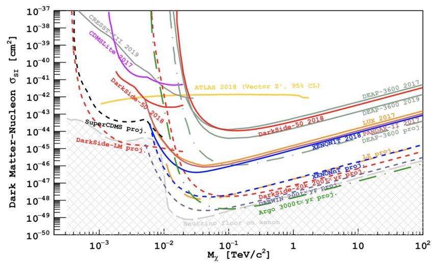
DarkSide-20k: Introduction                                                                   Cryostat
Detector Overview
                                                                                                            Veto detector
‣ Dual-phase liquid argon time projection chamber (LAr TPC) containing
  55 tonnes (20 t fiducial) of low-radioactivity underground argon (UAr)
                                                                                h = 10.8 m
   ➡ Particle interactions in Ar generate scintillation light via excitation
     and ionisation of argon atoms

   ➡ Scintillation light collected by Silicon Photomultiplier (SiPM)                                              SiPM array
     devices arranged on top/bottom of TPC vessel

   ➡ Scintillation “S1” signals used to discriminate between nuclear and
     electronic recoils using pulse-shape discrimination (PSD)
                                                                                                                  TPC vessel
   ➡ Uniform electric field applied across TPC so that ionised electrons
    that do not recombine are drifted to top of TPC vessel towards gas
    pocket; in GAr phase extracted electrons produce secondary
    scintillation photons through electroluminescence generating a
    secondary “S2” signal

   ➡ S2 signal measured by the SiPM arrays Δt after S1 signal
‣ TPC surrounded by veto detector
   ➡ Gadolinium-loaded plastic sheet for neutron captures

    Ashlea Kemp                                                    Queen’s University                   11th February 2021
                                                                           3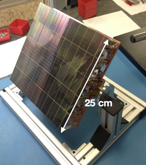
DarkSide-20k: Introduction                                                                                                   24 SiPMs/PDM

Silicon Photomultipliers (SiPMs)
‣ SiPMs are extremely sensitive, single-photon solid-state
  photodetectors
                                                                                                  25 PDMs/
‣ Compared to traditional photomultiplier tubes (PMTs) typically                                  motherboard
  employed in direct detection experiments, SiPMs…

   ➡ May have a lower radioactivity
   ➡ Have a significantly better single photon resolution
   ➡ Have a higher photon detection efficiency (> 40%)
‣ Photodetector modules (PDMs) each comprised of 24 SiPMs
‣ Each motherboard comprised of 25 PDMs
‣ Dark count rate (DCR) of < 250 Hz/PDM

                                                                           Typical single channel energy response (superseeded version of the FBK SiPM matrix): http://
                                                                            www-kam2.icrr.u-tokyo.ac.jp/indico/event/3/session/40/contribution/60/material/slides/0.pdf

   Ashlea Kemp                                        Queen’s University                                                               11th February 2021
                                                              4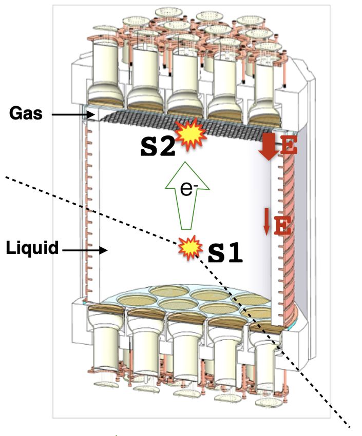
DarkSide-20k: Data Acquisition System
Overview, 1.0
‣ Current design for the electronics and data acquisition system (DAQ) accommodates both the large number of
    PDMs and the long drift-time (expected maximum electron drift time ~ 4 ms) of the LAr TPC, and the readout of the
    veto detector
‣ Current strategy of DAQ is to readout all activity in the TPC & veto compatible with ≥ 1 PE, deferring any high-
    level processing & data-reduction schemes until after the (partial) event-building stage
     ➡ Relying on filtering out data rather than completely eliminating events from continuous data stream
‣   Trigger rate during dark matter search data-taking from three major contributions:
       A. Background events from detector material intrinsic radioactivity
       B. Background events from 39Ar (~ 35 Hz from 50 t active UAr)
       C. DCR (< 250 Hz/PDM)
‣   DAQ design has to:
     ➡ Be able to correlate activity in the TPC with activity in the veto detector
     ➡ Have a detection threshold < 1 photon at channel level
     ➡ Handle large background rate in veto detector

     Ashlea Kemp                                      Queen’s University                              11th February 2021
                                                              5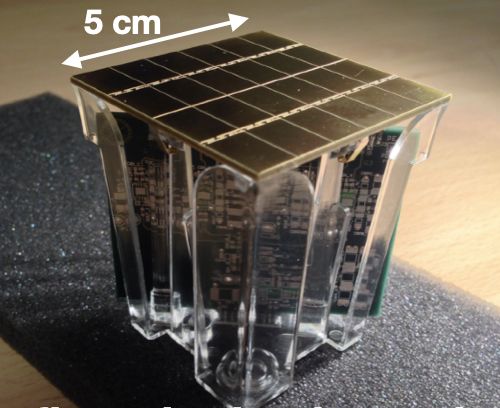
DarkSide-20k: Data Acquisition System
Overview, 1.1
                                        Courtesy of P. Amaudruz, M. Stringer

  Ashlea Kemp      Queen’s University                  11th February 2021
                           6
DarkSide-20k: Data Acquisition System
Challenges

‣ Current detector design envisions ~ 8280 channels for the TPC & 3000 channels for
 the veto digitised by 64-channel, 16-bit CAEN digitisers with fast sampling rate of
 125 MS/s
‣ Given expected rates from background and noise, this results in an unfeasible data
 throughput through the DAQ chain if the full waveforms were to be saved
‣ Various data reduction schemes need to be implemented at the digitiser and FEP
 level to reduce data throughput across the system, and at the TSP level to save on
 disk space

  Ashlea Kemp                         Queen’s University                 11th February 2021
                                              7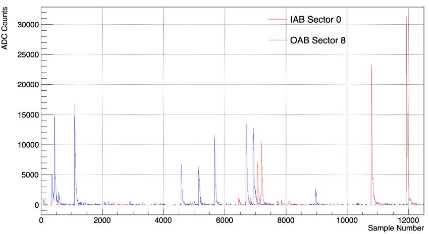
DarkSide-20k: Data Acquisition System
Veto System: Overview                                                            Work-in-progress
‣ Veto encompasses the TPC vessel and is comprised of three main components:
                                                                                                                       OAB1
Inner atmospheric argon (AAr) buffer (IAB) → Gadolinium-loaded plastic → Outer AAr buffer (OAB)
                                                                                                                        IAB1
‣ IAB consists of 45 tonnes LAr, OAB consists of 75 tonnes LAr                                            IAB2
‣ Veto will be used to reject background events from the data collected from the TPC as candidate
    WIMPs, primarily using neutron-capture signals on the Gd-loaded sheets (~ 50%), on LAr (~24%)
                                                                                                       IAB3
    and on H (~15%)
‣   Veto consists of segmented (octagonal) design; separation of segments using acrylic sheets
      ➡ IAB and OAB divided into 8 “sectors” of roughly equal size                                               TPC
      ➡ Segmented design reduces rate of 39Ar pile-up, ~ 1 Bq/kg for AAr
      ➡ Can also use correlation of signals in neighbouring sectors to discriminate between
        candidate neutron-capture events and uncorrelated, random 39Ar/γ events
‣   Challenges of the veto from the DAQ perspective:
        A. High background rate: 5.6 kHz/9.4 kHz per IAB/OAB sector from 39Ar, 30 Hz/23 Hz per
           IAB/OAB sector from γ’s from detector material radioactivity, < 250 Hz from PDM dark
           noise
        B. High data throughput (3000 channels envisioned, 2000 for IAB & 1000 for OAB)
        C. It is vital to not miss neutron-capture signals! Require a maximum veto inefficiency of 10%
‣   Various data reduction schemes need to be implemented at different layers of DAQ chain such
    that DAQ is not overwhelmed with veto data whilst ensuring all important data is stored

      Ashlea Kemp                                                   Queen’s University                                 11th February 2021
                                                                            8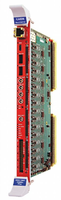
DarkSide-20k: Data Acquisition System
Veto System: Channel & Digitiser Level
Current Readout Proposal: Work-in-progress
  ‣ Sample at 12.5 MS/s (factor of 10 in data reduction compared to TPC)
  ‣ Timing resolution is not as important for veto

  ADC

   Ashlea Kemp                            Queen’s University
                                                                                        t
                                                                           11th February 2021
                                                  9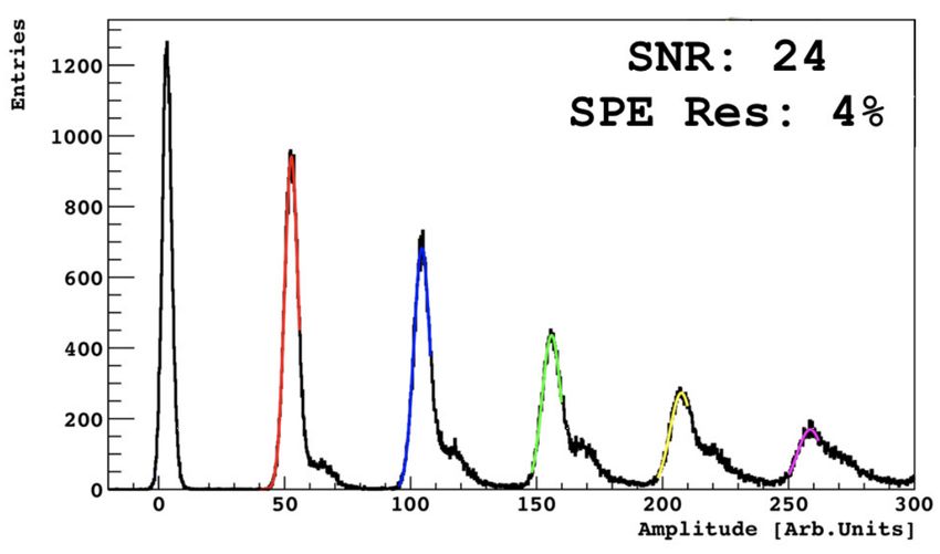
DarkSide-20k: Data Acquisition System
Veto System: Channel & Digitiser Level
Current Readout Proposal: Work-in-progress
  ‣ Sample at 12.5 MS/s (factor of 10 in data reduction compared to TPC)
  ‣ Timing resolution is not as important for veto
On channel-basis, use pulse-finding algorithm in FPGA to identify SiPM signals
  ‣ Dynamic Acquisition Window (DAW): only recording segments of digitised waveform around
   a pulse; removes recording only baseline
  ‣ In example waveform below, only waveform segments in grey boxes are recorded

  ADC

   Ashlea Kemp                            Queen’s University
                                                                                           t
                                                                              11th February 2021
                                                  10
DarkSide-20k: Data Acquisition System
Veto System: FEP Level
Work-in-progress
FEP Each FEP reads input from 6, 64-channel digitisers: 8 FEPs in total
× 64 → ×6→ yields 3000 channels in total
Max output rate per digitiser = 125 MB/s (uncompressed raw data
equivalent)
‣ At FEP, can perform pulse analysis on individual channel waveforms
➡ Single PE hits, i.e. from dark noise, can be compressed into charge and time
information only (QT), ~ 10 B in size
➡ Keep waveform segments for > 1 PE pulses/ pile-up events for approx 10 us, ~
256 B of data/segment
➡ Early simulations of 39Ar, γ’s and neutron captures in the veto indicate a 25% -
35% reduction in data throughput from compressing single PE hits into QT only
‣ At FEP, will also sum together waveforms over multiple channels before sending data
to TSP to ensure output rate does not surpass 125 MB/s FEP output limit
➡ Early simulations of 39Ar, γ’s and neutron captures in the veto indicate performing
QT on single PE pulses and summing together groups of channels into single
waveforms should fit into available bandwidth for FEP output
➡ Number of channels summed together at this stage yet to be optimised; trade off
between retaining good SNR without losing physics information
Simulated waveform of a single channel inside the inner AAr buffer (veto)
Ashlea Kemp Queen’s University 11th February 2021
11DarkSide-20k: Data Acquisition System
Veto System: TSP Level Work-in-progress
‣ At TSP level, open a TPC-veto coincidence window (~ 1 ms in length) about
the time an event is observed in TPC - only look at veto data within this window Two example summed
➡ Relies on correlating TPC-veto information in real time sector WFs (one IAB,
one OAB) constructed
➡ Strategy refers to a “typical” high-mass analysis with perfect online by adding together ZLE
reconstruction; other analysis use cases exist for which major adjustments segments from individual
may be necessary to allow some reprocessing & handle special cases channels of 1 ms TPC-
veto coincidence window
‣ Need to develop an algorithm to decide what parts of waveform to save to containing 1 neutron
disk capture, 39Ar and
background γ ’s
‣ One potential idea:
normalised to their
➡ Sum together waveforms for each sector expected rates
➡ Only save WF segments of pulses which correspond to an energy
deposition > 600 keV
➡ 39Ar endpoint = 565 ± 5 keV
➡ 600 keV threshold would remove majority of 39Ar background; energy
deposition of neutron-captures γ >> 600 keV
‣ Threshold needs to be optimised to ensure neutron-capture detection Mean veto event rate (assuming a
145 Hz TPC rate) as a function of threshold
efficiency > 95%, whilst minimising amount of background data written to disk applied estimated using simulations of 1 ms
‣ Veto event size estimates based on saving waveform segments from each TPC-veto coincidence window containing
sector that cross threshold in TPC-veto coincidence window 1 neutron-capture, 39Ar and background γ ’s
normalised to their expected rates
➡ Could consider saving waveform segments from finer grouping of
channels instead of sector sums for further reconstruction information
down the chain,
➡ One example: save waveform segments from groups of channels
clustered together for position reconstruction purposes
Ashlea Kemp Queen’s University 11th February 2021
12DarkSide-20k: Conclusions and Outlook
Thank you - Questions?
‣ The DarkSide-20k experiment intends to stream data continuously during operation via a software-
based trigger system
‣ Large number of channels and fast sampling rate of digitisers poses various logistical challenges to
the data acquisition (DAQ) system if no data reduction is employed at the different layers of the DAQ
chain
‣ The veto detector has different data requirements to the TPC; has to be able to record high energy
neutron-capture γ events
To deal with high expected background rates from 39Ar, γ’s from detector material, veto DAQ chain
‣
will employ a combination of data reduction schemes, such as dynamic acquisition windows (DAW),
charge-time (QT) compression, waveform summation and threshold-based self-trigger decisions
‣ Other potential veto readout strategies are being explored, for example, saving veto data stream
independently of TPC activity, and saving all veto information as QT summary information
Ashlea Kemp Queen’s University 11th February 2021
13DarkSide-20k: Backup
S1 Signal Prompt Light
Fprompt =
Total Light
‣ Property of LAr scintillation: electronic recoils ERs (β, γ)
generate much more late light in comparison to nuclear
recoils NRs (i.e. WIMP-induced)
‣ Pulse-shape discrimination (PSD) is a technique to
discriminate NRs from ERs based on their time profiles
‣ Introduce discriminator parameter Fprompt: ratio of prompt
light to total light generated in an event
➡ ERs, which generate higher fraction of late light,
typically have lower Fprompt values than NRs
ER background suppression of ~ 108 from PSD in LAr Fprompt vs S1: https://indico.ph.qmul.ac.uk/
indico/getFile.py/access?
resId=0&materialId=slides&confId=428
Ashlea Kemp Queen’s University 11th February 2021
14DarkSide-20k: Backup
S2 Signal
‣ S2/S1 ratio can also be used discriminate between ERs and NRs
➡ ERs produce more free, ionised electrons compared to NRs, thus
have a larger S2 signal compared to NRs; can be used to
distinguish between interactions with equal S1 signals
‣ TPC technology allows for powerful position reconstruction
➡ Free electrons all drift at the same velocity; the time difference
between S1 and S2 can be used to determine z-position
➡ Drift speed of electron in 200 V/cm applied field is ~1 mm/μs
➡ Pattern of the S2 signal on the top PMT array used for xy
reconstruction
➡ Full 3D position reconstruction can discriminate surface
backgrounds from the edge of the detector
TPC cross-section: https://indico.ph.qmul.ac.uk/indico/
getFile.py/access?resId=0&materialId=slides&confId=428
Ashlea Kemp Queen’s University 11th February 2021
15DarkSide-20k: Backup
Detailed DAQ Chain Overview
1. Analog signals fed into VX2740 digitiser modules designed and produced by CAEN. The 64-channel VX2740 digitises the signal with a
sampling rate of 125 MS/s.
2. Data are analysed online in the digitisers in order to identify the pulses from SiPM signals. This is referred to as pulse finding and is
performed within the VX2740 field-programmable gate array (FPGA).
3. Data (typically waveform fragments) are transferred from the digitisers to the front-end processors (FEP) using ethernet Gbit/s links. Each
FEP is a PC collecting data from 8/9 digitisers through a commercial network.
4. Pulses identified by the pulse finder in FPGA are analysed to extract their time and charge information (QT). This is called pulse analysis and
can performed either in the digitiser or the FEPs.
5. FEPs arrange the information into time-slices that contain all the data within a time window of ~ 1s.
6. FEPs send the time slices to a network switch to distribute data; all the data corresponding to a particular time slice are sent to the same
Time Slice Processor (TSP).
7. TSPs reconstruct event-level information from the time slices, associating the S1 and S2 signals and identifying the event types.
8. TSPs send data to be written to disk.
Ashlea Kemp Queen’s University 11th February 2021
16You can also read