Toothed belt axis units ELGE - Festo
←
→
Page content transcription
If your browser does not render page correctly, please read the page content below
Toothed belt axis units ELGE

 This product is also available as a modular mechanical system
 Toothed belt axis ELGR-TB
Toothed belt axis units ELGE NEW

Key features
At a glance
Plug and work with the Simplified Motion Series

The simplicity of pneumatics is now combined for the first time with the There is no need for any software since operation is simply based on the "plug
advantages of electric automation thanks to the Simplified Motion Series. and work" principle. Digital I/O (DIO) and IO-Link are always automatically
These integrated drives are the perfect solution for all users who are looking for included – a product with two types of control as standard.
an electric alternative for very simple movement and positioning tasks between
two mechanical end positions, but don't want the commissioning process for
traditional electric drive systems that can often be quite complex.

Integrated Single Standardised Connected
The integrated electronics in the drive For commissioning, simply set all rele- Electrical connection via Use of extended functions possible via
are at the core of the Simplified Motion vant parameters directly on the drive: M12 plug design IO-Link:
Series. • Speed and force • Power (4-pin): power supply for the • Motion parameters can be set
 • Reference end position and motor remotely
 cushioning • Logic (8-pin): control signal, sensor • Copy and backup function for
 • Manual operation signal and power for the integrated transferring parameters
 electronics • Read function for extended process
 parameters

The functions of the Simplified Motion Series
Basic profile for movement between two end positions: Extended motion profile for simplified press-fitting and clamping functions:
with speed control with speed and force control
v v

 A B A C B
 l l

• These drives are designed for simple movements between two end positions.
• Proximity switches are required in order to implement any intermediate positions.

The products in the Simplified Motion Series
Spindle axis unit Mini slide unit Electric cylinder unit
ELGS-BS-KF EGSS-BS-KF EPCS

Toothed belt axis unit Toothed belt axis unit Rotary drive unit
ELGS-TB-KF ELGE ERMS

2 d Internet: www.festo.com/catalogue/... Subject to change – 2021/01
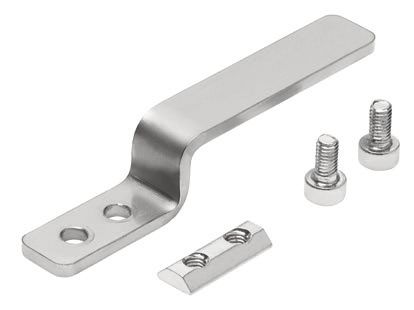
NEW Toothed belt axis units ELGE

Key features
At a glance
 • Without external servo drive: all the necessary electronic components are
 combined in the integrated drive
 • Two control options integrated as standard: digital I/O and IO-Link
 • Complete solution for simple movements between two mechanical end
 positions
 • Protected against external influences by internal guide
 • Simplified commissioning: all parameters can be manually set directly on the
 drive
 • No special expertise required for commissioning
 • End position feedback similar to that of a conventional proximity switch is
 integrated as standard
 • Free choice of flexible motor mounting on four sides
 • Cost-optimised design for tasks that require simpler yet highly cost-efficient
 solutions with a service life of 5,000 km

Modular and flexible with motor, motor mounting kit and servo drive
This product is also available within the Optimised Motion Series as toothed belt axis ELGR-TB:
 Toothed belt axes for tasks that require simpler yet highly cost-efficient solutions in cost-optimised design with a long service
 life. Ideal for pick & place tasks and for transporting small loads of less than 15 kg.
 • 1 driven slide, optionally additional, freely movable slides
 • Extended guide, additional mounting options
 • Free choice of flexible motor mounting on 4 sides
 • Guide variants: recirculating ball bearing guide for moderate loads or plain-bearing guide for low loads
 • Modular: individual combinations with motor, motor mounting kit and servo drive

 Possible combinations with Festo drives
 Electric cylinder EPCO on toothed belt axis unit ELGE

 2 2

 1 1

 Size Accessories
 [1] EPCO [2] ELGE Slot nut Centring sleeve Screw Washer
 16 35 NST-3-M3 (x4) ZBH-7 (x2) M3x10 (x4) –

2021/01 – Subject to change d Internet: www.festo.com/catalogue/... 3
Toothed belt axis units ELGE NEW

Peripherals overview
 Top
 1
Rear Right

Left Front 2
 Underneath
 3
 4

 5 6

 7

 8

 9

 10

4 d Internet: www.festo.com/catalogue/... Subject to change – 2021/01
NEW Toothed belt axis units ELGE

Peripherals overview
 Accessories
 Type/order code Description a Page/Internet
 [1] Centring sleeve • For centring loads and attachments on the slide 21
 ZBH • 2 centring sleeves included in the scope of delivery of the axis
 [2] Profile mounting For mounting the axis on the bearing cap 20
 MUE
 [3] Slot nut For mounting attachments 21
 NST
 [4] Switch lug1) For sensing the slide position 20
 EAPM-L4-SLS
 [5] Sensor bracket1) Adapter for mounting the inductive proximity switches on the axis 20
 EAPM-L4-SHS
 [6] Proximity switch, T-slot1) • Inductive proximity switch, for T-slot 21
 SIES-8M • 1 switch lug and 1 sensor bracket are included in the scope of delivery with the order code SA, SB
 [7] Supply cable For connecting load and logic supply 22
 NEBL-T12
 [8] Connecting cable For connection to a controller 22
 NEBC-M12
 [9] Adapter • Connection between the motor and the IO-Link master 22
 NEFC-M12G8 • Only for use with IO-Link Port Class A Master (recommended)
 [10] IO-Link master USB For straightforward use of the mini slide unit via IO-Link 22
 CDSU-1

1) Proximity switches are optional and only required in order to sense any intermediate positions.

 Motor attachment variants
 [AT] Top [AD] Underneath [AL] Left [AR] Right

 a
 a

 Control elements

 a 1
 [1] Pushbutton actuators for parameterisation and control

2021/01 – Subject to change d Internet: www.festo.com/catalogue/... 5
Toothed belt axis units ELGE NEW

Type codes
001 Series 010 Bus protocol/activation
ELGE Gantry axis PLK PNP and IO-Link®
 NLK NPN and IO-Link®
002 Drive system
TB Toothed belt 011 End-position sensing
 AA With integrated end-position sensing
003 Guide
 Recirculating ball bearing guide 012 Cable outlet direction
 AT Top
004 Size AD Underneath
35 35 AL Left
 AR Right
005 Stroke
50 50 013 Motor position
100 100 FR Front right
150 150 FL Front left
200 200 RR Rear right
250 250 RL Rear left
300 300
350 350 014 Profile mounting
400 400 ...MA 1 ... 2
450 450
500 500 015 Proximity sensor, inductive, slot 8, N/O contact, cable 7.5 m
550 550 ...SA 0 ... 6
600 600
650 650 016 Proximity sensor, inductive, slot 8, N/C contact, cable 7.5 m
700 700 ...SB 1 ... 6
750 750
800 800 017 Slot nut for mounting slot
 ...NM 1 ... 99
006 Stroke reserve
0H 0 mm 018 Electrical accessories
 None
007 Motor type L1 Adapter for operation as IO-Link® device
ST Stepper motor ST
 019 Operating instructions
008 Controller With operating instructions
M Integrated DN No operating instructions

009 Control panel
H1 Integrated

6 d Internet: www.festo.com/catalogue/... Subject to change – 2021/01
NEW Toothed belt axis units ELGE

Data sheet

 -N- Size
 35

 -T- Stroke length
 50 ... 800 mm

 General technical data
 Size 35
 Design Electromechanical axis with toothed belt and integrated drive
 Motor type Stepper motor
 Guide Recirculating ball bearing guide
 Mounting position Horizontal
 Working stroke [mm] 50 ... 800
 Stroke reserve [mm] 0
 Additional functions Integrated end-position sensing
 User interface
 Display LED
 Homing Positive fixed stop block
 Negative fixed stop block
 Type of mounting With female thread
 With accessories
 With centring pin, centring sleeve
 Max. line length
 Inputs/outputs [m] 15
 IO-Link operation [m] 20

 Mechanical data
 Size 35
 Max. payload [kg] 2.8
 Max. feed force Fx [N] 50
 Speed1) [m/s] 1.2
 Speed press [m/s] 0.024
 Max. acceleration [m/s2] 8.5
 Repetition accuracy [mm] ±0.1
 Position sensing For proximity switch
 Via IO-Link

1) It is not possible to reach the maximum speed of 1.2 m/s with strokes < 250 mm.

2021/01 – Subject to change d Internet: www.festo.com/catalogue/... 7
Toothed belt axis units ELGE NEW

Data sheet
 Toothed belt
 Size 35
 Pitch [mm] 2
 Elongation1) [%] 0.094
 Effective diameter [mm] 18.46
 Feed constant [mm/rev.] 58

1) At max. feed force

 Electrical data
 Size 35
 Motor
 Nominal voltage DC [V] 24 (±15%)
 Nominal current [A] 5.3
 Max. current consumption (load) [A] 5.3
 Max. current consumption (logic) [mA] 300
 Encoder
 Rotor position encoder Absolute encoder, single turn
 Rotor position sensor measuring principle Magnetic
 Rotor position encoder resolution [bit] 16

 Interfaces
 Size 35
 Parameterisation interface
 IO-Link Yes
 User interface Yes
 Digital inputs
 Number 2
 Switching logic PNP
 NPN
 Properties Not galvanically isolated
 Configurable
 Specification Based on IEC 61131-2, type 1
 Working area [V] 24
 Digital outputs
 Number 2
 Switching logic PNP
 NPN
 Rotor position encoder Absolute encoder, single turn
 Properties Not galvanically isolated
 Configurable
 Max. current [mA] 100

8 d Internet: www.festo.com/catalogue/... Subject to change – 2021/01
NEW Toothed belt axis units ELGE

Data sheet
 Technical data – IO-Link
 Size 35
 SIO-mode support Yes
 Communication mode COM3 (230.4 kBaud)
 Connection technology Plug
 Port class A
 Number of ports 1
 Process data width OUT [bytes] 2
 Process data content OUT [bit] 1 (Move in)
 [bit] 1 (Move out)
 [bit] 1 (Quit Error)
 Process data width IN [bytes] 2
 Process data content IN [bit] 1 (State Device)
 [bit] 1 (State Move)
 [bit] 1 (State in)
 [bit] 1 (State out)
 Service data contents IN [bit] 32 (Force)
 [bit] 32 (Position)
 [bit] 32 (Speed)
 Minimum cycle time [ms] 1
 Data memory required [Kilobyte] 0.5
 Protocol version sDevice V 1.1

 Operating and environmental conditions
 Size 35
 Insulation class B
 Ambient temperature [°C] 0 ... +50
 Storage temperature [°C] –20 ... +60
 Note on ambient temperature Above an ambient temperature of 30°C, the power must be reduced by 2% per K
 Temperature monitoring Switch-off for excessive temperature
 Integrated precise CMOS temperature sensor with analogue output
 Relative humidity [%] 0 ... 90
 Protection class III
 Degree of protection IP20
 Duty cycle [%] 100
 CE marking To EU EMC Directive
 To EU RoHS Directive
 KC mark KC-EMV
 Certification RCM mark
 Vibration resistance Transport application check with severity level 1 to FN 942017-4 and EN 61800-2 and EN 61800-5-1
 Shock resistance Shock test with severity level 1 to FN 942017-5 and EN 61800-2
 Maintenance interval Life-time lubrication

2021/01 – Subject to change d Internet: www.festo.com/catalogue/... 9
Toothed belt axis units ELGE NEW

Data sheet
 Weight
 Size 35
 Basic weight with 0 mm stroke [g] 2490
 Additional weight per 10 mm stroke [g] 25
 Additional weight of moving mass [g] 0.31
 per 10 mm stroke

 Materials
Sectional view

 1 2 3 4 5

 Axis
 [1] Bearing cap, profile Anodised wrought aluminium alloy
 [2] Guide rods Hardened and hard-chromium plated tempered steel
 [3] Slide, profile Anodised wrought aluminium alloy
 [4] Toothed belt Polychloroprene with glass cord and nylon coating
 [5] Belt pulley High-alloy stainless steel
 Note on materials RoHS-compliant
 Contains paint-wetting impairment substances

10 d Internet: www.festo.com/catalogue/... Subject to change – 2021/01
NEW Toothed belt axis units ELGE

Data sheet
Pin allocation
Power supply Logic interface
Plug Plug
M12x1, 4-pin, T-coded to EN 61076-2-111 M12x1, 8-pin, A-coded to EN 61076-2-101

 When used with digital I/O
 Pin Function Pin Function
 1 Power supply (24 V DC) 1 Logic power supply (24 V DC)
 2 Reference potential, power supply (GND) 2 Digital output 1 (State "In")
 3 Reserved, do not connect 3 Digital output 2 (State "Out")
 4 Functional earth (FE) 4 Reference potential, logic power supply (GND)
 5 Digital input 1 (Move "In")
 6 Digital input 2 (Move "Out")
 7 Reserved, do not connect
 8 Reference potential, logic power supply (GND)

 When used with IO-Link
 Pin Function
 1 L+ IO-Link power supply (24 V DC)
 2 Reserved, do not connect
 3 C/Q communication with the IO-Link master
 4 L – Reference potential, IO-Link power supply (0 V)
 5 Reserved, do not connect
 6 Reserved, do not connect
 7 Reserved, do not connect
 8 L – Reference potential, IO-Link power supply (0 V)

2021/01 – Subject to change d Internet: www.festo.com/catalogue/... 11
Toothed belt axis units ELGE NEW

Data sheet

Characteristic load values
The indicated forces and torques refer
to the centre of the guide. The point of
application of force is the point where
the centre of the guide and the longi-
tudinal centre of the slide intersect.
These values must not be exceeded
during dynamic operation. Special
attention must be paid to the
deceleration phase.

 Max. permissible forces and torques for the bearing calculation, for a service life of 5000 km
 Size 35
 Fymax. [N] 50
 Fzmax. [N] 50
 Mxmax. [Nm] 2.5
 Mymax. [Nm] 8
 Mzmax. [Nm] 8

 If the axis is subjected to two or more of the indicated forces and torques simulta-
-H- Note neously, the following equation must be satisfied in addition to the indicated
For a guide system to have a service life of 5000 km, the load comparison factor maximum loads:
must have a value of fv š 1, based on the maximum permissible forces and
torques for a service life of 5000 km. Calculating the load comparison factor:
This formula can be used to calculate a guide value.
 � 1 � | 1 | | 1 | � 1 � | 1 |
The engineering software “PositioningDrives” is available =
 2
 +
 2
 +
 2
 +
 2
 +
 2
 ≤1

for more precise calculations a www.festo.com
 F1/M1 = dynamic value
 F2/M2 = maximum value

12 d Internet: www.festo.com/catalogue/... Subject to change – 2021/01
NEW Toothed belt axis units ELGE

Data sheet
Calculating the service life
The service life of the guide depends on the load. To be able to make a statement These values are only theoretical. You must consult your local Festo contact for a
as to the service life of the guide, the graph below plots the load comparison load comparison factor fv greater than 1.
factor fv against the service life.

Load comparison factor fv as a function of service life l
Example:
A user wants to move an x kg load. Using the formula (a page 5) gives a
value of 1.5 for the load comparison factor fv. According to the graph, the guide
would have a service life of approx. 1500 km. Reducing the acceleration reduces
the My and Mz values. A load comparison factor fv of 1 now gives a service life of
5000 km.

Service life of the motor
The service life of the motor at nominal power is 20000 h.

2021/01 – Subject to change d Internet: www.festo.com/catalogue/... 13
Toothed belt axis units ELGE NEW

Data sheet
 Sizing example
Application data:
• Payload: 2 kg
• Mounting position: Horizontal
• Stroke: 600 mm
• Max. permitted positioning time: 1 s (one direction)

Step 1: Selection of the size from the table a page 7

Mechanical data
Size 35
Max. payload [kg] 2.8

Step 2: Selection of max. speed level v for payload m Step 3: Reading off the min. positioning time t for stroke l

 Horizontal l = 50 mm
 l = 100 mm
 l = 200 mm
 l = 300 mm
 l = 400 mm
 l = 500 mm
 l = 600 mm
 l = 700 mm
 l = 800 mm
aMax. speed level for payload: level 9 aMin. positioning time for 600 mm at level 9: 0.75 s

Result
The application can be implemented using ELGE-TB-35-600. A minimum positioning time (one direction) of 0.75 s is achieved. Longer positioning times can be selected
at any time using a lower speed level.

14 d Internet: www.festo.com/catalogue/... Subject to change – 2021/01
NEW Toothed belt axis units ELGE

Data sheet
Mass m as a function of speed level v
Size 35

 Horizontal

 Note:
 The lines represent the maximum values. The lower speed levels can be set at any
 time.

Positioning time t as a function of speed level v and stroke l
Size 35

 l = 50 mm
 l = 100 mm
 l = 200 mm
 l = 300 mm
 l = 400 mm
 l = 500 mm
 l = 600 mm
 l = 700 mm
 l = 800 mm

Feed force F as a function of force level F1

 ELGE-TB-35

2nd moment of area

 Y-axis Size 35
 Iy [mm4] 4.19x10³
 Iz [mm4] 3.77x10³
 Z-axis

Recommended deflection limits
Adherence to a maximum deflection of 0.5 mm is recommended so as not to
impair the functional performance of the axes. Greater deformation can result in
increased friction, greater wear and reduced service life.

2021/01 – Subject to change d Internet: www.festo.com/catalogue/... 15
Toothed belt axis units ELGE NEW

Data sheet
Dimensions – With motor Download CAD data a www.festo.com
ELGE-...-AT/AD

ELGE-...-AR/AL

 [1] Motor
 [2] Connection to logic interface
 [3] Connection to power supply
 + = plus stroke length

Size B1 H1 H2 L1 L2 L3

ELGE-...-AT-FL 108.3 134.5 73.5 180.7 95.6 84.3
ELGE-...-AD-FR 108.3 134.5 73.5 180.7 95.6 84.3
ELGE-...-AR-RR 80 136.5 73.5 219.8 95.6 84.3
ELGE-...-AL-RL 80 136.5 73.5 219.8 95.6 84.3

16 d Internet: www.festo.com/catalogue/... Subject to change – 2021/01
NEW Toothed belt axis units ELGE

Data sheet
Dimensions Download CAD data a www.festo.com

 + plus stroke length

Profile
ELGR-35

 Size B1 B2 B3 B4 B5 B6 B7 D1 D2 D3 D4 H1 H2 H3 H4 H5 H6
 @ @ @ @
 H7 H7 H7
 35 37 35 20 7.5 9.5 1 17.5 8 15 27 7 80 39 78 19 40 7.5

 Size H7 H8 H9 H10 H11 H12 H13 H14 H15 L3 L4 L5 L6 L9 T1 T2 T3
 +0.1
 35 63 39 21 9.5 15.5 13.5 49 23.5 20 51 25.5 3 45 30 3.1 1.6 1.6

 Size L1 L2 L7 L8 L10 n

 35 178 89 76 70 20 1

2021/01 – Subject to change d Internet: www.festo.com/catalogue/... 17
Toothed belt axis units ELGE NEW

Ordering data
Ordering data
 Size Stroke Part no. Type
 35 100 8083931 ELGE-TB-35-100-0H-ST-M-H1-PLK-AA-AT-FR
 200 8083932 ELGE-TB-35-200-0H-ST-M-H1-PLK-AA-AT-FR
 300 8083933 ELGE-TB-35-300-0H-ST-M-H1-PLK-AA-AT-FR
 400 8083934 ELGE-TB-35-400-0H-ST-M-H1-PLK-AA-AT-FR
 500 8083935 ELGE-TB-35-500-0H-ST-M-H1-PLK-AA-AT-FR
 600 8083936 ELGE-TB-35-600-0H-ST-M-H1-PLK-AA-AT-FR

18 d Internet: www.festo.com/catalogue/... Subject to change – 2021/01
NEW Toothed belt axis units ELGE

Ordering data
 Ordering table
 Size 35 Conditions Code Enter
 code
 Module no. 8083929
 Series ELGE ELGE ELGE
 Drive system Toothed belt -TB -TB
 Guide Recirculating ball bearing guide
 Size 35 -...
 Stroke [mm] 50, 100, 150, 200, 250, 300, 350, 400, 450, 500, 550, 600, 650, 700, 750, 800 -...
 Stroke reserve [mm] 0 -0H -0H
 Motor type Stepper motor ST -ST -ST
 Controller Integrated -M -M
 Control panel Integrated -H1 -H1
 Bus protocol/control NPN and IO-Link -NLK
 PNP and IO-Link -PLK
 End-position sensing With integrated end-position sensing -AA -AA
 Cable outlet direction Top -AT
 Underneath -AD
 Left -AL
 Right -AR
 Motor position Front left -FL
 Front right -FR
 Rear left -RL
 Rear right -RR
 Profile mounting None
 1 ... 2 +...MA
 Proximity switch (SIES), inductive, slot None
 type 8, N/O contact, cable 7.5 m, in-
 cluding switch lug and sensor bracket 1 ... 6 ...SA
 Proximity switch (SIES), inductive, slot None
 type 8, N/C contact, cable 7.5 m, in-
 cluding switch lug and sensor bracket 1 ... 6 ...SB
 Slot nut for mounting slot None
 1 ... 99 ...NM
 Electrical accessories None
 Adapter for operation as IO-Link device +L1
 Operating instructions With operating instructions
 Without operating instructions DN

2021/01 – Subject to change d Internet: www.festo.com/catalogue/... 19
Toothed belt axis units ELGE NEW

Accessories
Profile mounting MUE Material:
(order code MA) Anodised aluminium
 RoHS-compliant

Dimensions and ordering data
For size B1 B2 B3 B5 D1 D2 H1 H2 H3 H4
 @ @
 H7
35 51 8 43 4 3.4 5 78 6 5.5 2.3

For size H5 L1 L2 L3 L4 Weight Part no. Type
 [g]
35 11 40 20 94 86 20 558042 MUE-50

Sensor bracket EAPM-…-SHS Material:
Switch lug EAPM-…-SLS Switch lug: Galvanised steel
(order code SA/SB) Sensor bracket: Anodised wrought
 aluminium alloy
 RoHS-compliant

 EAPM-L4-SHS

 EAPM-L4-SHS

Dimensions and ordering data
For size B1 H1 L1 Weight Part no. Type
 [g]
Sensor bracket
35 9 6.5 44 20 567537 EAPM-L4-SHS

Switch lug
35 10 11 57.5 15 567538 EAPM-L4-SLS

20 d Internet: www.festo.com/catalogue/... Subject to change – 2021/01
NEW Toothed belt axis units ELGE

Accessories
 Ordering data
 For size Comment Order code Part no. Type PE1)

 Slot nut NST
 35 For mounting slot NM 558045 NST-3-M3 1

 Centring sleeve ZBH2)
 35 For slide – 186717 ZBH-7 10

1) Packaging unit
2) 2 centring sleeves included in the scope of delivery of the axis

 Ordering data – Proximity switches for T-slot, inductive Data sheets a Internet: sies
 Type of mounting Electrical connection Switching Cable length Order code Part no. Type
 output [m]
 N/O contact
 Insertable in the Cable, 3-wire PNP 7.5 SA 551386 SIES-8M-PS-24V-K-7,5-OE
 slot from above, Plug M8x1, 3-pin 0.3 – 551387 SIES-8M-PS-24V-K-0,3-M8D
 flush with the Cable, 3-wire NPN 7.5 – 551396 SIES-8M-NS-24V-K-7,5-OE
 cylinder profile Plug M8x1, 3-pin 0.3 – 551397 SIES-8M-NS-24V-K-0,3-M8D

 N/C contact
 Insertable in the Cable, 3-wire PNP 7.5 SB 551391 SIES-8M-PO-24V-K-7,5-OE
 slot from above, Plug M8x1, 3-pin 0.3 – 551392 SIES-8M-PO-24V-K-0,3-M8D
 flush with the Cable, 3-wire NPN 7.5 – 551401 SIES-8M-NO-24V-K-7,5-OE
 cylinder profile Plug M8x1, 3-pin 0.3 – 551402 SIES-8M-NO-24V-K-0,3-M8D

 Ordering data – Connecting cables Data sheets a Internet: nebu
 Electrical connection, left Electrical connection, right Cable length Part no. Type
 [m]
 Straight socket, M8x1, 3-pin Cable, open end, 3-wire 2.5 541333 NEBU-M8G3-K-2.5-LE3
 5.0 541334 NEBU-M8G3-K-5-LE3
 Angled socket, M8x1, 3-pin Cable, open end, 3-wire 2.5 541338 NEBU-M8W3-K-2.5-LE3
 5.0 541341 NEBU-M8W3-K-5-LE3

 -H- Note
 Proximity switches are optional and
 only required in order to sense any
 intermediate positions.

2021/01 – Subject to change d Internet: www.festo.com/catalogue/... 21
Toothed belt axis units ELGE NEW

Accessories
Ordering data – Supply cables Data sheets a Internet: nebl
 Electrical connection, left Electrical connection, right Cable length Part no. Type
 [m]
 Angled socket, M12x1, 4-pin Cable, open end, 4-wire 2 8080778 NEBL-T12W4-E-2-N-LE4
 5 8080779 NEBL-T12W4-E-5-N-LE4
 10 8080780 NEBL-T12W4-E-10-N-LE4
 15 8080781 NEBL-T12W4-E-15-N-LE4
 Straight socket, M12x1, 4-pin Cable, open end, 4-wire 2 8080790 NEBL-T12G4-E-2-N-LE4
 5 8080791 NEBL-T12G4-E-5-N-LE4
 10 8080792 NEBL-T12G4-E-10-N-LE4
 15 8080793 NEBL-T12G4-E-15-N-LE4

Ordering data – Connecting cables Data sheets a Internet: nebc
 Electrical connection, left Electrical connection, right Cable length Part no. Type
 [m]
 Angled socket, M12x1, 8-pin Cable, open end, 8-wire 2 8094476 NEBC-M12W8-E-2-N-B-LE8
 5 8094478 NEBC-M12W8-E-5-N-B-LE8
 10 8094481 NEBC-M12W8-E-10-N-B-LE8
 15 8094479 NEBC-M12W8-E-15-N-B-LE8
 Straight plug, M12x1, 8-pin 2 8080786 NEBC-M12W8-E-2-N-M12G8
 5 8080787 NEBC-M12W8-E-5-N-M12G8
 10 8080788 NEBC-M12W8-E-10-N-M12G8
 15 8080789 NEBC-M12W8-E-15-N-M12G8
 Straight socket, M12x1, 8-pin Cable, open end, 8-wire 2 8094480 NEBC-M12G8-E-2-N-B-LE8
 5 8094477 NEBC-M12G8-E-5-N-B-LE8
 10 8094482 NEBC-M12G8-E-10-N-B-LE8
 15 8094475 NEBC-M12G8-E-15-N-B-LE8
 Straight plug, M12x1, 8-pin 2 8080782 NEBC-M12G8-E-2-N-M12G8
 5 8080783 NEBC-M12G8-E-5-N-M12G8
 10 8080784 NEBC-M12G8-E-10-N-M12G8
 15 8080785 NEBC-M12G8-E-15-N-M12G8

-H- Note
The cables are positioned at a 45°
angle to the axis.

Ordering data – IO-Link master USB Data sheets a Internet: cdsu
 Description Cable length Part no. Type
 [m]
 • For using the unit with IO-Link 0.3 8091509 CDSU-1
 • An external power supply plug is additionally required
 (not in scope of delivery)

Ordering data – Adapter Data sheets a Internet: nefc
 Electrical connection, left Electrical connection, right Cable length Part no. Type
 [m]
 Straight socket, M12x1, 8-pin • Straight plug, M12x1, 5-pin 0.3 8080777 NEFC-M12G8-0.3-M12G5-LK
 • Only for use with IO-Link Port Class A
 Master (recommended)

22 d Internet: www.festo.com/catalogue/... Subject to change – 2021/01
You can also read