The University Münster model surgery system for orthognathic surgery - The digital update
←
→
Page content transcription
If your browser does not render page correctly, please read the page content below
Stamm et al. Head & Face Medicine     (2021) 17:31
https://doi.org/10.1186/s13005-021-00278-y

    METHODOLOGY                                                                                                                                Open Access

The University Münster model surgery
system for orthognathic surgery - The digital
update
Thomas Stamm1*              , Dennis Böttcher2 and Johannes Kleinheinz3

    Abstract
    Aim: The aim of this work is to present a digital methodology of a conventional articulator based planning protocol.
    Methods: The digital counterpart consists of intra-oral scans (3Shape) and a free available 3D mesh software
    (Meshmixer, Autodesk). The maxillary position in relation to the reference plane used and the arbitrary hinge axis were
    determined mathematically from landmarks on cephalometric x-rays and frontal photographs. Distances and angles
    were calculated to virtually mount the digital jaws in Meshmixer’s wold frame. Virtual planning is done by cloning and
    moving the jaws according to the preliminary surgery plan. The spatial movements of the jaws are measured by
    attached reference points.
    Results: This digital approach eliminate the need for articulator hardware and laboratory plaster work. It enables all
    planning scenarios as they are also possible with conventional plaster-based procedures. The method is time-saving,
    practical and cost-effective. Standard dimensions of articulators and face-bows have been incorporated in the
    implementation. This reduction of individual patient values puts the accuracy of the presented method within the
    range of conventional model surgery.
    Conclusion: Arbitrary planning will continue to have its place in orthognathic surgery, especially when digital
    methods can improve the overall process. The method presented can be seen as a cost-effective alternative for
    patients who do not require technically complex planning.
    Keywords: Orthognathic surgery, Virtual planning, Orthodontics

Background                                                                           able postoperative situation and the surgeon wants to per-
The essential factors of a successfully treated orthog-                              form a cause-oriented osteotomy to move and stabilize the
nathic surgery case are a) “ortho”-gnathic jaw position,                             jaws or segments in the planned final position.
b) facial improvement, c) good occlusion, and d) bal-                                  Although articulators were never designed for orthog-
anced function. Interdisciplinary collaboration between                              nathic surgery [1] they have been used for decades. Artic-
surgeons and orthodontists strives to meet these factors.                            ulators have fixed, mean-value dimensions with respect to
Without a doubt, each physician involved aims to achieve                             the intercondylar distance. The face-bow places the occlu-
an optimum in his field. This also applies to surgery                                sion in relation to the axis of the articulator, which does
planning, where the orthodontist wants to achieve a treat-                           not correspond to the individual hinge axis of the patient.
                                                                                     This is called arbitrary mounting. In the following, plan-
                                                                                     ning based on fixed average articulator dimensions is
*Correspondence: stammt@uni-muenster.de
1
 Senior Lecturer, Department Orthodontics, University of Münster,                    referred to as ‘arbitrary planning’.
Albert-Schweitzer-Campus 1, Gebäude W 30, D-48149 Münster, Germany
Full list of author information is available at the end of the article

                                       © The Author(s). 2021 Open Access This article is licensed under a Creative Commons Attribution 4.0 International License,
                                       which permits use, sharing, adaptation, distribution and reproduction in any medium or format, as long as you give appropriate
                                       credit to the original author(s) and the source, provide a link to the Creative Commons licence, and indicate if changes were
                                       made. The images or other third party material in this article are included in the article’s Creative Commons licence, unless
                                       indicated otherwise in a credit line to the material. If material is not included in the article’s Creative Commons licence and your
                                       intended use is not permitted by statutory regulation or exceeds the permitted use, you will need to obtain permission directly
                                       from the copyright holder. To view a copy of this licence, visit http://creativecommons.org/licenses/by/4.0/. The Creative
                                       Commons Public Domain Dedication waiver (http://creativecommons.org/publicdomain/zero/1.0/) applies to the data made
                                       available in this article, unless otherwise stated in a credit line to the data.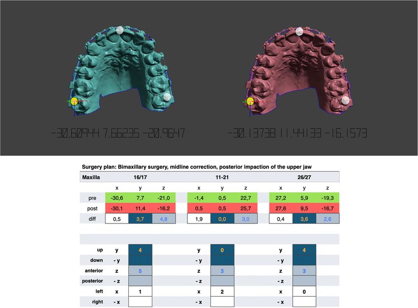
Stamm et al. Head & Face Medicine   (2021) 17:31                                                                            Page 2 of 10

  Surgical planning has developed fundamentally differ-        x-ray, a cephalometric x-ray and special profile and frontal
ent from analogue planning and new waiverless/splintless       photographs. It is important to note that the goal of this
surgery with patient specific implants seem to be emerg-       method is a digital representation of the planning using
ing as the future gold standard. However, high costs and       the SAM 2P including the special hardware necessary for
technical demands of the new technology make these             orthognathic surgery [9]. Therefore, this system is work-
inaccessible to many patients [2]. Moreover, the signifi-      ing arbitrary with the conditions of an anatomic face-bow
cant improvement of the results and benefit for the patient    and standard articulator dimensions.
in comparison with the analog technique is still not              The SAM’s (articulator and face-bow) reference plane
proven. It is therefore necessary to offer a cost-effective    is the axis orbital plane (AOP) which is also the common
method without having to forego the benefits of digital        reference plane for two dimensional cephalometric and
workflows.                                                     conventional articulator-based model surgery in a couple
  Intraoral scanners are of particular importance in           of schemes [10–13]. Although there are some techniques
surgery planning. Due to their high accuracy and prac-         for localization of the AOP in cephalometric radiographs
ticability, they could replace impressions [3], as well as     [14–16] we used a clinical approach. This approach is
scattered dental morphology in cone-beam computed              based on planned cases, where it was necessary to project
tomographs [4]. They are therefore applicable to create        the individual hinge axis and the palpable infraorbital rim
composite virtual skull models and conventional planning       on the cephalometric x-ray to perform a two-dimensional
procedures. Freely available, high-precision software from     planning according to individual measurements. For this
the engineering industry pave the way for experimenting        purpose, the positions were marked with metal markers
with cost-effective planning alternatives.                     on the patient’s skin before a x-ray was taken (Fig. 1).
  Another aspect for the transfer of conventional planning        A retrospective analysis of several marked x-rays from
into a digital workflow is the enormous experience gained      previous cases revealed that the geometric relations
in decades of surgery, which represents a wealth of knowl-     between the maxillary occlusal plane and the face-bow
edge that should not be discarded. Known errors and            plane can be calculated by using four cephalometric land-
inaccuracies are more likely to be accounted for and con-      marks: Pi (Porion inferior, deepest point on the lower
tribute to faster and more practical implementation. The       border of the meatus acusticus externus), Ns (nasal sup-
knowledge and the indication-related application of all        port of the face-bow), Ie (upper incisor edge) and Dc
possible surgical techniques is mandatory for each plan-       (distobuccal cusp of the first permanent upper molar). For
ning system. This fundamental clinical experience cannot       double contours (right/left), the average is taken. Ie and
be replaced by digital algorithms. The aim of this work is     Dc form the maxillary occlusal plane. For simplification
therefore to describe a method of incorporating the coor-      in daily use, a script was written that uses the free soft-
dinate system and rotation axis of a conventional semi-        ware ImageJ [17] to calculate the necessary angles and
adjustable articulator into the digital three-dimensional      distances for transmission to Meshmixer. The theoretical
surgical planning.                                             background is as follows.

Method
The authors’ methodology is based on the principles of
model surgery planning on dental casts described by
Ehmer et al. [5–9]. This system is part of the standard
planning of orthognathic surgery at the University of
Münster that includes the fabrication of intermediate and
final gnathological splints using the semi-adjustable artic-
ulator SAM 2P (SAM Präzisionstechnik GmbH, Gauting,
Germany).
   In the digital version, the impressions are replaced by
intra-oral scans (3Shape A/S, Holmens Kanal 7, 1060
Kopenhagen, Dänemark) and the patient’s individual max-
illary position in relation to the used reference plane as
well as the arbitrary hinge axis are virtually combined
with the 3D mesh software Meshmixer (Autodesk, Inc.             Fig. 1 Clinical approach to the determination of the axis orbital plane.
111 McInnis Parkway San Rafael, CA 94903 USA). With             The individual hinge axis and the right palpable infraorbital rim were
this digital counterpart, face-bow, face-bow bite fork and      indicated with metal markers on the patient’s skin before a
articulator can be omitted. Further diagnostic records for      cephalometric radiograph was obtained. Square and triangular
                                                                markers were used to distinguish between left and right side
digital planning are the clinical examination, a panoramic
Stamm et al. Head & Face Medicine         (2021) 17:31                                                                                      Page 3 of 10

Calculation of the maxillary position in the sagittal plane                     The angle η between Pi − b and a horizontal line is
A schematic representation for calculating the angles                         therefore:
and distances between the face-bow, articulator axis and
occlusal plane is presented in Fig. 2. All calculations are                        η =−α                                                                (6)
performed with script language of ImageJ where standard                         The locate the SAM’s hinge axis on the angled face-bow
tools like Set scale, Brightness/Contrast and Window/Level                    plane its slope must be calculated:
were used.
  After importing and scaling of the cephalometric radio-                          mPi−b = tan η                                                         (7)
graph the above mentioned landmarks are placed with
                                                                                 The angle θ between the occlusal plane and a horizontal
ImageJ’s multi-point tool. The first calculation concerns
                                                                              line can be calculated by the slope of Ie − Dc:
the right-angled triangle between Pi, Ns and b, where b
is the point on the face-bow plane perpendicular to Ns.                                           yIe − yDc
                                                                                   θ = arctan                                                            (8)
The distance Ns-b is constant (30mm) due to the face-                                             xIe − xDc
bow hardware. The distances Pi-Ns, Pi-b and the angle
                                                                                 Thus, the angle λ between face-bow and occlusal plane
α between Pi-Ns and Pi-b are calculated as follows. The
                                                                              is:
calculations shown here refer to the coordinate system of
ImageJ, where the origin is in the upper left corner.                              λ=θ +η                                                                (9)

    Pi − Ns = (xNs − xPi )2 + (yNs − yPi )2           (1)                   Calculation of the arbitrary hinge axis position
                                                                            The ear rods of the SAM face-bow are located in a dis-
               Ns − b                                                       tance of 10 mm behind the articulator’s hinge axis during
    α = arcsin                                                        (2)
               Pi − Ns                                                      mounting of plaster casts. To transfer this position into
                                                                              Meshmixer the following calculations are necessary: i)
    Pi − b = cosα · Pi − Ns                                       (3)     the location of the articulator’s axis (Ax) on the face-
  The angle  between Pi − Ns and a horizontal line could                     bow plane, ii) the distance from Ax perpendicular to the
be calculated by the slope of the Pi-Ns:                                      section (Dc ) on the occlusal plane and iii) the distance
               yNs − yPi                                                      from Dc to the upper incisor edge (Ie).
    mPi−Ns =                                          (4)
              xNs − xPi                                                         The coordinates of Ax 10 mm anterior of Pi on the face-
                                                                              bow plane are: xAx = cos α · 10 and yAx = sin α · 10. With
     = arctan(mPi−Ns )                                               (5)     the coordinates of point Ie (xIe , yIe ) the angle φ between

 Fig. 2 Schematic representation for calculating the angles and distances between the face-bow, articulator axis and occlusal plane. Pi = Porion
 inferior; Ax = hinge axis position of the SAM (10 mm anterior of the ear rods); Ns = Nasal rest of the face-bow; AOP = axis orbital plane represented
 by the face-bow; OE = occlusal plane; Ie = upper incisor edge; Dc = distobuccal cusp of the first permanent upper molar; Dc’ = section of a
 perpendicular line from Ax to the occlusal plane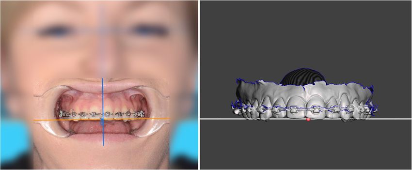
Stamm et al. Head & Face Medicine (2021) 17:31 Page 4 of 10
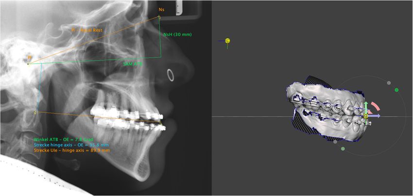
Fig. 3 Left: The following calculations are projected on the cephalometric x-ray: Angle between upper occlusal plane and AOP (7.8◦ ), distance from
the articulator’s hinge axis perpendicular to the upper occlusal plane (35.8mm), and the distance from the latter intersection to the upper incisor
edge (89.9mm). Right: Movement of the hinge axis pivot according to the calculated distances following clock wise rotation of the all objects
around upper incisor edge. Upper and lower jaw are thereby arbitrarily aligned to the AOP in Meshmixer’s world frame
Ax − Ie and a horizontal line could be calculated by: asymmetrically positioned and that both pupils could be
used to assess the facial midline and inclination of the
yIe − yAx occlusal plane. Since no scaling is required for angle mea-
φ = arctan (10)
xIe − xAx surements, a frontal image of the patient, gazing forward
with mouth open and cheek retractors in place is sufficient
The angle ω between Ax − Ie and the occlusal plane is
to assess the occlusal plane (Fig. 4, left).
φ − θ. The distance between the articulator’s axis and the
upper incisor edge could be calculated by
Data transfer to the mesh software
yIe − yAx The intraoral scans are imported into Meshmixer and the
Ax − Ie = (11)
sin φ maxilla is aligned to the world frame’s ground-plane grid.
The world frame is the canonical axis-aligned coordinate
With the disctance Ax − Ie and the angle ω the dis- system, where Y always points upwards, and X always
tance from Ax perpendicular to the occlusal plane could points to the right. In the horizontal plane the maxilla
be calculated by is symmetrically oriented along the palatal suture to the
midsagittal plane and with its occlusal plane parallel to the
Axppd = sin ω · Ax − Ie (12)
grid. Dental midline deviation must be taken into account
(Fig. 4, right), as well as mesial- or distal-positions of the
Therefore, the distance on the occlusal plane from Ie to
posterior teeth in case of asymmetric arches (Fig. 5). Pos-
Axppd is
sible tilts of the occlusal plane around the z-axis (antero-
Axppd posterior) can be adjusted to the exact degree (Fig. 4,
Ie − Axppd = (13) right). The mandible is registered to the maxilla through
tan ω
the bite-scan and is moved passively when the maxilla is
The distances from Eqs. 11 and 12 are the impor- positioned.
tant distances to place the hinge axis in relation to the Once the scans are ideally aligned to the planes mea-
maxillary scan within the Meshmixer software. A graph- suring points should be set. Meshmixer provides pivots
ical representation of the calculations is projected on the for this purpose. Pivots are persistent objects in a scene
cephalometric x-ray (Fig. 3, left). that allow to store or to bound a 3D location to an object.
The number and localisation of the desired measuring
Transverse inclination of the occlusal plane points can be freely selected. Essential for the concept pre-
The assessment of the occlusal plane in transverse direc- sented here, however, is a pivot on the upper incisor edge,
tion is done by means of the interpupillary line. In the ideally in the plane of the skeletal midline. It is not neces-
absence of trauma, tumors, or syndromal conditions, it sary to choose reproducible surfaces, because the pivots
can be assumed that in the majority of skeletal maloc- are placed only once and cloned each time for further
clusions (class II, class III, open bite), the orbits are not processing.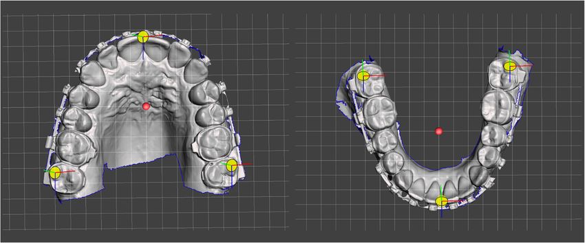
Stamm et al. Head & Face Medicine          (2021) 17:31                                                                                         Page 5 of 10

 Fig. 4 Left: Frontal image of the patient, gazing forward with mouth open and cheek retractors in place. The head must be tilted forward or
 backward so that the aligned teeth are in one plane. A line parallel to the interpupillary line is drawn to assess the maxillary occlusal plane. Right: The
 upper jaw is aligned to Meshmixer’s ground-plane grid according to the reference lines of the frontal image. The dental midline is slightly shifted to
 the right of the mid-sagittal plane (red dot)

  The next step is the alignment in the sagittal plane                          Virtual planning
according to the calculations obtained from the cephalo-                        After generating the preliminary surgical plan, the STL
metric radiograph. For this the pivot on the upper incisor                      jaws including bounded pivots are cloned and used for the
edge is cloned and moved distally along the ground plane                        desired movements. The original STLs remain in their ini-
grid (which coincides with the occlusal plane in this                           tial unoperated positions and are used for calculation of
phase) by the amount of the calculation from Eq. 13. Then                       the distances between pre- and postoperative position. In
it is moved up by the amount of the calculation from                            the following, ’jaw’ always means the corresponding STL
Eq. 12. Now the pivot represents the articulator’s hinge                        file with the measurement pivots bound to it.
axis in relation to the maxilla. Any object bounded to                             In general, bi-maxillary surgical planning starts by
this pivot could be rotated around the pivot’s axis. To                         cloning and moving the upper jaw in its new position.
complete the virtual mounting jaws and pivots must be                           This can be done in a simple way with Meshmixwer’s
angulated to the AOP. To do this, all objects in the scene                      3D transform widget. The widget is located in the center
are bound together and rotated around the x-axis of the                         of transformation of the jaw. Selecting one of the pivots
upper incisor pivot (Fig. 3, right). The size of the rotation                   switches the center of transformation to the center of the
corresponds to the result from Eq. 9. With this rotation,                       pivot which could be helpful for desired rotational move-
the ground-plane grid becomes a parallel to the AOP and                         ments (Fig. 6, upper right). More precise movements can
the scans are in correct relation to this reference plane and                   be made with the transform tool property panel in which
to the arbitrary hinge axis. The scene is ready for virtual                     the numeric-value fields can be directly edited. This is
planning.                                                                       advantageous for fine-tuning the final position.

 Fig. 5 Pivots are used as measurement points on the surface of the jaws, which bind a 3D location to an object
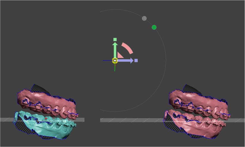
Stamm et al. Head & Face Medicine         (2021) 17:31                                                                                      Page 6 of 10

 Fig. 6 The jaws are color-coded for surgery simulation to visually indicate the pre- and postoperative position. Upper left: Initial situation prior to
 bimaxillary surgery. Upper right: Cloned upper jaw advanced with posterior impaction. The center of transformation is located in the center of the
 pivot (widget) at the upper incisor edge. Lower left: Set back of the cloned lower jaw in final occlusion. Lower right: Top view of merging areas
 between upper and lower occlusal meshes. Early contacts occur in these areas, which must be taken into account during postoperative orthodontic
 treatment

  The lower jaw is moved to its new occlusion in the same                     postoperative lower jaw is bound to the hinge axis pivot
way. Unlike plaster, there is no haptic feedback and the                      and the center of transformation is set to the center of the
meshes can merge into each other. The lack of haptics                         pivot. Depending of the malocclusion an open rotation of
is compensated visually by highlighting the mesh colli-                       approximately two degrees is sufficient.
sions in colour. So the new occlusal contact points are                          If the production of splints outside of Meshmixer is
easy to recognise. After the postoperative positions have                     desired, the corresponding STLs must be exported in
been reached, the movements of the individual jaws can                        their relative positions to each other. In case of lower
be measured. This is done with the point coordinates                          jaw surgery the preoperative maxilla and the postopera-
measuring tool. This measure type allows to query the                         tive open rotated mandible are exported. Similar applies
3D position of a bounded measuring pivot. Three X/Y/Z                         to single upper jaw surgery. In case of two jaw surgery and
coordinates are displayed and are copied into a spread-                       for producing the intermediate splint three STL files are
sheet of the planning protocol. The distances of the pivots                   exported (Fig. 8): i) the postoperative upper jaw, ii) the
between the preoperative and postoperative position are                       unoperated lower jaw, and iii) the postoperative rotated
determined and provide information about the displace-                        lower jaw. The result of the case used here as an example
ment of the jaws according to the X/Y/Z axes (Fig. 7).                        is shown in Fig. 9.
Planning alternatives can be performed by further cloning
of the preoperative jaws and the number of plannings                          Planning protocol
are only limited by the storage of the used computer                          During planning, all necessary information is documented
hardware.                                                                     in a special multi-page planning sheet. This sheet contains
  Once the optimal movements and positions of the jaws                        the cephalometric analysis, the photo analysis, data of
have been determined, the preparation for splint fabri-                       the virtual mounting, model surgery movements (Fig. 7),
cation takes place. Regardless of whether the splints are                     images of pre- and postoperative jaw overlays, an image
designed in Meshmixer or a special dental software, an                        of the new occlusal contacts, a recommendation how to
opening rotation must take place in the thickness of the                      wear elastics postsurgery, and a 3D representation of the
final splint between the upper and lower jaw. For this, the                   new jaw positions in its final occlusion. This sheet is used
Stamm et al. Head & Face Medicine (2021) 17:31 Page 7 of 10
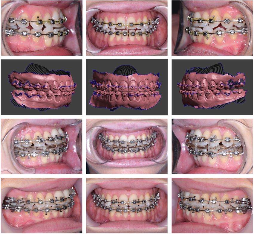
Fig. 7 Initial and cloned upper jaw. Measuring point on tooth 17 is selected and the point coordinates measuring tool displays the X/Y/Z
coordinates. The differences are calculated by entering the values in a spreadsheet of the planning sheet. In this case the maxilla is asymmetrically
advanced by 5 mm on the right side and 3 mm on the left side with a dental midline correction of 2 mm to the left. Simultaneously the jaw is
posterior impacted by 4 mm
by the planning team, the surgeon in the operating theatre However, the authors’ method is an arbitrary pro-
and the orthodontist who will carry out the postoperative cedure and includes the inaccuracies of conventional
treatment. orthognathic surgery planning. Arbitrary means, among
other things, that the used hinge axis is located 10 mm
Results and discussion anterior of the ear rods within a 4-5 mm radius of the
The digital planning procedure presented enables all plan- true hinge axis [1, 18]. Within this radius the arbritrary
hinge axis mounting results in a 10% rate of occlusal errors
ning scenarios as they are also possible with conven-
≥0.34 mm [18] which is more than acceptable for postop-
tional plaster-based procedures. A significant advantage
erative orthodontic treatment. Even the purely rotational
is that articulator hardware and manual plaster work are
and therefore non-physiological movement of approx. two
no longer required. The full potential can unfold when degrees for final splint production does not produce any
intraoral scanners and digital splint fabrication are used. errors that cannot be compensated with postoperative
One of the strength of the presented method is the elim- orthodontics.
ination of many error prone laboratory steps. Removing A further flaw is that the angle between the upper
the impression of dental arches attached with brackets and occlusal plane and the AOP is smaller in cephalometric
wires can lead to dimensional errors and continues with radiographs than in face-bow mounted casts [19], which
plaster model fabrication and handling during physical tends to result in larger upper jaw impactions and more
model surgery. Using intraoral scans and direct printing posterior positions of both jaws [1]. Although we worked
or milling is the most accurate surgical splint production with metal markers to construct the AOP on the cephalo-
today. metric radiograph, this error cannot be excluded. Clinical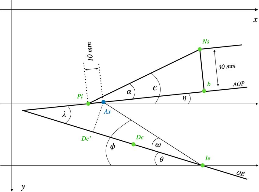
Stamm et al. Head & Face Medicine         (2021) 17:31                                                                                       Page 8 of 10

 Fig. 8 Preparation for splint production for bimaxillary surgery. Intermediate splint: Preoperative lower jaw position with postoperative upper jaw
 position. Final splint: Postoperative upper jaw position with open rotated postoperative lower jaw position. The amount of open rotation could be
 adjusted manually by the 3D widget or by the transform tool property panel

 Fig. 9 Pre- and postoperative images of a skeletal class III patient. As shown in in Figs. 3–7 the surgery plan was a two-jaw procedure with a maxillary
 asymmetric advancement and posterior impaction. The lower jaw was a symmetrically set up and back. Upper row: Preoperative occlusion. Second
 row: Planned occlusion in Meshmixer. Third row: Four weeks postoperative with removable splint and class III elastics. Lower row: Occlusal situation
 at the appointment for plate removal six month after surgery
Stamm et al. Head & Face Medicine            (2021) 17:31                                                                                           Page 9 of 10

studies quantifying this error are lacking so far. Moreover,                      Funding
focusing planning on the occlusal plane solely runs the                           Open Access funding enabled and organized by Projekt DEAL.
risk of not recognizing bony interferences that may result                        Availability of data and materials
from the displacement of the jaws or jaw segments in both                         Not applicable.
the maxilla and mandible.                                                         Declarations
  The use of a wooden tongue depressor is a standard pro-
cedure when assessing occlusal canting [20]. In the clinical                      Ethical approval and consent to participate
application the depressor’s position is influenced by sin-                        Not applicable.
gle tooth position and thereby may indicate an incorrect                          Consent for publication
position of the occlusal plane. In addition, when holding                         Not applicable.
the depressor with the teeth, only the anterior part of the
                                                                                  Competing interests
dental arch is represented which makes the application in                         The authors declare that they have no competing interests.
general insufficient. We therefore use cheek retractors to
assess the whole upper dental arch on photographs. It is                          Author details
                                                                                  1 Senior Lecturer, Department Orthodontics, University of Münster,
a time feasible and dentition-independent procedure that                          Albert-Schweitzer-Campus 1, Gebäude W 30, D-48149 Münster, Germany.
can be easily used during photographic examination. Not                           2 Orthodontist, Department Orthodontics, University of Münster,

only the dental arch, but also the wire plane, the den-                           Albert-Schweitzer-Campus 1, Gebäude W 30, D-48149 Münster, Germany.
                                                                                  3 Head of Department, Department of Cranio-Maxillofacial Surgery, University
tal midline and second order crown angulations can be                             Hospital Münster, Albert-Schweitzer-Campus 1, Gebäude W 30, D-48149
assessed in relation to the interpupillary and midsagittal                        Münster, Germany.
plane.
                                                                                  Received: 25 May 2021 Accepted: 29 June 2021
  Excellent clinical results are achieved with conventional
planning and the success of treatment does not depend on
planning alone. Proffit et al. [21] were able to show that the                    References
stability and predictability of orthognathic surgical proce-                      1. Ellis E, Tharanon W, Gambrell K. Accuracy of face-bow transfer: Effect on
dures depend predominantly on the direction of surgical                               surgical prediction and postsurgical result. J Oral Maxillofac Surg.
                                                                                      1992;50(6):562–7. https://doi.org/10.1016/0278-2391(92)90434-2.
movement, the type of fixation and the surgical technique                         2. Imai H, Fujita K, Yamashita Y, Yajima Y, Takasu H, Takeda A, Honda K,
used. Two millimetre relaps were defined as the thresh-                               Iwai T, Mitsudo K, Ono T, Omura S. Accuracy of mandible-independent
old between clinically relevant and non-relevant changes.                             maxillary repositioning using pre-bent locking plates: a pilot study,. Int J
                                                                                      Oral Maxillofac Surg. 2020;49(7):901–7. https://doi.org/10.1016/j.ijom.
In an updated paper on the hierarchy of surgical stability                            2019.11.013.
Proffit and coworkers noted that a surprisingly large num-                        3. Liczmanski K, Stamm T, Sauerland C, Blanck-Lubarsch M. Accuracy of
ber of patients experience relevant skeletal changes from                             intraoral scans in the mixed dentition: A prospective non-randomized
                                                                                      comparative clinical trial. Head Face Med. 2020;16(1):1–7. https://doi.org/
one to five years post-surgery, when healing is complete                              10.1186/s13005-020-00222-6.
[22]. It is very unlikely that these changes are in any way                       4. Almutairi T, Naudi K, Nairn N, Ju X, Whitters J, Ayoub A. Replacement of
related to the type of planning.                                                      the distorted dentition of the cone-beam computed tomography scans
                                                                                      for orthognathic surgery planning. J Oral Maxillofac Surg. 2018;76(7):
                                                                                      1561–e1. https://doi.org/10.1016/j.joms.2018.02.018.
Conclusion                                                                        5. Ehmer U, Austermann KH. Die Rolle des Kieferorthopäden für die
We believe that arbitrary planning will continue to have its                          Motivation zu chirurgisch-kieferorthopädischen Therapiemaßnahmen.
place in the treatment of orthognathic surgery, especially                            Fortschr Kieferorthop. 1987;48(4):246–53. https://doi.org/10.1007/
                                                                                      BF02178884.
when digital methods can improve the overall process.                             6. Ehmer U, Röhling J, Klang KD, Becker R. A calibrated double cast
The method presented can be seen as a cost-effective                                  method for model simulation in surgical orthodontics. Deut Z fur Mund-,
alternative for patients who do not require technically                               Kiefer- und Gesichtschir. 1987;11(1):59–66.
                                                                                  7. Ehmer U, Rohling J, Dorr K, Becker R. Calibrated double split cast
complex planning.                                                                     simulations for orthognathic surgery. Int J Adult Orthod Orthognathic
                                                                                      Surg. 1989;4(4):223–7.
Acknowledgements
                                                                                  8. Ehmer U, Joos U, Flieger S, Wiechmann D. The University Münster
We thank Claudius Middelberg for his support during the clinical
                                                                                      model surgery system for Orthognathic surgery. Part I – The idea behind.
implementation. We also thank Moritz Kanemeier for reviewing the
                                                                                      Head Face Med. 2012;8(1):14. https://doi.org/10.1186/1746-160X-8-14.
mathematical part of the manuscript.
                                                                                  9. Ehmer U, Joos U, Ziebura T, Flieger S, Wiechmann D. The University
Authors’ contributions                                                                Münster model surgery system for orthognathic surgery. Part II – KD-MMS.
TS designed the method, worked out the clinical implementation and wrote              Head Face Med. 2013;9(1):2. https://doi.org/10.1186/1746-160X-9-2.
the first draft of the manuscript. DB worked out the mathematical calculations,   10. Steinhäuser E, Janson E. Behandlungsaufgaben, Therapieplanung. In:
contributed to the design of the work and revised the manuscript critically for       Kieferorthopädische Chirurgie Band I. München: Quintessenz
important intellectual content. JK contributed substantially to the conception        Verlags-GmbH; 1988. p. 125–88. Chap. Behandlung.
of the work, helped with the clinical implementation of the system and            11. Krenkel C, Lixl G. Model surgical apparatus for planning and simulation of
revised the final version of the manuscript. All authors gave final approval of       maxillary and mandibular osteotomies. Zahnarztliche Prax. 1991;42(12):
the version to be published and agreed to be accountable for all aspects of           471–3.
the work in ensuring that questions related to the accuracy or integrity of any   12. Erickson K, Bell W, Goldsmith D. Analytical Model Surgery,. In: Modern
part of the work are appropriately investigated and resolved. All authors read        Practice in Orthognathic and Reconstructive Surgery. Philadelphia: WB
and approved the final manuscript.                                                    Saunders Company; 1992. p. 155–216.
Stamm et al. Head & Face Medicine (2021) 17:31 Page 10 of 10
13. Schwestka-Polly R, Kubein-Meesenburg D, Luhr HG. Results of the
application of the Goettingen concept for three-dimensional
repositioning of the maxilla in orthognathic surgery. Mund-, Kiefer- und
Gesichtschirurgie : MKG. 1999;3(3):123–30. https://doi.org/10.1007/
s100060050114.
14. Slavicek R. Dr. Rudolf Slavicek on clinical and instrumental functional
analysis for diagnosis and treatment planning. Part 1. Interview by Dr.
Eugene L. Gottlieb,. J Clin Orthod. 1988;22(6):358–70.
15. Wood DP, Korne PH. Estimated and true hinge axis: a comparison of
condylar displacements. Angle Orthod. 1992;62(3):167–75. https://doi.
org/10.1043/0003-321919920622.0.CO;2.
16. Shildkraut M, Wood DP, Hunter WS. The CR-CO discrepancy and its effect
on cephalometric measurements,. Angle Orthod. 1994;64(5):333–42.
https://doi.org/10.1043/0003-321919940642.0.CO;2.
17. Schneider CA, Rasband WS, Eliceiri KW. NIH Image to ImageJ: 25 years of
image analysis. Nat Methods. 2012;9(7):671–5. https://doi.org/10.1038/
nmeth.2089.
18. Morneburg TR, Pröschel PA. Impact of arbitrary and mean transfer of
dental casts to the articulator on centric occlusal errors. Clin Oral Inv.
2011;15(3):427–34. https://doi.org/10.1007/s00784-010-0395-9.
19. Bailey JO, Nowlin TP. Evaluation of the third point of reference for
mounting maxillary casts on the Hanau articulator. J Prosthet Dent.
1984;51(2):199–201. https://doi.org/10.1016/0022-3913(84)90260-9.
20. Kim A, Kim S, Lee H, Oh KS. Serial measurements of facial asymmetry
using a wooden tongue depressor in patients with congenital microtia. J
Plast Reconstr Aesthet Surg. 2020;73(9):1723–31. https://doi.org/10.1016/
j.bjps.2020.03.029.
21. Proffit WR, Turvey TA, Phillips C. Orthognathic surgery: a hierarchy of
stability,. Int J Adult Orthod Orthognathic Surg. 1996;11(3):191–204.
22. Proffit WR, Turvey TA, Phillips C. The hierarchy of stability and
predictability in orthognathic surgery with rigid fixation: an update and
extension,. Head Face Med. 2007;3:21. https://doi.org/10.1186/1746-
160X-3-21.
Publisher’s Note
Springer Nature remains neutral with regard to jurisdictional claims in
published maps and institutional affiliations.You can also read