Universal Quantum Computing Using Electronuclear Wavefunctions of Rare-Earth Ions
←
→
Page content transcription
If your browser does not render page correctly, please read the page content below
PRX QUANTUM 2, 010312 (2021)
Universal Quantum Computing Using Electronuclear Wavefunctions of
Rare-Earth Ions
Manuel Grimm,1,2 Adrian Beckert ,2,3 Gabriel Aeppli,2,3,4 and Markus Müller 1,*
1
Condensed Matter Theory Group, LSM, NES, Paul Scherrer Institut, Villigen PSI CH-5232, Switzerland
2
Laboratory for Solid State Physics, ETH Zurich, Zurich CH-8093, Switzerland
3
Photon Science Division, Paul Scherrer Institut, Villigen PSI CH-5232, Switzerland
4
Institute of Physics, EPF Lausanne, Lausanne CH-1015, Switzerland
(Received 24 July 2020; revised 6 December 2020; accepted 17 December 2020; published 21 January 2021)
We propose a scheme for universal quantum computing based on Kramers rare-earth ions. Their nuclear
spins in the presence of a Zeeman-split electronic crystal field ground state act as “passive” qubits that store
quantum information. The “active” qubits are switched on optically by fast coherent transitions to excited
crystal field states with a magnetic moment, and the magnetic dipole interaction between these states is
used to implement controlled NOT (CNOT) gates. We compare our proposal with others, noting particularly
the much improved CNOT gate time as compared with a Si:P proposal, also relying on magnetic dipole
interactions between active qubits, and rare-earth schemes depending on the dipole blockade for qubits
spaced by more than of the order of 1 nm.
DOI: 10.1103/PRXQuantum.2.010312
I. INTRODUCTION an indirect dipole blockade [12–14]. In that scheme, the
dipole field from the control qubit shifts the transition fre-
Rare-earth (RE) ions embedded in an insulating solid-
quencies of the target qubit. This is exploited to implement
state matrix provide an interesting platform for quantum
a CNOT gate with a sequence of pulses, which is effective
information processing. The nuclear spins and the elec-
only if the control bit is in the logical 1 state.
tronic crystal field (CF) levels of RE ions can be used to
Here instead we propose a faster two-qubit gate based
store and manipulate quantum states. Because of the long
on the magnetic dipole interaction, which is inspired by
coherence times of the quantum states of RE ions, they
Ref. [15] and has some similarity to hybrid electron and
are well suited for the implementation of qubits. Dephas-
nuclear spin schemes for nitrogen-vacancy centers in dia-
ing times ranging from 100 μs for electronic transitions
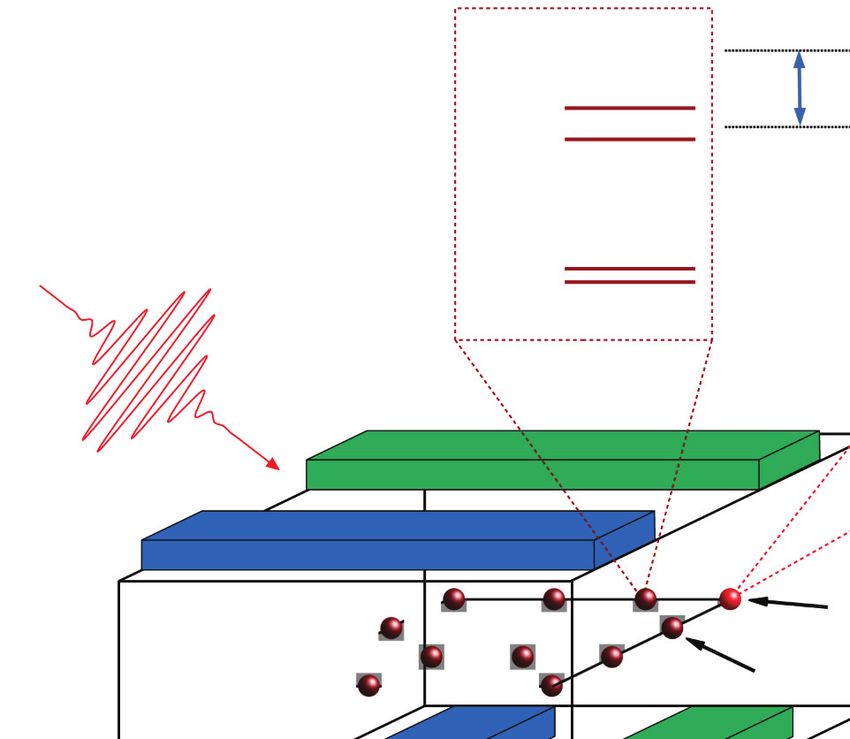
mond [16]. In Fig. 1 we show the basic principle, and
between CF states [1] to 1.3 s for nuclear transitions
the underpinning hierarchy of relevant energy scales is
[2], and even up to six hours by employing dynamical
presented in Fig. 2. By making use of the nontrivial uni-
decoupling [3] have recently been demonstrated.
tary evolution of the active qubits under this Hamiltonian
Furthermore, the possibility to read out single spin states
(i.e., a state-dependent phase accumulation), the full inter-
has been demonstrated using detection of photons emit-
action strength can be exploited to execute the gate. For
ted from yttrium aluminum garnet [4,5], yttrium ortho-
qubits spaced by more than of the order of 1 nm, the gate
vanadate [6], and yttrium orthosilicate [7–9]. Some RE
time is reduced by up to two orders of magnitude as com-
ions exhibit CF transitions in the frequency range used
pared with the dipole-blockade scheme. In contrast to the
in telecommunications, which makes them well suited as
dipole-blockade gate, this faster gate that couples qubits at
quantum repeaters [10,11].
longer ranges requires a precise knowledge of the dipolar
Previous schemes for quantum computing with RE ions
interaction strength.
proposed to use electric dipolar interactions of CF states,
Our quantum computing scheme shares several features
suggesting to realize a controlled NOT (CNOT) gate via
with that proposed by Hill et al. [15] for phosphorus
donors in silicon. As in that proposal, we use nuclear
*
markus.mueller@psi.ch spins as passive qubits, dipole-coupled active qubits, and
essentially the same CNOT implementation. However, our
Published by the American Physical Society under the terms of
the Creative Commons Attribution 4.0 International license. Fur-
scheme has substantial advantages in speed (a factor of
ther distribution of this work must maintain attribution to the 600 faster for single-qubit gates), interaction strength, and
author(s) and the published article’s title, journal citation, and simplicity. There are also schemes that use electric dipolar
DOI. interactions, e.g., between phosphorus donors in silicon;
2691-3399/21/2(1)/010312(19) 010312-1 Published by the American Physical SocietyGRIMM, BECKERT, AEPPLI, and MÜLLER PRX QUANTUM 2, 010312 (2021)
FIG. 2. The optimal level scheme of a Kramers RE ion in a CF
field, showing the energy scales governing Hamiltonian (1). We
use the ground state and one excited spin-orbit manifold, requir-
ing the lowest-lying states of both manifolds to be CF doublets
FIG. 1. Basic principle of the quantum computing scheme. with different anisotropy directions, which we then Zeeman split
The passive (memory) qubit consists of nuclear degrees of free- with an external field. From the ground state doublet we only
dom in the presence of polarized electronic RE spins. Even need the lower Zeeman state. The coupling to a nuclear spin
though the electronic spins create substantial internal fields, they with I = 1/2 splits the electronic states into pairs of hyperfine
are much smaller than the external field, such that the electronic states, where the nuclear spins are either aligned or antialigned
system remains in its gapped, fully polarized ground state and with the electronic spin. The spatial density of the RE ions is
spin flips are suppressed. The nuclear qubits can be selectively adjusted such that the dipolar interactions Jdip have by far the
activated by optical excitation to a (locally tunable) electronic smallest energy scale (apart from the nuclear Zeeman energy).
CF doublet with a large magnetic moment. Two activated qubits An analogous bound applies to the operation temperature T.
communicate via the electronic (magnetic) dipolar interaction,
allowing for fast two-qubit gates over distances of several 10 nm, Kramers RE ions, i.e., ions with an odd number of elec-
as long as the dipolar interaction is sufficiently strong as com- trons and thus halfinteger total angular momentum J , in
pared with the inverse lifetime of the active qubits. This enables a solid-state matrix and subjected to an external magnetic
gates between non-nearest neighbors.
field. The effect of the crystal environment on the RE ions
is captured by the CF potential [19,20]. It breaks the spheri-
cf. Ref. [17]. While similar concepts could be implemented cal symmetry of the isolated ion and splits its (2J + 1)-fold
degenerate J manifold into CF levels, whose degeneracy
with RE ions, we do not pursue this route here.
The paper is organized as follows. In Sec. II we propose and magnetic properties depend on the point symmetry
of the RE site in the crystal. The splitting between dif-
our RE-based qubits and discuss necessary and desirable
CF properties of their host material. We describe how to ferent J manifolds is governed by Hund’s rules and is
typically very large, J /h ∼ 100 THz. Within a given J
carry out fast single-qubit gates in Sec. III. In Sec. IV we
present the core idea: the implementation of a CNOT gate manifold, the single-ion Hamiltonian consists of the CF
potential (HCF ), Zeeman terms (HZ,e + HZ,n ) in the pres-
between RE qubits via magnetic dipolar interactions. A
ence of an external magnetic field B , and the hyperfine
discussion of the DiVincenzo criteria for quantum com-
puting [18], in particular the stability of the qubits that are interaction (HHF ) between the electronic spin, J , and the
not directly addressed in one- and two-qubit operations as nuclear spin, I ,
well as the selective addressability of individual qubits, is
Hsingle (J , I ) = HCF + HZ,e + HZ,n + HHF
given in Appendix C. We compare our scheme with the
CNOT implementation via the dipole blockade and to the = VCF (J ) + gJ μB B
· J
Si:P proposal of Hill et al. [15] in Sec. V. Finally, Sec. VI
· I + AJ J · I .
− gN μN B (1)
contains a case study of erbium-doped Y2 SiO5 as a promis-
ing material for implementing our ideas, and in Sec. VII we
summarize the main results. In Fig. 2 we illustrate the hierarchy of the terms in Hamil-
tonian (1) of the ideal qubit setup. The CF potential VCF (J )
induces the largest splitting within a given J manifold,
II. SETUP AND HAMILTONIAN typically of the order of hundreds of gigahertz up to sev-
eral terahertz. The electronic Zeeman term with the Landé
A. Hamiltonian factor gJ lifts the degeneracy of time-reversal-symmetry-
To realize qubits, we use the hyperfine states of single protected Kramers doublets. It induces a splitting linear
010312-2UNIVERSAL QUANTUM COMPUTING USING ELECTRONUCLEAR... PRX QUANTUM 2, 010312 (2021)
in the field, of the order of about 2μB /h ≈ 30 GHz/T. B. Active and passive qubits: an ideal RE system
These two terms determine the electronic level structure, The optimal CF level structure for our qubit scheme
which we use to coherently manipulate the electronic is shown in Fig. 2. The level and qubit structure is cho-
wavefunctions of the RE ions. sen such as to maximize life and coherence times, while
The hyperfine interactions with the nuclear spin I are minimizing single-qubit and two-qubit gate times.
usually well captured by a contact interaction of the form To achieve long coherence times, we store the quan-
J · I with the hyperfine constant AJ ; typically, AJ /h is of tum information in the nuclear spin states (|+n , |−n ) on
the order of gigahertz. This interaction is used to transfer Kramers RE ions, whose electron shell is in its ground
quantum information from nuclear to electronic degrees state. These nuclear states serve as memory or “passive”
of freedom, and back. Since the hyperfine interaction is qubits. We denote their states as |0pas and |1pas , respec-
much smaller than the electronic Zeeman splitting, its main tively. Given the small magnetic moments of the nuclear
effect is to (anti)align the nuclear spins with the polar- spins, they hardly interact with each other. Moreover, they
ized magnetic moments of the electronic doublet states. In couple to phonons only very weakly (indirectly via the
the theoretical discussion of this paper, for simplicity, we electrons), so their coherence time is much larger than
assume the nuclear spin to be I = 1/2, but similar reason- that of electronic states. Coherence times of such hyper-
ings and results apply to larger nuclear spins, for example, fine states of up to six hours have been measured in RE
in the showcase material Er3+ :Y2 SiO5 with I = 7/2. systems [3].
The last relevant energy scale is the (magnetic) dipole For the electronic dipolar interaction (2) not to entangle
interaction between RE ions. We make use of the inter- the passive qubits, we require a nondegenerate electronic
action between excited electronic states to build a gate ground state |GSe [21], which is achieved by polariz-
between two qubits located at a finite spatial distance. A ing electronic doublets with a magnetic field. We further
system of two active qubits is governed by two single-ion assume that all RE ions can be cooled efficiently (e.g.,
Hamiltonians as in Eq. (1), and by the magnetic dipolar by pumping schemes involving higher excited CF states,
interaction between the RE electrons as demonstrated in Refs. [2,6,22,23]) to occupy that state.
(i)
α,β
Because of the relative smallness of the dipolar interac-
H= Hsingle + Jdip Jα(1) Jβ(2) , (2) tion compared with the Zeeman splitting (provided that
i=1,2 α,β the RE ions are far enough apart in the host medium,
Jdip /(μB B) ∼ 10−6 for distances r = 10 nm and B = 1 T),
with the dipolar coupling we can neglect dipole-induced spin-flip terms in the elec-
tronic ground state. This effectively “switches off” the
electronic interaction between the passive qubits [24].
α,β μ0 (μB gJ )2 3r12,α r12,β
Jdip = δα,β − . (3) Since the passive qubits are well protected on the
4π r312 r212 timescales discussed above, their quantum information
needs to be transferred to “active” qubits before one can
Here the superscripts 1 and 2 label the two RE ions, while implement efficient quantum gates on them. A natural can-
r12,α (α = x, y, z) are the Cartesian components of the vec- didate for an active qubit is a doublet of excited CF states,
tor r12 connecting the locations of the two qubits in the which we denote by |↑e ,|↓e . In general, these have siz-
lattice. In the following, we always assume the dipole able magnetic moments of a few μB , which allow them to
interaction to be much smaller than the hyperfine split- interact with other active qubits through dipolar coupling.
ting, which is the case for qubit distances exceeding r The hyperfine interaction with the nuclear spin splits each
[μ0 μ2B /(4π AJ )]1/3 ∼ 2 Å. of these CF states into a pair of hyperfine states, similarly
Because of the tiny nuclear moment μN , the nuclear as in the passive ground state. One level of either hyper-
Zeeman term and dipolar interactions involving nuclear fine pair is selected to represent one of the two active qubit
spins have much smaller energy scales. For our scheme, states |0act and |1act . To limit decay processes, it is best
the Zeeman term only plays an indirect role, insofar as to choose the qubit state |0act as the lowest of the four
it increases the fidelity of our two-qubit gate by tuning hyperfine states. This leaves us with two choices of how
off resonance a class of undesired higher-order spin-flip to assign the other qubit state |1act to either of the two
processes that could occur while carrying out the gate hyperfine levels of the higher-lying Zeeman state. Accord-
operation. The effects of dipolar interactions between elec- ingly, we distinguish between an electronuclear qubit and
tronic and nuclear spins is analyzed in Appendix C 3, a purely electronic qubit, respectively, referring to the
where we conclude that they are negligible. The purely degrees of freedom in which the two qubit states differ; see
nuclear dipole interactions create entanglement between Fig. 3. The choice of the optimal active qubit with respect
the nuclear spin qubits on a timescale corresponding to to the CNOT gate fidelity is discussed in Sec. IV.
(μB /μN )2 ∼ 106 two-qubit operations, which constitutes It is advantageous to further require that the dou-
an intrinsic decoherence time of the qubits. blets of electronic ground and excited states come with
010312-3GRIMM, BECKERT, AEPPLI, and MÜLLER PRX QUANTUM 2, 010312 (2021)
(a) To achieve long lifetimes of the active qubits, the active
excited doublet should be the lowest CF level of a higher-
Active qubit
lying J manifold, whose gap to lower J manifolds is
significantly larger than the Debye frequency. Under these
conditions, the active qubit state |0act can only decay via
multiphonon emission or slow photon emission [28]. The
decay rate of the excited Zeeman state due to phonon
emission is generally very small as well, since the Debye
density of states at the frequency of the Zeeman splitting is
tiny. Indeed, lifetimes as long as 60 s have been reported,
e.g., in (the ground state doublet of) erbium-doped Y2 SiO5
(b) [29].
To activate qubits (i.e., to transfer the quantum wave-
Active qubit
function from a nuclear spin to electronic degrees of
freedom), one can use laser pulses that are resonant with
specific transitions in the level scheme shown in Fig. 3.
By coupling to the transition dipole moments between
CF states, one can coherently manipulate their popula-
tions via Rabi oscillations, as demonstrated, for example,
in Refs. [1,2,30,31].
FIG. 3. Two possible choices for the mapping between passive III. SINGLE-QUBIT GATES
and active qubits: (a) electronuclear qubit and (b) purely elec-
tronic qubit. Activation of a qubit is achieved by two π pulses as A. Implementation of single-qubit gates
discussed in the main text. Each pulse leaves one hyperfine state
Single-qubit gates on passive qubits could be imple-
of the passive qubit untouched and takes the other state into one
of two target hyperfine states within the excited electronic dou- mented by coupling directly to the nuclear spins with
blet. These two states constitute the active qubit. The two target microwaves, which drive Rabi oscillations within the pair
states have opposite (electronic) magnetic moments, and thus the of hyperfine states constituting the passive qubit. How-
active qubits can interact over a long distance. ever, this has the severe drawback that the coupling to the
nuclear moment is very weak, which implies very long
different g-factor anisotropy and therefore favor different gate times of the order of t ∼ /(μN Bac ) = 21 μs (for
magnetization directions. This excludes implementations an amplitude of the driving field of Bac = 1mT). Similar
with cubic point symmetries at the RE site. The different qubit proposals based on phosphorus donors in silicon as
anisotropies help to reduce the single-qubit gate time by in Refs. [15,32] suffer from this problem [33].
allowing for an efficient implementation of nuclear spin Here we present a much faster alternative, which takes
flips in the ground state by driving optical transitions via advantage of the nonparallel magnetic polarizations in
the excited doublet states since there is significant overlap ground and excited electronic doublet states. The latter
between all nuclear spin states in the ground and excited implies that the nuclear spin is not conserved upon switch-
doublets. Vastly different anisotropies are unusual, and a ing between ground and excited electronic states. This
vanishing perpendicular g factor g⊥ [25] requires spe- allows us to drive transitions between the passive qubit
cial symmetries at the RE sites: tetragonal symmetry with levels by passing via excited doublet states, which merely
J = 3/2, or trigonal or hexagonal symmetry with J > 1/2; requires coupling to the electronic degrees of freedom. For
see Table I in Appendix D for more details on the symme- example, an X gate, i.e., a logical spin flip, is achieved
try constraints. Nonetheless, as long as the anisotropies of with three consecutive laser pulses, as sketched in Fig. 4.
the ground and excited state doublets differ sufficiently, one In this scheme, the gate time is limited by the inverse of
can carry out fast single-qubit gates. the electronic matrix elements, which are typically much
Finite perpendicular g factors cannot occur for non- larger than the Zeeman coupling to the nuclear moments.
Kramers doublets. Thus, it is impossible to obtain non- The speedup of this method depends on selection rules,
parallel magnetization directions for different doublets in which involve the value of J in the ground and excited
these systems [26]. We therefore restrict ourselves to doublet states. The largest speedup is achieved if mag-
Kramers ions. To electrically gate such Kramers ions, netic dipole transitions are allowed between the ground
as discussed in the Appendix C2, one needs a material and excited J manifolds, i.e., if J = 0, ±1 [34]. As com-
where the RE site does not contain an inversion symme- pared with the direct manipulation of the nuclear spin, one
try such that all CF states have a finite electrical dipole achieves speedup by a factor of the order of μB /(3μN ) =
moment [27]. 600 [35]. The corresponding gate time is of the order of
010312-4UNIVERSAL QUANTUM COMPUTING USING ELECTRONUCLEAR... PRX QUANTUM 2, 010312 (2021)
(a)
(b)
FIG. 4. Implementation of a fast X gate via an excited state.
The blue arrows denote π pulses that switch the population of
the states they connect. The pulses are applied in the order of
the indicated numbers. The differing g-factor anisotropies in the FIG. 5. Two possible active qubit choices that are found by
ground and excited doublets ensure sizable matrix elements for minimizing the number of resonant channels and maximizing
all three transitions. the lifetime of the active qubits: (a) the electronuclear qubit
and (b) the electronic qubit. We use here the same level struc-
ture as for the excited doublet in Fig. 3, with the indices 1 and
t ∼ 3/(μB Bac ) = 35 ns for an amplitude of the laser field 2 labeling the two ions on which the CNOT gate acts. The red
of Bac = 1 mT. This concept of nonparallel g factors in dif- arrows denote the electronuclear and electronic “spin flip-flop”
ferent CF doublets has been used in, e.g., Refs. [1,2,30] in matrix elements for (a) and (b), respectively. Such a simultane-
order to measure spin-echo coherence times. ous swap of both RE qubits is exactly resonant. The blue and
green arrows in (b) denote the nuclear and electronuclear flip-
IV. TWO-QUBIT OPERATIONS flops, respectively, which are nearly resonant up to the nuclear
Zeeman energy. These processes limit the fidelity of the CNOT
A. Implementation of a CNOT gate gate in the most favorable case of active qubits with g⊥ = 0,
for which the electronic qubit (b) minimizes the gate error. In
To achieve universal quantum computing, one needs
most host materials g⊥ is nonzero and the electronuclear qubit
gates that entangle two qubits [18,36]. We show here an (a) should be used.
implementation of a logical CNOT gate that follows a simi-
lar scheme proposed in Refs. [15,32]. The CNOT gate flips
the target qubit if and only if the control qubit is in state to transverse interaction terms are addressed in the next
|1. subsection.
Before carrying out a two-qubit gate operation, we need Using the Ising interaction (4) in conjunction with
to activate the two passive qubits by two π pulses, as single-qubit gates, one can implement a CNOT gate on two
illustrated in Fig. 3. Since the pair of active moments is active qubits as [37]
no longer fully polarized (unlike in the passive ground √ √ †√ √
state) but in a superposition of different polarization states, CNOT = Z 1 Z 2 X 2 C(π/2) Y2 . (5)
the dipolar interaction entangles the qubits by inducing
a configuration-dependent phase. In order to avoid reso- √
Here α i (α = X , Y, Z) denotes a π/2 rotation of qubit i
nances due to flip-flops, i.e., the simultaneous flipping of √ (i)
around the axis α, i.e., α i = e−i(π/4)σα , and C(π/2) =
(electronic and/or nuclear) spins on both RE ions, both 1 2
active qubits are chosen of the same type (‘electronu- e−i(π/4)σz σz is implemented by unitary time evolution
clear’, or, for g⊥ = 0, ‘electronic’); see Fig. 5 and the next under the Ising interaction for a time tCNOT = π/(4Jdip ),
subsection. which is approximately the gate time of the two-qubit gate.
Upon projection onto the active qubit subspace, the However, the full Hamiltonian (2) does not only consist of
dipole interaction between two active qubits reduces to an this Ising interaction, but contains additional terms, namely
Ising-like interaction the single-ion Zeeman and hyperfine interactions in Eq. (1)
as well as those two-qubit interactions that are non-Ising.
Even with such terms present, we can reproduce an effec-
μ0 (μB g /2)2 3(r12 · m̂)2
Hdip ≈ 1− σz(1) σz(2) tive C(π/2) operation by eliminating their effect with a
4π r312 r212
spin echo, namely,
≡ Jdip σz(1) σz(2) , (4)
C(π/2) = X1 X2 e−iHdip tCNOT /2 X2 X1 e−iHdip tCNOT /2 . (6)
where m̂ denotes the direction of the magnetic moment in
the excited doublet and σz is the Pauli matrix acting in the Here it is assumed that the X gates are much faster than
eigenbasis of an active qubit. The small corrections due tCNOT and thus can be approximated as instantaneous. After
010312-5GRIMM, BECKERT, AEPPLI, and MÜLLER PRX QUANTUM 2, 010312 (2021)
completing a CNOT operation, the quantum information is smaller than the intrinsic fidelity for the case g⊥ = 0, it is
transferred from active back to passive qubits, analogous still reasonably small.
to the activation. Since the spin-flip errors are rather small, the two most
Note that the interaction of active qubits with all other important error sources in an experimental setting are most
(passive) qubits is small: because of the applied spin echo likely rather (i) the coherence time (T2 ) of active qubits,
in the scheme above, the longitudinal part of the dipolar and (ii) the finite time (tact ) to activate the qubits and for
field (with respect to m̂) created by passive qubits cancels the spin-echo pulse. These impose a lower bound on the
out for the active qubit. The dephasing effect of the trans- typical error
verse part is negligible since the dipolar interaction is much
smaller than the Zeeman energy, as discussed in more tCNOT tact 2
detail in Appendix C 3. As a consequence, the activated 1 − F max , , (7)
T2 tCNOT
qubits effectively only talk to each other.
with the two-qubit gate time tCNOT . Both tact and tCNOT , and
thus both of these lower bounds, can be tuned within some
B. Fidelity of the CNOT gate range by the angle of the applied magnetic field. On the one
Let us consider the fidelity of our CNOT implementation. hand, the orientation of the field determines the overlap
So far we have neglected the transverse (non-Ising) parts of between nuclear spin states in the active and passive qubits
the hyperfine and dipolar interactions, that is, those terms and thereby the single-qubit gate time. On the other hand,
that flip one or both (electronic or nuclear) spins within the field direction also determines the magnetic moment
the excited doublet states. This is motivated by the fact μ
m of the Zeeman-split active qubit states, 2μm /μB =
that if we choose to use active electronuclear qubits (and [g sin(θ)]2 + [g⊥ cos(θ)]2 , and thereby affects the dipo-
also for electronic qubits, if we assume that g⊥ = 0), spin- lar interaction strength and thus the two-qubit gate time.
flip terms appear only in higher-order perturbation theory The orientation of the magnetic field should be chosen such
in the transverse terms in Hamiltonian (2). Nevertheless, as to minimize these errors.
such transverse perturbations can become important if they
connect states that are close in energy. V. COMPARISON WITH SIMILAR SCHEMES
In order to minimize the number of such resonant matrix
elements, one should realize the active qubits of the same A. Comparison with CNOT implementation via dipole
type (“electronic” or “electronuclear”) on the two con- blockade
cerned ions; see Fig. 5. Indeed, this leaves only one We now compare our scheme with alternative imple-
residual resonant process that has an initial state in the two- mentations of CNOT gates with dipole-coupled RE ions.
qubit subspace. The optimal choice, as well as the resulting References [12–14] proposed to use the so-called dipole
fidelity, depend on whether or not the transverse g factor of blockade. Here the qubits consist either of two electronic
the excited doublet vanishes. If g⊥ = 0, there are no resid- CF states or of two hyperfine levels of a single electronic
ual interactions that act directly within the excited doublet. level. An auxiliary state, to which one qubit state can be
Any non-Ising matrix elements are thus due to tunneling excited, is needed as well. All these states interact via
through intermediate, higher-lying CF states. This reduces their magnetic or electronic dipole moments. For RE ions,
the magnitude of residual matrix elements and therefore magnetic and electric dipolar interactions are usually of
leads to a high fidelity of our CNOT implementation. Typi- similar strength, since the electric dipole moments are typi-
cally, the electronic active qubit is the better choice in this cally very small, while typical magnetic moments are fairly
case. The intrinsic gate error due to the non-Ising terms large.
is then limited by the off-resonant nuclear or electronu- The dipole blockade works as follows. If the control
clear “spin flip-flops”; see Fig. 5(b). It can be estimated qubit is in state |0, it is transferred to an excited state
to be negligibly small, 1 − Fmin ∼ 10−14 for a distance with different dipole moment. Through its dipolar interac-
of r = 10 nm between the qubits, as we show in detail in tion with the target qubit, the level structure of the latter
Appendix B 3. is changed. Now a sequence of three pulses, whose fre-
In the case of a finite g⊥ , the purely electronic active quencies match the unmodified level structure of the target
qubit is ruled out, since the transverse part of the dipole qubit, is applied. This swaps states |0 and |1 of the target
interaction mediates a resonant electronic flip-flop pro- qubit, but only if the control qubit is left in state |1, since
cess with matrix element V ∝ (g⊥ /g )Jdip , which leads the pulse sequence is off-resonant if the control qubit is
to a substantial gate error 1 − Fmin = O[(g⊥ /g )2 ]. How- excited; see Fig. 6. After this conditional swap, the control
ever, the electronuclear qubit is still viable. The gate error qubit is brought back to its initial state.
due to the residual interactions can then be estimated to Such a dipole blockade could also be implemented with
be 1 − Fmin ∼ 10−5 for a distance of r = 10 nm between our magnetic states, and it is thus interesting to com-
the qubits; see Appendix B 3. While this is substantially pare it with our proposed scheme. We consider the regime
010312-6UNIVERSAL QUANTUM COMPUTING USING ELECTRONUCLEAR... PRX QUANTUM 2, 010312 (2021)
140
120
100
gate
80
db /t
tgate
60
40
FIG. 6. Pulse sequence for the dipole-blockade scheme. If the 20
control qubit is in state |0, it is excited, which shifts the levels
of the target qubit out of resonance with the swapping pulses. A 10–12 10–10 10–8 10–6 10–4 10–2
swap is thus only carried out if the control qubit is in state |1. Gate error 1 – F
The indices “ctrl” and “tar” denote the control and target qubits,
respectively.
FIG. 7. The speedup factor tdb gate /tgate by which the gate time
of our CNOT implementation is reduced as compared with that
of a dipole-blockade scheme carried out with Gaussian pulses
where the dipolar interaction is much smaller than the (assuming that the dipolar interaction is smaller than the hyper-
experimentally achievable Rabi frequencies, such that our fine splitting and the largest achievable Rabi frequencies). The
scheme can be applied (while in the opposite limit only speedup increases logarithmically with the maximally admissible
the dipole blockade can be used). This is the regime gate error 1 − F that we assume to be given by the probabil-
of qubit distances beyond r [μ0 μB /(4π Bac )]1/3 ≈ 1 nm ity of a nonresonant excitation (rather than by the decoherence
(with Bac = 1 mT). Here our CNOT implementation is sig- time of the qubits). The oscillatory behavior traces back to Rabi
oscillations in the unwanted transition probability.
nificantly faster, since, being based on the state-dependent
phase accumulation, it makes use of the full interaction
strength between two RE ions, achieving a gate time equal We note that a CNOT gate speedup implies that the gate
to tCNOT ≈ π/(4Jdip ). Thereby the interaction strength error due to the finite decoherence time in Eq. (7) is smaller
needs to be known precisely, and the gate duration has to by the same factor in our scheme as compared with the
be adjusted accordingly. The dipole blockade instead relies dipole blockade. This allows for the entanglement of qubits
on the ability to resolve the frequency shift induced by the at longer distances with better (coherence-limited) fidelity
dipole interaction. This requires Rabi frequencies smaller in our scheme. On the other hand, the dipole blockade has
than the interaction strength and consequently gate times the advantage that it can also be used in the regime where
that are substantially longer than in our scheme. We esti- the dipolar interaction is larger than the hyperfine split-
mate the gate time of the dipole blockade in Appendix A ting. Thus, for very close-by qubits (r 1 nm), the dipole
by minimizing the π -pulse duration for a fixed fidelity blockade is the faster gate. If such neighbors could be
goal. We numerically evaluated the unitary time evolution addressed individually (by magnetic adatoms or gating) in
in the rotating-wave approximation and optimized with an experimental setting, an approach that combines dipole
respect to both the pulse cutoff Tcut and the Gaussian pulse blockade and the scheme presented here might be used to
width T, such that, for all detunings larger than Jdip , the entangle close and distant pairs of qubits, respectively.
gate error is below a threshold value 1 − F . Like for our Note that the dipole blockade does not require precise
direct gate, the gate time of the dipole blockade is propor- knowledge of the dipolar interaction strength, as long as
tional to /Jdip , but, in addition, it grows logarithmically it is large enough. In contrast, our two-qubit gate does
with the desired gate fidelity; see Fig. 7. Therefore, if require that knowledge. This is, however, not a substantial
one requires gate errors to be less than 10−4 , the indirect drawback, since the interaction depends only on the atomic
dipole blockade is a factor of roughly 50 slower than our positions in the crystal, which are very stable over time. It
gate. thus suffices to initially characterize the interactions with
In Fig. 7 we show that the minimal gate time required a precision higher than the desired gate fidelity, so as to
in the dipole blockade increases monotonically with the ensure precise gates with well-timed pulse sequences.
required fidelity, but does so in an oscillatory manner. This
originates from Rabi-like oscillations of the (unwanted)
transition probability, which in turn result from the nonadi- B. Comparison with implementation with phosphorus
abatic switching on and off of the pulses at t = ±Tcut ; see donors in silicon
Appendix A for a detailed calculation. Viewing the fidelity Our scheme resembles in several aspects that proposed
as a function of the π -pulse duration Tπ = 2Tcut , the local for phosphorus donors in Ref. [15], where the nuclear spins
maxima of the fidelity are spaced by Tπ = 4π/ωdip . of 31 P+ are used to store quantum information. In contrast
010312-7GRIMM, BECKERT, AEPPLI, and MÜLLER PRX QUANTUM 2, 010312 (2021)
to our scheme, the donors have no electronic spin. Instead, for qubit spacings r = 10 nm. This leads to a coherence-
they are tunnel coupled to single-electron transistor struc- time-limited gate fidelity of the CNOT implementation, with
tures. By gating these, an extra electron is loaded into a Fmin ≈ 99.9% and a total gate time of 4.2 μs. A fidelity of
spin-down state onto the donor. This operation is equiv- above 99% can be achieved for a range of qubit distances
alent to our gate tuning the RE qubits by a local Stark r, which allows us to directly entangle qubits beyond the
shift, which singles out the qubits that are later selec- nearest-neighbor distance.
tively addressed. In the proposal of Ref. [15], resonant This theoretical fidelity is already above the threshold
microwave pulses then transfer the stored quantum infor- for quantum error correction. If even higher fidelities are
mation from the nuclear spins to the electronic states. This desired, faster single-qubit gates (stronger pulses) and/or
is the analog of the activation step of our electronic qubits. longer decoherence times are needed. To improve the lat-
Two active qubits interact by dipolar interactions, and the ter, one could try to decouple the electronic spins from the
CNOT gate is realized in a similar way as we discuss in this surrounding nuclear spins sitting on other (non-RE) atoms.
paper. In comparison with donors in silicon, our scheme This can be achieved via dynamical decoupling and/or
has several advantages. (i) The magnetic moment of (effec- by choosing a host material where the non-RE ions have
tive) RE spins are much larger (typically, by a factor of smaller or even vanishing magnetic moments.
5–7) than those of single electrons. This allows for a much The above fidelity estimation shows that Y2 SiO5 is a
shorter two-qubit gate time, which is inversely propor- very good host system. It might also be an interesting can-
tional to the square of the magnetic moment entering the didate when doped with other RE ions such as Nd3+ [40]
dipole interaction. (ii) Our single-qubit gate time is up to or Yb3+ [41]. Another interesting host system to explore
approximately 600 times faster since we can make use of is isotopically enriched silicon, where decoherence due
the hyperfine interaction and manipulate the nuclear spin to nuclear spins is minimized. However, for that mate-
states via electronic transitions instead of coupling electro- rial, we currently do not have precise g-tensor values and
magnetic pulses directly to the nuclear spins. (iii) The qubit coherence time measurements.
activation in our scheme is simpler and does not involve
a charge transfer over interatomic distances (with associ-
VII. CONCLUSION
ated dipole moments and the danger of exciting the lattice).
This is likely to reduce the activation error. In this paper we have proposed an implementation of
qubits using RE ions subject to a CF and hyperfine cou-
pling. Our scheme constitutes a promising platform for
universal quantum computing. We use nearly decoupled
VI. CASE STUDY OF Er3+ :Y2 SiO5
passive (memory) qubits and transfer them to less pro-
To illustrate our scheme and the main ideas of this paper, tected active qubits only when they are involved in a two-
we discuss a specific RE material: 167 Er-doped Y2 SiO5 , qubit gate. The passive qubits are well-protected nuclear
Er being a Kramers ion with nuclear spin I = 7/2.
167 3+
spin states serving as quantum memory. The active qubit
There are two inequivalent Er sites each with C1 symmetry. states are magnetized electronic states that can interact
The absence of inversion symmetry allows for electrical over relatively long distances.
gating of the qubits. For simplicity, we discuss only Er site The central idea of this paper is to implement a CNOT
1 (using the notation of Ref. [38]). Similar results hold for gate based on the phase accumulation due to the Ising-like
site 2 as well. A detailed evaluation with all the experimen- dipole interaction between two active qubits. This achieves
tally measured parameters can be found in Appendix E. a speedup by up to two orders of magnitude as compared
Here we summarize the main results. with the standard dipole blockade, in the regime where
We choose the active qubit to be of electronuclear type, dipolar interactions are weak as compared with typical
consisting of the lowest and second-highest hyperfine lev- optical Rabi frequencies and the hyperfine splitting (i.e.,
els of the excited doublet, i.e., the states with nuclear spin for qubits spaced by more than of the order of 1 nm).
projections −7/2 and −5/2 with respect to the polarization The level scheme of a single ion (illustrated in Fig. 2)
axis of the excited doublet. The latter is the lowest CF level should have the following essential ingredients: (i) a
in the first excited manifold J = 13/2, accessible with the Zeeman-split magnetic ground state; (ii) a nuclear spin
convenient optical transition wavelength 1536.5 nm. The and strong hyperfine interactions; (iii) a doublet state at
finite coherence time T2 of the excited states has been mea- the bottom of an excited J manifold, having a magnetic
sured to be as long as T2 = 4.4 ms [31] for sufficiently low anisotropy differing from that of the ground state. The last
temperatures and large magnetic fields [39]. requirement can only be met with Kramers RE ions with
The direction of the externally applied magnetic field noncubic point symmetry groups. Our estimation of gate
is still a further parameter to tune the single- and two- errors due to residual (non-Ising) interactions suggest that
qubit gate times, as discussed in Sec. IV B. We optimize it typically the two-qubit gate fidelity is limited by the coher-
numerically in order to achieve the best two-qubit fidelities ence time T2 of the active qubit. Using a crystal where
010312-8UNIVERSAL QUANTUM COMPUTING USING ELECTRONUCLEAR... PRX QUANTUM 2, 010312 (2021)
the RE site has no inversion symmetry generally allows typical hyperfine splittings of RE ions. It is also much
for electrical gating of the qubits and thereby assures that smaller than the highest experimentally achievable Rabi
individual qubits can be addressed selectively. frequencies for electric dipole transitions. This implies that
As a concrete example and illustration of our scheme, it is the smallness of the dipolar shift in the spectrum that
we have discussed the case of Er-doped Y2 SiO5 . However, limits the gating time. Indeed, if the swapping operation
the scheme proposed here equally applies to molecular on the target qubit is to take place only if the control qubit
magnets and crystals hosting transition metal ions, as long is in state |1, the Rabi frequency of the three pulses used
as they generate a CF level structure that matches the above to swap the target qubit must be significantly smaller than
three criteria. Given the possibilities offered by isotope the dipolar shift. In our implementation, the gating time
enrichment and semiconductor processing, we believe sil- is instead limited by the time evolution under the mag-
icon doped with RE ions [42,43] to be a very promising netic dipole interaction, leading to a gate time of tCNOT ≈
platform. π/(4Jdip ), where the dipolar interaction strength is com-
In summary, we propose the implementation of RE parable with the dipole energy shift above ωdip ∼ Jdip /.
qubits with coupled electronuclear degrees of freedom and The advantage of our scheme is that the system entangle-
fast single-qubit and CNOT gates that can entangle not ment follows directly from the dynamics governed by this
only nearest neighbors, but also relatively distant qubits Hamiltonian. Below we estimate the speedup of our imple-
in an array. Combined with the readout capability of sin- mentation compared with the dipole-blockade scheme with
gle ions and the possibility of coupling RE ions to optical Gaussian pulses.
modes, networks of such ions are promising candidates for
scalable quantum computing. 1. Dipole blockade with Gaussian pulses
To estimate the gate time of the dipole-blockade
ACKNOWLEDGMENTS
scheme, we use Gaussian pulses (with cutoffs), since they
The authors would like to thank A. Grimm for use- drive the desired transition more selectively than other
ful comments on the manuscript. This work is supported pulse shapes [37]. The temporal envelope of the pulse is
2 2
by the Swiss National Science Foundation (SNSF) under described by (t) = 0 e−t /T θ (Tcut − |t|), where 0 is
Grant No. 200021_166271. the Rabi frequency corresponding to the maximal ampli-
tude at time t = 0 and T is the pulse width. The latter is not
APPENDIX A: COMPARING DIRECT DIPOLE to be confused with the pulse duration equal to Tπ = 2Tcut .
INTERACTION VERSUS DIPOLE BLOCKADE AS Our goal is to optimize the two parameters Tcut and 0 such
CNOT IMPLEMENTATIONS as to minimize the π -pulse duration for a given desired
CNOT gate fidelity F and dipolar frequency shift ωdip =
We compare the CNOT gate time of our implementation
with the gate time of the dipole blockade as explained in Jdip /. Note that, since the pulse should carry out a π rota-
Sec. V A of the main text; see Fig. 6 therein. tion on the resonant state (ω = 0), the pulse width T is
First let us discuss the magnitudes of the magnetic and not a free parameter, but depends on Tcut and 0 , as shown
electric dipolar interactions. As mentioned in the main text, below.
the 4f configurations of RE ions have fairly small elec- For simplicity, we consider a two-level system, with one
tric dipole moments. On the other hand, one can have state being the addressed qubit state and the other state
large magnetic moments that compensate for the weaker being the excited ancillary state. The unaddressed qubit
magnetic interaction. As a consequence, it turns out that state as well as all other CF states are neglected, as they
the magnetic and electric dipole interactions are typically are assumed to be far off resonance. The Hamiltonian of
comparable in magnitude. For example, in the material this two-level system in the rotating frame of the pulse
Eu3+ :Y2 SiO5 , proposed in Ref. [14] as a candidate mate- frequency and with the rotating-wave approximation is
rial for quantum computing, the electric dipole moments [44]
of ground and excited manifolds differ by μe = 7.7 ×
ω 0 −(t/T)2
10−32 C m. Typical (differences of) dipole moments are H RWA = σz + e θ (Tcut − |t|)σx
smaller than this value, but of a similar order of magnitude. 2 2
A magnetic moment of only μm = 2.5μB of the dou- ≡ H0 + V(t), (A1)
blet states leads to the same interaction strength between
the two active qubits, assuming vacuum permittivity, i.e., where ω is the detuning between the transition and
μ2e / 0 ≈ μ2m /μ0 . pulse frequencies. In the dipole-blockade scheme ω
For a distance r12 = 10 nm between qubits 1 and 2, corresponds to the dipolar interaction ω/2 = Jdip /.
the electric dipole shift between RE ions is ωdip ∼ We first derive the pulse width T as a function of 0
(μe )2 /(4 0 π r312 ). This evaluates to ωdip = 2π × and Tcut . The Gaussian pulse should carry out a π rota-
80 kHz/[(r12 /10 nm)3 ], which is much smaller than the tion on the resonant state (ω = 0). Because Hamiltonian
010312-9GRIMM, BECKERT, AEPPLI, and MÜLLER PRX QUANTUM 2, 010312 (2021)
(A1) commutes with itself at different times for ω = 0, i Tcut
the pulse width is determined from the condition on the =1− dteiH0 t/ V(t)e−iH0 t/ + O(V2 )
+Tcut
−Tcut
action integral −Tcut dt V(t) = π/2σx . We find that
√ 0 T −(ωT/2)2 Tcut iω T
≈ 1−i π e Re erf − σx ,
√ 2 T 2
π
T= , (A2) (A3)
0 erf(Tcut /T)
where T is the time-ordering operator. The second term in
−1/2
x −t2
where erf(x) = (π ) −x dt e denotes the error func- the last line (as well as the neglected higher-order terms)
tion. are expected to be small for ωT/2 1. In this limit, we
We minimize the π -pulse duration Tπ = 2Tcut numeri- can expand the error function for large absolute values of
cally by simulating the unitary time evolution with Hamil- the argument and find the fidelity Fπ of a single π pulse as
tonian (A1) for fixed 0 and varying Tcut and ω. We then
determine the minimal pulse duration Tπ as follows. For 1 − Fπ = 1 − U 2
each Tcut , we find the smallest detuning ω such that, for 2 2
π −y 2 e−x
all larger detunings, the gate error is below some desired ≈ e −√ [x cos(2xy)
threshold. From this we deduce the minimal Tcut in units 2erf(x) π (x2 + y 2 )
of 1/ω. The result is shown in Fig. 8, where we plot the 2
maximal error 1 − Fπ of the optimized pulse as a function − y sin(2xy)] , (A4)
of its duration. For truncated Gaussian pulses, we find that
Tπ grows logarithmically with (1 − Fπ )−1 and exhibits
where x ≡ Tcut /T and y ≡ ωT/2 are the real and imag-
4π/ω periodic oscillations in log(1 − Fπ ).
inary parts of the argument of the error function, respec-
To understand this result, we use first-order time-
tively. Our aim is to minimize the pulse time Tπ = 2 Tcut =
dependent perturbation theory and estimate the small spin-
4xy under the constraint of a fixed error rate 1 − Fπ . For
flip probability on a state with given detuning ω. For
the optimal pulse, x and y will both be large and relatively
the following calculations, we assume a large detuning
close to each other. Thus, due to the exponential factors
ω 0 , as otherwise the spin-flip probability is non-
in Eq. (A4), x and
y scale to leading order with the large
negligible. Using the interaction picture formalism, the
parameter S ≡ log[1/(1 − Fπ )]/2. Expanding both in
time-evolution operator is expressed as
S, i.e., making the ansatz x = S − log(S)/(2S) + α/S and
y = S + β/S, α and β have to satisfy
U(Tcut , −Tcut )
π −4(α+β) 2β
i Tcut
iH0 t/ −iH0 t/ e (e cos[log(1 − Fπ )] + sin[log(1 − Fπ )]
= T exp − dte V(t)e 16
−Tcut (A5)
√ 2α 2
− 2 πe ) − 1 ≈ 0,
First-order pert. theory
10–2 to leading order in S. The gate time follows as
First-order pert. theory (fit)
Full unitary evolution
10–4
Pulse error 1 – Fπ
Full unitary evolution (fit) Tπ ω = 4xy
10–6
1 1 1
≈ 2 log − log log
10–8 1 − Fπ 2 1 − Fπ
10–10 + 4(α + β). (A6)
10–12 With this we reproduce the aforementioned scaling Tπ ∼
2 log[1/(1 − Fπ )]. Now α + β has to be minimized sub-
0 5 10 15 20 25
Pulse time [π/w]
ject to constraint (A5), which yields a term that periodi-
cally oscillates with log[1/(1 − Fπ )]. This reflects Rabi-
FIG. 8. The maximal error of an optimized π pulse with trun- like oscillations of the transition probability as Tcut ω
cated Gaussian envelope as a function of the pulse time Tπ = increases by multiples of 2π , which results in oscillations
2Tcut is plotted for a fixed dipolar coupling ω. The error with 4π/ω periodicity in Tπ . The numerically evaluated
decreases exponentially with the pulse time on top of which there maximal gate error as a function of the pulse time is shown
are Rabi-like oscillations with period 4π/ω. The fits to the in Fig. 8 for both the first-order expression (A3) and the
numerically optimized pulse times are of the form (A7). full unitary time evolution. The first-order result exhibits
010312-10UNIVERSAL QUANTUM COMPUTING USING ELECTRONUCLEAR... PRX QUANTUM 2, 010312 (2021)
the expected slope Tπ ω ≈ 2 log[1/(1 − F )]. We demon- A further source of gate errors is the population transfer
strate this by fitting a curve of the following form to the of the addressed qubit to (or from) a nontargeted hyperfine
numerical result: state on the same ion. To ensure that the single-qubit opera-
tions have a high fidelity, (i) the inverse timescale for these
1 processes, i.e., the single-qubit Rabi frequency , must
Tπ ω = a 2 log
1 − Fπ be significantly smaller than the hyperfine splitting of the
addressed level set and (ii) smooth, selective pulses such as
1 1
− log log + b. (A7) (truncated) Gaussian pulses should be chosen so as to limit
2 1 − Fπ the range of frequencies they contain. Since the hyperfine
splittings are large (of the order of gigahertz), they do not
We find that a = 1.06, which agrees very well with the seriously limit the experimental Rabi frequencies, as dis-
analytical result (A6). The result of the full time evolution cussed in more detail in the next subsection. There we also
shows the same functional behavior with 1 − Fπ , albeit discuss further negligible sources of errors due to nuclear
with a = 1.51 and a different value of b. An oscillatory and electronic spin flips of nearby passive qubits during an
behavior with 4π/ω is still present. activation pulse.
Finally, we estimate the total gate time of the dipole- Probably the most important source of single-qubit
blockade scheme for the pulse sequence in Fig. 6 of errors in our scheme is the unintended activation of non-
the main text. Only the pulses on the target qubit are targeted qubits. This can be prevented by a large detuning
taken into account since their durations are limited by of the levels of nearby ions, which can be achieved,
the small dipole interaction strength. Using our approx- e.g., by locally inducing Stark shifts via electrical gating.
imation of the single π pulses in Eq. (A7), the minimal Since such detunings are limited to moderate shifts, it is
gate time tdb
CNOT of the dipole-blockade scheme divided by paramount to use selective pulses to minimize the errors
the gate time tCNOT = π/(4Jdip ) = π/(2ω) of our CNOT on nontargeted qubits, while maintaining a sensible gate
implementation is speed. The required detunings and electrical fields are dis-
cussed in more detail in Appendix C 2. In conclusion, we
tdb 6 1 expect that sufficiently large Stark shifts can be applied,
CNOT
2a log +b . (A8)
tCNOT π 1−F such that the single-qubit gate fidelity will not be a limiting
factor for quantum computing.
In conclusion, we find that the CNOT implementation via
dipole blockade is a factor of 25 slower than our imple- 2. Fidelity of the single-qubit gate: details
mentation for a desired fidelity of F = 99.9%, and even The minimal gate fidelity is defined as [45,46]
a factor of 75 slower for 1 − F = 10−7 (the fidelity we
estimated for our scheme in the ideal case g⊥ = 0 in the
Fmin = min |ψ|U†ideal Uexp |ψ|2 , (B1)
main text). The resulting speedup calculated using the full ψ
numerical optimization is presented in Fig. 7 in the main
text. Note that, for the numerical evaluation of the total where Uideal is the unitary operator of the ideal quan-
gate time as a function of the targeted error rate, we take tum gate to be implemented, while Uexp is its actual
into account the fact that the duration of pulses 2 and 4 implementation.
is determined by imposing half of the desired gate error, To ensure that the single-qubit operations have a high
i.e., (1 − F )/2, whereas the duration of pulse 3 is adjusted fidelity, the inverse timescale for these processes (the
such that a maximal error of 1 − F results. single-qubit Rabi frequency ) has to be significantly
smaller than the hyperfine splitting of the addressed qubit.
For simple square pulses, the error due to “nearly resonant”
APPENDIX B: FIDELITIES
states with detuning ω is estimated from the theory of
1. Fidelity of the single-qubit gate Rabi oscillations as of the order of ( /ω)2 . The weak
Gate fidelities F or, equivalently, the gate errors 1 − F algebraic suppression in /ω is due to the sharp cutoff
are important because the inverse of the latter yield an of a square pulse that entails a broad frequency spectrum.
estimate of how many gate operations can be carried out The selectivity of the pulses can be drastically increased
until quantum error correction is required. The fidelity of (i.e., substantially suppressing errors due to detuned tran-
the proposed single-qubit gate is intrinsically limited by sitions) by choosing smoother pulses such as (cutoff) Gaus-
1 − F tgate /T2 due to the excited state’s decoherence sian pulses. The error of a single Gaussian π pulse is
time T2 and the finite single-qubit gate time tgate . Because exponentially suppressed for large detuning ω ,
of the long T2 times of the excited states (up to sev- 2
eral milliseconds) such errors are negligible for our fast π π ω 2
1 − Fπ ≈ exp − , (B2)
single-qubit gates that last typically tgate ∼ 35 ns. 2 2
010312-11GRIMM, BECKERT, AEPPLI, and MÜLLER PRX QUANTUM 2, 010312 (2021)
as follows from first-order perturbation theory; cf. This decrease in fidelity is due to the resonant matrix ele-
Eq. (A4). Note that in an experimental setting one should ment between the (nearly) degenerate configurations that
optimize the pulse cutoff so as to minimize the pulse dura- leads to oscillations of the state population between the
tion for a given fidelity, in a similar way as discussed in degenerate states during the gate time.
Appendix A for the CNOT gate based on the dipole block- On the other hand, if a gate error is dominated by a non-
ade. From Eq. (B2), it follows that, for a desired fidelity resonant process ( Jdip , V), the minimal gate fidelity is
of a single π pulse, Fπ , and a given detuning ω, the approximated as
admissible Rabi frequency is bounded from above by 2
2V
Fmin 1 − . (B5)
π
. (B3)
ω 2 log{π /[4(1 − Fπ )]}
2
This error is due to a finite admixing of a nonresonant state,
which leads to an incorrect rotation within the qubit space.
It follows that, for a desired single-pulse fidelity of, e.g., The decrease in gate fidelity due to any residual interaction,
1 − Fπ = 10−6 , the maximally admissible Rabi frequency resonant or not, can be summarized as
is /ω ≈ 0.33 (numerically one finds that /ω ≈
0.26). This does not impose a serious restriction on the 2
V
Rabi pulses. Indeed, for experimental pulses with magnetic 1 − Fmin ∝ . (B6)
field strengths of the order of Bac ∼ 1mT, the Rabi fre- max(Jdip , )
quencies are of order μB Bac / ∼ 90MHz, which is already
To optimize the gate fidelity of our CNOT implementa-
much smaller than the hyperfine energy scale ω of the
tion, we have to look at all possible spin-flip processes
order of gigahertz.
with the initial state in the active qubit subspace. Here we
Note that the finite decoherence time of the excited state
consider only processes to a final state within the excited
induces a Lorentzian lineshape, which entails a (weak)
electronic doublet space, since processes connecting to
asymptotic tail of the pulse fidelity that scales with the
other states are detuned by the large CF splitting. Note
inverse square of the detuning, even for Gaussian pulses.
also that only spin-flip terms mediated by the dipolar inter-
We have checked that the error due to this Lorentzian tail
action lead to gate errors, whereas single-qubit terms by
is negligible for the Rabi frequencies, fidelities, and coher-
themselves only lead to a renormalization of the energy
ence times (T2 of the order of milliseconds) considered in
levels. In a given experimental setup, one should then
this paper.
choose the active qubit realization that minimizes the gate
Above we have only discussed gate errors due to unde-
error
sired excitations. The laser will, however, also induce an
ac Stark effect [47], which amounts to a coherent phase Vα
2
accumulation of the qubits. These possibly non-negligible 1 − Fmin ≈
α
max(α , Jdip )
effects have to be taken into account when carrying out
multiqubit operations. 2
Vα
≈ max , (B7)
α max(α , Jdip )
3. Fidelity of the CNOT gate: details
The gate fidelity of our proposed CNOT gate is discussed where the {Vα } are the residual matrix elements and the
in the main text. Here we provide further details. {α } are the corresponding energy mismatches. The lat-
The error of the CNOT implementation due to the off- ter typically involve the Zeeman energy or the hyperfine
diagonal matrix elements is quantified by the minimal gate coupling and are thus always bigger than the dipolar
fidelity Eq. (B1) and can be estimated as follows. A resid- interaction. The only exceptions are processes that are
ual interaction connects two states with energy difference exactly resonant, α = 0, and, potentially, those that have
by a matrix element V, which we assume to be suffi- a mismatch of order of the nuclear Zeeman energy EZ,n .
ciently small. For states with mismatch larger than the The active qubits with the best decoherence properties
inverse gate time 1/tCNOT ∼ Jdip , we assume the matrix are realized in an excited doublet with g⊥ = 0. In this case
element to be much smaller than , V . Otherwise, there are no residual interactions that act directly within
we assume that V Jdip . In the latter case, the maximal the excited doublet. Any non-Ising matrix elements are
gate error due to a single residual interaction is estimated thus due to tunneling through intermediate, higher-lying
as CF states. This reduces the magnitude of residual matrix
elements and therefore leads to a high fidelity of our CNOT
2 implementation. The scaling of the matrix elements and
VtCNOT πV
Fmin ≈ cos 2
≈1− . (B4) therefore the dominant gate errors (assuming the hierarchy
4Jdip of energy scales Jdip AJ EZ CF ) can be deduced
010312-12You can also read