University of Southern California SeaBee Autonomous Underwater Vehicle: Design and Implementation
←
→
Page content transcription
If your browser does not render page correctly, please read the page content below
University of Southern California
      SeaBee Autonomous Underwater Vehicle:
            Design and Implementation
                    Dylan Foster, Team Captain, Software Team Lead
                         Turner Topping, Electrical Team Lead
                      and Rafael Nuguid, Mechanical Team Lead

   Abstract—The SeaBee AUV is an autonomous            plays host to a complete overhaul of the robot’s
underwater vehicle (AUV) developed by a team of        electrical and software infrastructure. The new
students at the University of Southern California      design is driven by task-centered capability
for the 16th International RoboSub Competition.
                                                       with a focus on modularity and reusability.
The 2013 SeaBee AUV was entirely designed by
the University of Southern California Autonomous
Underwater Vehicle Team and hosts an array of                    II. M ECHANICAL D ESIGN
new features integrated into a robust returning
                                                       A. Overview
system. New improvements such as an external frame
with increased configurability, removable battery         The mechanical design philosophy for
pods, modular power and GPIO infrastructure, a         the SeaBee AUV is intended to create a
passive sonar array, and an advanced dynamic           modular, compact, and lightweight AUV. The
software architecture offer greater capability while
                                                       single-hull design with an internal rack system
also increasing the modularity of the SeaBee AUV
for additional revision in the future.                 enables easy removal and centralized access to
                                                       electronics while the external frame provides
                                                       support for long term development by allowing
              I. I NTRODUCTION                         individual component redesigns with little to no
   The University of Southern California               effect on the overall structure of the AUV.
Autonomous Underwater Vehicle Team focuses
on designing and building an autonomous
vehicle for the annual AUVSI and ONR
RoboSub Competition as part of its main
objective to participate in and further robotics
research not only at USC, but also around
the world. USCRS uses a two-year full
design cycle between iterations of the SeaBee
AUV, allowing time for thorough testing and
integration of new designs. From preliminary
internal design reviews to a critical review
attended by experts in the field, designs and                  Fig. 1: Full Seabee assembly.
changes to SeaBee III undergo a thorough
analysis culminating in vital improvements                The AUV’s structural design consists of a
to the AUV without wasteful or unnecessary             main hull surrounded by various components
expense. This year USCAUV is mid-way                   mounted on an octagonal frame. Improvements
through the SeaBee design cycle and the                to the previous iteration include a redesigned
current SeaBee AUV features a thoroughly               hull, two external battery enclosures, a
tested returning mechanical platform which             stand-alone sensor housing, and a sonar case.

University of Southern California Autonomous Underwater Vehicle                                      1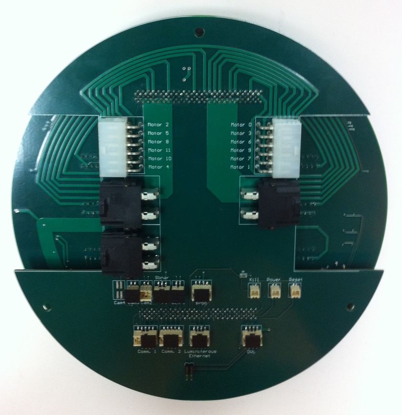
Underwater electrical connections are now              These panels are designed around a
made via neoprene wet-pluggable connectors.         common panel template in SolidWorks
                                                    and can be quickly machined through a
                                                    laser-cutting process and then anodized. The
B. Hull                                             panel redesigns dramatically reduce the design
   The vehicle’s hull is a cast acrylic, 8.5"       and manufacturing time of the Seabee AUV.
inch diameter, cylindrical enclosure spanning
a length of 12 inches. The acrylic is 1/8"          D. Connector Plate
thick, and was selected to reduce unnecessary          The aluminum connector plate supports the
weight and eliminate potential corrosion issues.    hull structurally and allows for water-tight
Its transparency allows visual information from     connectivity between the electrical systems
within the hull to be accessible. It is enclosed    inside the hull and various components
by an aluminum endcap on one side, and an           and enclosures on the vehicle’s frame.
aluminum collar on the other, held together by      All electrical connections are made using
four tension rods. It is kept watertight by the     neoprene wet-pluggable connectors from
use of two gaskets. The hull’s collar attaches to   Teledyne Impulse and Seacon. Additionally,
an aluminum connector plate rigidly mounted         the plate features a valve to pressurize and
to the vehicle frame. The interface between the     depressurize the hull, and ports for the liquid
plate and collar is sealed by the use of two        cooling system.
EPDM O-rings in a bore seal configuration.

                                                          Fig. 3: Battery pod cross-section.
      Fig. 2: Acrylic hull with internals.

                                                E. Liquid Cooling
C. External Frame                                  The SeaBee AUV takes advantage of a
   The external frame consists of an octagonal  unique   liquid-cooling system consisting of
cage surrounding the main hull. Each octagon custom aluminum cooling block, an external
measures 10.836" around an inscribed radiator and a circulation pump to cool the
circle. Panels constructed of T6061 anodized quad-core processor and other highly thermally
aluminum measuring 7" x 4.5" x 3/16" make demanding elements such as H-bridge motor
up the walls of the octagonal cage resulting in drivers. The cooling block is mounted to the
a total of 24 panels. Each panel is associated computer heat-spreader to cool the CPU while
with a certain location of the frame and a simultaneously drawing heat away from the
component. In addition, panels can move H-bridges.
around the frame easily if design changes are
necessary. The front and back surfaces of the F. Flotation System
octagonal cage serve as mounts for the depth       Four 3" diameter, 12" acrylic tubes are
thrusters and the flotation structure.          placed at the four corners of the vehicle to

University of Southern California Autonomous Underwater Vehicle                                  2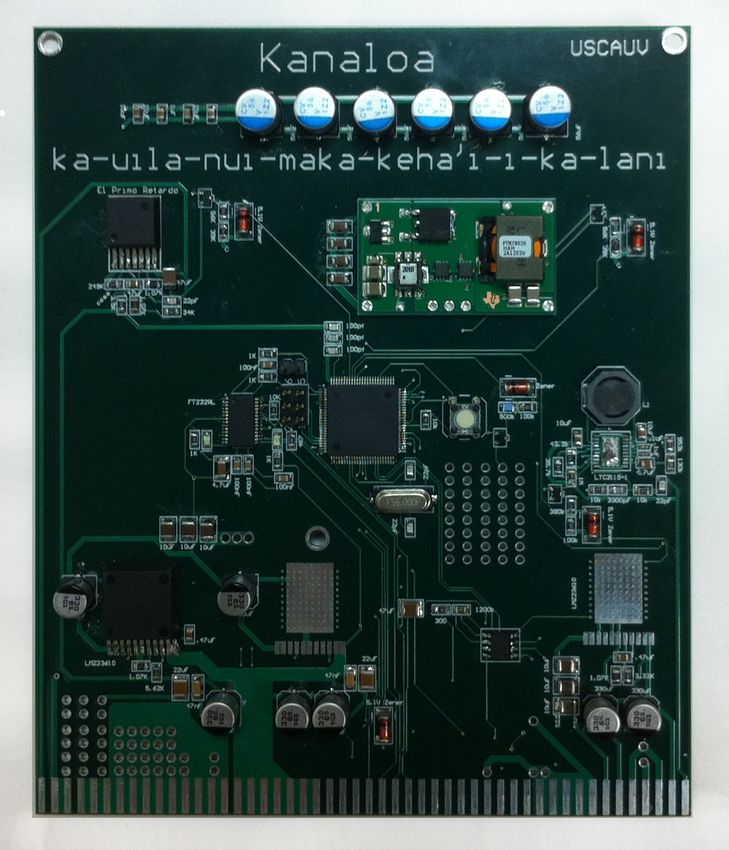
provide flotation. Four adjustable ballast tubes
placed near the flotation tubes make it possible
to dynamically modify vehicle’s buoyancy and
inertial tensor.
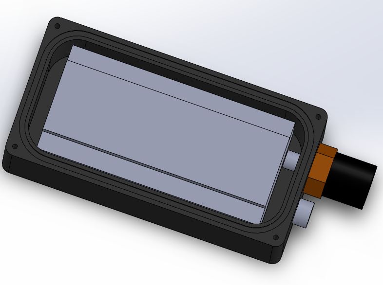
G. Battery Pods
Two aluminum battery enclosures are
mounted to the underside of the vehicle’s
frame. This frees up space for the electrical
systems inside the primary hull. Battery pods
can be hot swapped, allowing for extended
runtime. The battery enclosures feature a
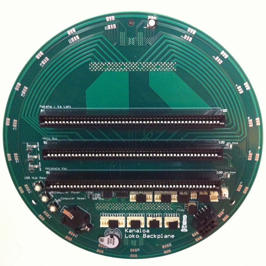
rectangular design in order to compactly fit Fig. 4: Kanaloa primary backplane board.
the rectangular batteries. They are sealed via “Loko”
an O-ring in a face-seal configuration. They
are also fitted with pressure relief valves as
a safety measure to prevent the buildup of
hazardous pressure levels.
H. Auxiliary Enclosures
The vehicle is equipped with four camera
enclosures, a sensor housing, and a sonar case.
All of these enclosures are constructed out of
aluminum, employ wet-pluggable connectors,
and are sealed using O-rings in either a face or
bore seal configuration.
III. E LECTRICAL D ESIGN
Fig. 5: Kanaloa backplane system.
A. Overview
The Seabee electrical system provides the
robot and its systems with power and provides B. Computing
the appropriate interface between all of the To support highly computanionally-intensive
electrical devices. The main electrical system sensing and navigational capabilities, the
is made up of two backplanes, and three Seabee AUV features an ADL Embedded
daughter cards each featuring its own Atmel Solutions ADLQM67PC-2715QE embedded
1280 microprocessor. This eliminates the need computer. The ADL features an Intel i7 Quad
for excessive wires inside the submersible hull, Core in a PCIe/104 form factor. The high
giving the final product a cleaner look, and processor performance makes it ideal for a
increasing the overall reliability by alleviating host of tasks performed by the robot, including
the risk of loose wires and poor connections. sonar localization and image processing. The
The electrical system has been dubbed computer is connected to the rest of the
“Kanaloa”, named after the Hawaiian god often electrical system via a system bus connector,
symbolized by a squid. In honor of the system’s and can connect directly to many of the robot’s
modularity, each of the subsystems housed on input sensors.
their respective daughter cards are named in
honor of some of the various forms Kanloa
would assume in Hawaiian lore. The Kanaloa C. Power
system can be broken into four main parts: Due to the high power consumption of
computing, power, actuation, and sensing. the ADL computer, the Seabee AUV power
University of Southern California Autonomous Underwater Vehicle 3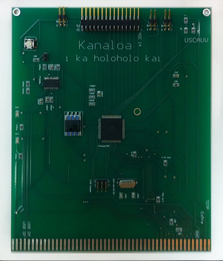
Fig. 6: Power systems overview.
                                                          Fig. 7: Power board. “Kanaloa
                                                         Ka-uila-nui-maka-keha’i-i-ka-lani”
system incorporates multiple hot-swappable
battery packs. The robot is powered by two
25.9 V, 10 amp-hour LiPoly batteries, which
                                                   systems, and voltage monitoring feedback
allow not only the high current draw of the
                                                   systems, allowing the computer to monitor
computer, but provide ample power to each
                                                   current draw and voltage for each supply. The
of the robot’s six thrusters as well. The raw
                                                   daughtercard allows for the shutdown of any
battery lines are connected to the backplane
                                                   individual regulator if overheating occurs, or
affixed to the endcap of the hull, and are
                                                   if the power is not being conditioned within
passed into the power regulating daughtercard
                                                   acceptable bounds.
of the Kanaloa system. This daughtercard
features power switching, forcing the electrical
load of the robot onto the battery with the
                                                   D. Actuation
most charge remaining, ensuring that both
batteries are discharged at the same rate.            Dubbed “Kanaloa-i-ka-holo-nui” after the
Furthermore, this system is diode OR-ed            sub-deity meaning “Kanaloa the swift runner”,
with an external supply, allowing the robot to     the actuation daughtercard features twelve
conserve charge in its batteries while powered     H-bridge motor controllers with PWM. Six
by an external source via a tether. The            controllers directly drive the robot’s thrusters,
power regulation daughtercard is nicknamed         and are able to run them forwards and
“Kanaloa Ka-uila-nui-maka-keha’i-i-ka-lani”,       backwards, as well as to throttle them
after a sub-deity of Kanaloa meaning               effectively via a PWM signal. The other six
“lightening flashing in the heavens”.              controllers can be used for manipulators on
   The daughtercard takes the raw battery          the robot, including the dropper and torpedo
power and conditions it for use by the             firing system. The current draw of each motor
robot’s other systems. The ADL computer            controller is monitored by a current sense
is powered by a 5-volt source and, to meet         resistor, providing the computer with vital
the high current requirements of the ADL           information as to the power being drawn by
(13.4 amps at full load), the daughter card        any motor. The computer is also able to shut
features two LMZ23610 converters, which            off any or all of the motors in the event of a
can be daisy-chained to supply 20 amps.            malfunction. The vehicle employs six SeaBotix
Similar converters supply 3.3V, 12V and 24V        BTD-150 thrusters. They are positioned to
electricity to auxiliary systems. Also featured    allow for control over all six degrees of
on the daughtercard are current monitoring         freedom.

University of Southern California Autonomous Underwater Vehicle                                   4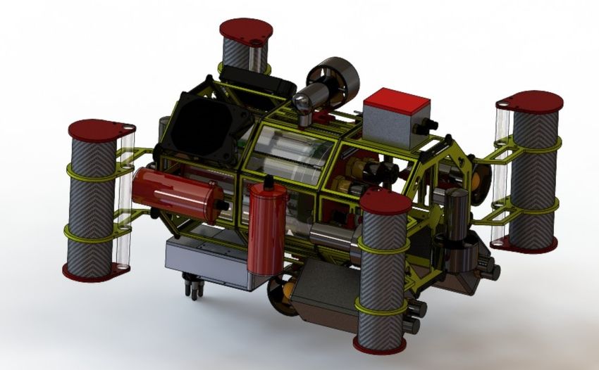
Fig. 8: Tetrahedral sonar array.

                                                               Fig. 9: GPIO Board.
E. Sensing                                                  “Kanaloa-i-ka-holoholo-kai”
   The     robot’s     sensing    system      is
centered around the General Purpose
Input/Output (GPIO) daughtercard nicknamed         downward and two facing forward. This affords
“Kanaloa-i-ka-holoholo-kai”,            meaning    the opportunity for stereo vision in both
“Kanaloa who faces the sea”. The daughtercard      directions, allowing for estimations of depth,
processes the input from sensors and               as well as optical flow tracking on the
communicates with the ADL computer                 bottom of the pool for estimations of position.
over USB. Locally, the daughtercard houses         The robot’s Hyrdophone Array Sensor (HAS),
the robot’s internal pressure sensor, which        features a tetrahedral array of RESON TC4013
provides the ADL with information as to            Hydrophones. The sonar signals are processed
whether or not the pressurized hull is leaking.    by a Danville Signal dspstak DSP engine, and
Connected to the GPIO card via the backplane       are sent to the computer to provide direction
are various other internal sensors, including      and distance to the target ping.
the robot’s temperature thermistor, a flowmeter
sensor from the robot’s liquid cooling system,
and an RPM sensor from the liquid cooling
pump, allowing the ADL to monitor these
systems effectively. The robots Remote
Input/Output (RIO) systems are located in the
robot’s RIOpod. The RIOpod communicates
with the main daughtercard over SPI, and
houses the external pressure sensor, external
temperature sensor, and Xsens MTi Attitude
Heading Reference System (AHRS). The data
from the pressure sensor is sampled remotely
by an ADC in the RIOpod.
   Other RIO systems on the robot do not
go through the daughter board, but are
attached directly to the ADL for convenience.      Fig. 10: Kanaloa secondary backplane board.
Among these are the robot’s four Point                               “Waho”
Grey Firefly FMVU-03MTC cameras. These
cameras are grouped in pairs, two facing

University of Southern California Autonomous Underwater Vehicle                                 5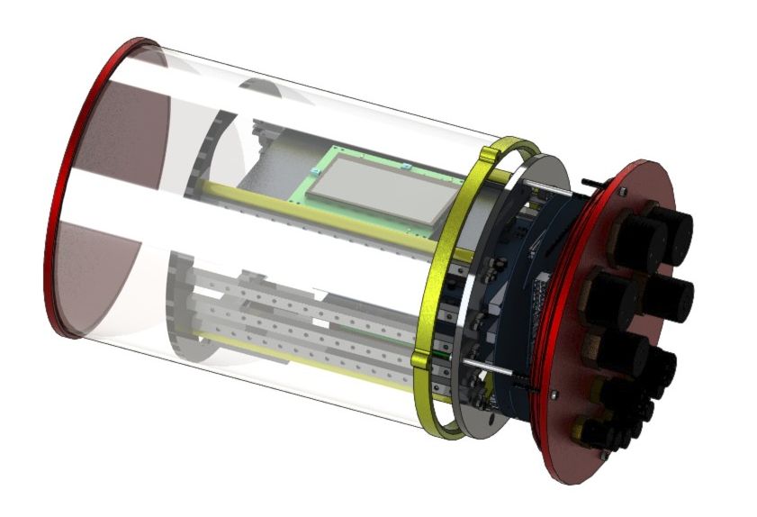
F. Killswitch
   The killswitch was designed with reliability
as the primary focus. The design is robust
and minimal while remaining functional in
demanding situations. A single reed switch is
mounted inside the primary hull, actuated by
a magnet tethered to the outer hull. A tiny
logic-gate-based circuit ascertains the state of
the reed switch and produces a 5V TTY “kill”
signal to the microcontroller on the power            Fig. 11: Computing and communications
board. The microcontroller is then responsible                   systems overview.
for placing the motor and actuator drivers into
a low-power state. If the robot enters the “kill
state”, action can be halted until the state is        2) ROS: USC AUV has used ROS, an
exited and then proceed as normal, allow for       open-source toolkit developed by Willow
safe testing.                                      Garage, since the 2010 RoboSub competition.
                                                   ROS, or the “Robot Operating System”,
                                                   provides a language-generic, modular paradigm
           IV. S OFTWARE D ESIGN
                                                   for the development of software systems along
A. Overview                                        with fairly generic implementations of many
                                                   common algorithms known to the field of
   The physical capabilities of the SeaBee
                                                   robotics, including such categories as sensing,
AUV are constantly changing in terms of both
                                                   navigation, planning, and visualization.
mechanical and electrical systems. This has
                                                       3) uscauv-ros-pkg: While ROS provides
necessitated the design of a robust, dynamic
                                                   a solid foundation on which to build,
software architecture specifically engineered
                                                   working within the toolkit often involves
to maximize both functionality and ease of
                                                   creating        unnecessary        redundancies
implementation through the use of a modular
                                                   across implementations. Furthermore, the
paradigm. Similar modules are connected via
                                                   serialization-free communication described
generic interfaces, allowing for high levels
                                                   above is traditionally time consuming to set
of specificity where necessary while still
                                                   up, as modules utilizing it must follow the
ensuring the trivial addition and removal of
                                                   “nodelet” paradigm rather than the more
modules as physical constraints vary, even
                                                   common “node” paradigm. The open source
at runtime. Furthermore, several pipelines,
                                                   (BSD License) uscauv-ros-pkg software
including vision, localization, and navigation,
                                                   package provides generic wrapper classes and
have been implemented to handle the complex
                                                   scripts designed to speed up ROS development,
process of feature conversion and filtering,
                                                   as well as modular implementations of
starting with low-level, often noisy feature
                                                   common robotics algorithms such as Kalman
sources such as physical sensors, and ending
                                                   filters and template-based pattern matching.
at the high-level representations required for
efficient planning and decision making.
                                                   C. Sensing
                                                      Currently, the most advanced sensor on
B. Architectures                                   the SeaBee AUV is the XSens MTi AHRS.
   1) Ubuntu: The Seabee AUV primary               The AHRS utilizes onboard rate gyroscopes,
computer runs Ubuntu Linux 12.04 “Precise          accelerometers, and magnetometers with an
Pangolin” as its operating system. This            Extended Kalman Filter to produce a stable
selection was made based on the open-source        estimate of orientation in real time at 100 Hz.
nature of Ubuntu, its portability, and its good       The robot’s hull is also fitted with an external
support for the intended software architecture.    pressure sensor, which is used to estimate the

University of Southern California Autonomous Underwater Vehicle                                     6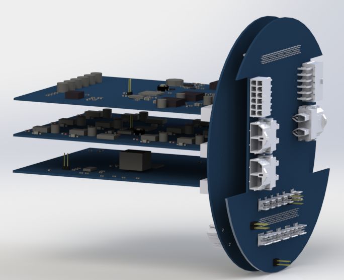
OpenCV functions to de-bayer and un-distort
                                                    (given a camera calibration) the incoming
                                                    raw images. A modular “image scaler” node
                                                    allows for images to be easily converted
                                                    across scale space before being fed into
                                                    different image processing algorithms. This
                                                    approachs conserves bandwidth by ensuring
                                                    that high-resolution images are only utilized
                                                    when this level of detail is required for optimal
                                                    algorithm performance.

                                                    E. Landmarks
       Fig. 12: Software configuration.
                                                       The Seabee AUV navigation approach is
                                                    centered around landmark-oriented visual
absolute depth of the AUV below the surface         odometry. Recognition and subsequent
of the water via an experimentally-derived          localization relative to landmarks, or unique
conversion from arbitrary pressure units to a       competition objects, is critical to success in
distance in meters. With the current electronics    the RoboSub competition when the robotic
infrastructure, this measurement is taken at 10     platform used is not aided by a Doppler
Hz.                                                 Velocity Log; however, these landmarks
   Without a Doppler Velocity Log (DVL), we         are subject to change each year. The robot
must rely on alternate, often noisy sources         utilizes an extensible landmark recognizer
of odometry. We have found it necessary to          that accepts a landmark filter and calls
develop both a generic realtime simulation          on child modules to perform specialized
of our vehicle’s dynamics, as well as a             landmark recognition. This ensures that,
generic Bayesian measurement fusion system          with the exception of drastic changes
capable of combining all components of all          to the competition, landmark-dependent
observables, whether simulated or physical,         algorithms can remain mostly unchanged,
into corresponding “filtered” measurements.         while specialized recognition algorithms can
                                                    be easily developed, tested, and deployed
                                                    through a standard, familiar interface. We
D. Vision Pipeline                                  assume that certain landmarks are only located
   The Seabee AUV views the world through           within certain parts of the competition pool,
four PointGrey Firefly USB cameras: two             and we further assume that given an arbitrary
facing forward and two facing downward. Both        set of goals, only some subset of these
cameras are configured to stream Bayered            landmarks need to be recognized. Given these
640x480 images at 60 hz. While the hardware         assumptions, we conclude that it is possible
interface to these cameras is USB, they             to search for only some subset of landmarks
support the IIDC 1394-based Digital Camera          dependent on the current location and/or
Specification over USB, allowing for the use        goal. Therefore, it is desirable to utilize some
of “firewire” camera drivers.                       simple means of applying a landmark filter,
   Images streamed from the cameras are             with either narrowing or widening constraints,
bayered and distorted by various optical effects,   through recognition algorithms, in order to
including those from the camera lenses and          improve performance. We accomplish this
the results of different physical mediums           via a custom color- and shape-based filtering
surrounding the sensor tubes containing the         API that accepts a list of filter items, each
cameras. To compensate for these effects, we        specifying either a narrowing or widening
use a community-developed ROS node called           constraint to be applied to the color or type
“image proc”, which utilizes several common         of a landmark. For example, when we are

University of Southern California Autonomous Underwater Vehicle                                    7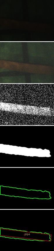
attempting to locate a buoy, we look for
orange pipelines and buoys of any color on
approach, then look for buoys of a single color
on each buoy-touching attempt, then look for
only orange pipelines and yellow hedges as
we attempt to locate the first hedge, etc.

F. Color Classifier
   Image segmentation is achieved using a a
trained Support Vector Machine encapsulated
in a “color classifier” node. This approach
was selected to facilitate robust color detection
despite inconsistent lighting and water
visibility. The SVM performs well for this task,
as it is able to incorporate highly-nonlinear
decision boundaries, which is key in poor
lighting conditions where the perceptual
distance between target colors and the water
is very low. The color classifier node accepts
a stream of color images and produces binary
masks in which positively-classified pixels
correspond to a specific color on which
the SVM was trained. Training the color
classifier involves producing “training images”
- masks in which the user has positively
identified the target colors. Multiple training
images are simulataneously fed into a custom
classifier program. The SVM is trained using
radial basis functions (RBFs), and the SVM
hyperparameter C is optimized using a grid
search. The color classifier program produces
a YAML description of the color. Multiple
YAML color descriptions are dynamically
loaded by the color classifier node at runtime.
Classification is parallelized, with one thread
allocated for each color. The output images are
bit-shifted and OR-ed to produce an efficient
color representation that can be quickly
transported to sucessive nodes.

G. Shape Detector
  Landmark detection is achieved using a
“shape detector” node. This node matches 2D
shapes from binary color classifier images
to pre-loaded templates to produce a set of
                                                    Fig. 13: The stages of the vision pipeline as it
candidate landmark locations. The first stage
                                                               detects a path segment.
of the shape-detector algorithm is finding
contours in the color classifier data. This is
achieved using the OpenCV implementation

University of Southern California Autonomous Underwater Vehicle                                   8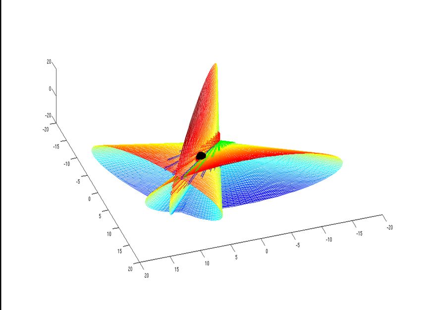
of the algorithm proposed by Suzuki et al.
For each contour, we compute a “radial
histogram”, where bins are indexed by radial
distance from the contour’s centroid. Radial
histograms are normalized for scale and
rotation. These histograms are compared with
template histograms for objects such as buoys
and pipes using the Earth Mover’s Distance.
This approach is robust to partial occlusion and
can be easily tuned.

H. Object Tracker

   The Seabee AUV software architecture
incorporates Kalman filters to obtain improved       Fig. 14: Object tracker output visualized in
estimates for landmarks. Following shape            RVIZ tool. The strongest hypothesis is tied to
detection, candidate shape locations are                     the 3D path segment model.
converted from image coordinates to world
coordinates. This is achieved by reprojecting
the image coordinates to 3D using known             I. Sonar
camera intrinsics. Each object is defined in
a tree data structure in which each node               Computation is distributed between the
contains shape and color information. This          vehicle’s primary computer, located in the
hierarchy of colored shapes is flexible enough      main hull, and the dspStak processor, located
to support all of the visual landmarks found        inside the sonar pressure vessel. The dspStak
at RoboSub. Object descriptions are stored          preprocesses incoming signals by applying a
in a compact YAML format. Each object is            gaussian filter and threshold. It then performs
initially alloted a single Kalman filter. The       the fast fourier transform (FFT) on each
Kalman filters use an eight-dimensional state       signal and, for each hydrophone signal pair,
space which describes the object’s X/Y/Z            computes the phase difference between the
position, rotation parallel to the camera plane,    fundamental frequencies. RANSAC is applied
and a corresponding velocity for each of these      to this vector of phase difference estimates to
parameters. This system is augmented by using       produce a global phase difference estimate that
multiple Kalman filters to represent multiple       is robust to non-common-mode noise. These
hypotheses as to the location of each object.       phase differences are then sent to the primary
When the system receives a new measurement          computer via an RS232-over-USB interface.
input, it computes the conditional probability      This approach minimizes the bandwidth of
of the measurement for each filter with a           the data transfer between the dspStak and the
matching shape and color. The measurement           computer. Using an IEEE 754 double-precision
is incorporated by the filter with the highest      floating point representation the worst-case
conditional probability. If the probability falls   bandwidth, assuming a 192 kHz sampling rate
below an empirically-determined threshold           and a rolling window on the input signal, is
for all of the existing filters, a new filter is    6.2 MB/s. To compute pinger location from
spawned. Filters are deleted if their variance      phase differences, a convex-optimization-based
becomes too large. For each object, the             approach was applied. It is known that each
estimate from the filter with the highest           phase difference describes the surface of
confidence is continuously published to other       a cone on which the pinger must lie in
nodes.                                              order to have produced the measured phase

University of Southern California Autonomous Underwater Vehicle                                  9
difference. The exact location of the pinger                          to produce mass, volume, mass centroid,
is determined by intersecting these cones.                            volume centroid, and inertial tensor estimates
However, susceptibility to measurement                                for the robot body. The current simulator
noise means that a precise intersection of                            implements buoyant forces, gravitational
all four phase cones is unlikely to exist.                            forces, and thruster forces. For the simulator to
Mathematical optimization is applied as a                             become a viable tool for robot state estimation,
solution to this problem. For each cone, a                            an estimate of drag forces on the AUV body
point on the surface can be described by                              must be implemented. As fluid dynamics
two parameters: A distance l along the axis                           are highly nonlinear and nondeterministic,
from which the cone opens and an angle θ                              producing an accurate real-time model is a
around this axis. With four cones, we have                            subject interest for continued research. As it
eight parameters l1 , l2 , l3 , l4 , θ1 , θ2 , θ3 , θ4 . The          stands now, the physics simulator is a useful
problem of intersecting the cones can then be                         tool for verifying control system inputs.
posed as follows:
                                                                                    V. F UTURE W ORK
                                           4
                                           �
                     min                          In the coming year USC AUV will enter
                                               fn (ln , θn )2   (1)
          l1 ,l2 ,l3 ,l4 ,θ1 ,θ2 ,θ3 ,θ4
                       n=1                     the  second half of the SeaBee design cycle.
                                               Main features for the new design will include
  Where fn (l, θ) is the function describing
                                               a new hull and increased actuator capability.
the position of a point lying on cone
                                               USC AUV will hold both a Preliminary
n. Optimization was implented using the
                                               Design Review (PDR) and Critical Design
GNU Scientific Library Multidimensional
                                               Review (CDR) to obtain feedback from
Minimization toolkit.
                                               research and industry experts. In addition,
                                               USC AUV will increase its outreach into
                                               the community by repeating involvement in
                                               the USC Beyond the Bell program, USC
                                               Robotics Open House, and the USC Viterbi
                                               School of Engineering Open House while
                                               also increasing participation to include USC’s
                                               Engineering Week, partnership with other USC
                                               Organizations for outreach into elementary and
                                               middle school STEM education, and a formal
                                               program with high school after-school math
                                               and science programs. For more information,
                                               please visit http://uscauv.com
Fig. 15: Sonar phase cones intersecting at the
                   pinger.                                   ACKNOWLEDGMENT
                                                                         Support from The University of Southern
                                                                      California, iLab, the USC Dornsife College
J. Physics Simulation                                                 of Letters, Arts, and Sciences Machine Shop,
   To produce the necessary simulation                                and the Viterbi School of Engineering allows
parameters for the Seabee AUV, the Solidworks                         USC AUV to continue to be an integral part of
CAD program was utilized. Material properties                         student research at the USC Viterbi School of
for the entire AUV were modeled. Once                                 Engineering.
individual component models were produced,                               Thank you to our industry sponsors:
they were assembled into a global robot                               the Boeing Company, Northrop Grumman,
model. The mass properties and locations of                           Digi-Key Corporation, Lockheed Martin, and
the components in this model were aggregated                          ADL Embedded Solutions.

University of Southern California Autonomous Underwater Vehicle                                                     10
R EFERENCES
[1] Emery, William J., Thomson, Richard E., Data analysis
methods in physical oceanography, Gulf Professional
Publishing. p. 83, 2001.
[2] Julier, S.J.; Uhlmann, J.K, A new extension of the Kalman
filter to nonlinear systems, Int. Symp. Aerospace/Defense
Sensing, Simul. and Controls 3 , 1997.
[3] Thrun, Sebastian, Montemerlo, Michael, Koller, Daphne,
Wegbreit, Ben, FastSLAM 2.0: An Improved Particle
Filtering Algorithm for Simultaneous Localization and
Mapping that Provably Converges, IJCAI 2003
Workshop on Empirical Methods in Artificial Intelligence,
2003.
[4] Suzuki, S. and Abe, K., Topological Structural Analysis
of Digitized Binary Images by Border Following. CVGIP
30 1, pp 32-46 (1985)
[5] J. Shi and C. Tomasi. Good Features to Track. Proceedings
of the IEEE Conference on Computer Vision and Pattern
Recognition, pages 593-600, June 1994.
[6] Rubner. C. Tomasi, L.J. Guibas. The Earth Movers
Distance as a Metric for Image Retrieval. Technical Report
STAN-CS-TN-98-86, Department of Computer Science,
Stanford University, September 1998.
University of Southern California Autonomous Underwater Vehicle 11You can also read