Verification, Validation and Certification of Embedded Software
←
→
Page content transcription
If your browser does not render page correctly, please read the page content below

Verification, Validation and Certification of
                    Embedded Software

                                      Presented by:
                                    Akramul Azim, PhD
Assistant Professor – Software Engineering and Head of Real-Time Embedded Software (RTEMSOT) Lab
                              Faculty of Engineering and Applied Science
                                        Ontario Tech University
Embedded Software Systems
• Systems that are designed for a specific purpose.

 1/28/2020                                            2

Embedded Software Systems – Some Market
                Drivers
• Autonomous vehicles
• Multimedia products and portables
• Healthcare
• Machine-to-machine (M2M) communication
• Manufacturing automation
• Home automation
• Internet of things

 1/28/2020                                 3
Systems Getting Complex and More Connected

• Increasing processors (e.g., 100+ processors in modern cars).
• Increasing number of sensors, controllers
• Big data gathering and processing
• Real-time integration/connection of embedded systems

 1/28/2020                                                        4

Embedded Software Complexity
• Software that executes in an safety-critical software system.

               Source: National Instruments white paper, published on December 2015

 1/28/2020                                                                            5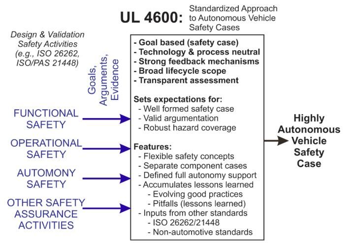
Embedded Software Growth
• F-22 Raptor (1997): 1.7M lines of code
• F-35 Joint Strike Fighter (2006): 5.7M lines of code
• Boeing 787 (200x): 6.5M lines of code

- Mariner (1962): 20 lines of code
- Voyager (1977): 3000 lines of code
- Mars exploration rover (2003): 4M lines of code

1/28/2020                                                6
Properties of Embedded Software
• Resource constrained: For example, 32kb of program
    memory, 1kb of RAM
• Low power: device should last for long time
• Production cost sensitive: recurring production costs
    matter more than non-recurring engineering costs.

1/28/2020                                                 7
Is Designing Embedded Software System Easy?

 1/28/2020                               8

Example: Mars Pathfinder (1997)

1/28/2020                                     9

Facts: Mars Pathfinder (1997)
• Pathfinder started resetting after operating for few days
• Problem: priority inversion problem
• Fix: traces from ground model, online software update

1/28/2020                                                     10
Oerlikon GDF-005

1/28/2020                      11
Oerlikon GDF-005
• Semi and full-automatic ground to air defence system
• Problem: failure to detect faults
• Consequence: 9 soldiers killed, 14 injured
• Fix: none

1/28/2020                                                12
Example: Therac 25

1/28/2020                        13
Facts: Therac 25
• Therac 25 was a radio therapy machine by AECL caused
       - excessive radiation
       - 6 accidents which led to deaths or serious injuries
• Problem: race conditions, overflow, missing safety interlocks
• Fix: software updates

1/28/2020                                                         14
Some Recent Embedded Software Failures
• Software caused three engines on a Spanish Airbus
A400M Atlas military transport plane to improperly shut
down during a flight in May 2015, causing it to crash and
killing four crew members
• In July 2015, two researchers demonstrated how to take
over a Jeep Cherokee using the car’s telematics system,
shutting off the engine and disabling the brakes while a
journalist drove the car
Source https://www.computer.org/csdl/mags/co/2016/01/mco2016010088.pdf
1/28/2020 15The Financial Fallout
https://www.bloomberg.com/news/articles/2019-07-27/latest-737-max-fault-that-alarmed-test-pilots-rooted-in-software
1/28/2020 16The Cost of Errors
20.5% 30x
Requirements Acceptance
Engineering Test
0%, 9% 15x
System System
Design 70%, 3.5% 10%, 50.5% Test
1x 10x
Software
Integration
Architectural
Test
Design
20%, 16%
Component
Unit
Software 5x Test
Design
Source: NIST Planning report 02-3,
The estimated nominal cost for fault removal
“The Economic Impacts of Inadequate Where faults are introduced
Infrastructure for Software Testing”,
May 2002. Where faults are found
Code
DevelopmentVerification & Validation (V&V) • Verification: ensuring that a subsystem (or step in the design) meets the objectives for that subsystem, i.e., it does what we want it to do. • Validation: ensuring that the whole system meets the requirements, i.e., it does what it is supposed to do.
Certification
• Certification: convincing a given authority that the validation process is
   correct.
• Certification is typically process-based.
• Establish good process management practices to track requirements, as well
   as quality and conformance of the deliverables.
• Certification is typically very expensive!
    –    Document everything
    –    Review everything (use different people – independent
         verification/validation)
Validation, Verification, and Certification
ChallengesCommon Challenges
Interoperability
– Currently equipment of vendor X only works with other equipment of
vendor X
– Strong push for an open medical interoperability standard
– Problem #1: if something goes wrong, who gets the blame?
– Problem #2: equipment vendors have nothing to gain.
Wireless Communication
– Solve the cable mess
– Problem: how to resist interference and jamming?
– Some physical-layer techniques are promising (Ultra-Wide Bandwidth,
Dynamic Frequency Selection…)Quick Check
#include
int main()
{
float x;
float xPlus1;
float xPlus2;
float xPlus3;
float xPlus4;
x = 16777216.0;
xPlus1 = x + 1.0;
xPlus2 = x + 2.0;
xPlus3 = x + 3.0;
xPlus4 = x + 4.0;
printf("x is %f\n", x);
printf("x+1 is %f\n", xPlus1);
printf("x+2 is %f\n", xPlus2);
printf("x+3 is %f\n", xPlus3);
printf("x+4 is %f\n", xPlus4);
return 0;
}Answers • x is 16777216.000000 x+1 is 16777216.000000 x+2 is 16777218.000000 x+3 is 16777220.000000 x+4 is 16777220.000000
Certification Standards
Organizations
• International Organization for Standardization (ISO),
  Founded in London in 1946
• International Electrotechnical Commission (IEC), Founded
  in 1906
• Both are based in Geneva
• Each country gets one vote
Standards
• ISO 14971 : Medical devices
• ISO 25119: Tractors and machinery for agriculture and forestry –
  safety-related parts
• ISO 26262: Road vehicles – functional safety
• IEC 61508: Functional safety of electrical/electronic/programmable
  electronic safety-related systems
• IEC 61513: Nuclear power plants – Instrumentation and Control
  Important to Safety – General requirements for systems
• IEC 62138: Nuclear power plants – Instrumentation and Control
  Important to Safety – Software aspects
• IEC 62304: Medical device software
Safety Integrity Level (SIL)
Probability of Failures
• What does the failure per hour is less than 10-8 mean?
   - 108 hours is 11408 years
   - Moreover, to make a statistical argument, sufficient
    samples are required
   - Perhaps, 95 to 105 failures in 1010 hours
   - Is it possible to claim?
Understanding SILs • SIL 1 - represents the integrity required to avoid relatively minor incidents and is likely to be satisfied by a certain degree of fault tolerant design using guidelines that follow good practice. • SIL 2 - represents the integrity to avoid more serious, but limited, incidents some of which may result in serious injury or death to one or more persons. • SIL 3 - represents the integrity required to avoid serious incidents involving a number of fatalities and/or serious injuries. • SIL 4 - represents the integrity level required to avoid disastrous accidents.
Assignment of SILs according to
       Controllability
Compliance with SILs
• SIL levels for field instruments are established by one of two
methods:
- FMEDA (Failures Modes, Effects and Diagnostic Analysis) is best
when reviewed or certified by a third party. A systematic analysis
technique is necessary to determine failure rates, failure modes and
the diagnostic capability as defined by standards.
- Proven In Use (also called Prior Use) is typically used by a
customer with a mature instrument in known processes. This
approach requires sufficient product operational hours, revision
history, fault reporting systems and field failure data to determine if
there is evidence of systematic design faults in a product.IEC 61508
• This International Standard
– by International Electrotechnical Commission
– considers all relevant overall, E/E/PE system and software
safety lifecycle phases (for example, from initial concept,
through design, implementation, operation and maintenance to
decommissioning) when E/E/PE systems are used to perform
safety functions.The Parts of IEC 61508
• IEC 61508-1 Part 1: General requirements
• IEC 61508-2 Part 2: Requirements for electrical/electronic/programmable electronic
safety-related systems
• IEC 61508-3 Part 3: Software requirements
• IEC 61508-4 Part 4: Definitions and abbreviations
• IEC 61508-5 Part 5: Examples of methods for the determination of safety integrity
levels
• IEC 61508-6 Part 6: Guidelines on the application of IEC 61508-2 and IEC 61508-3
• IEC 61508-7 Part 7: Overview of techniques and measuresIEC 61508: Guide to the Selection of
TechniquesIEC 61508: Selection of Techniques
IEC 61508: Selection of Techniques
ISO 25119
• Standard for tractors and machinery for agriculture and
  forestry
 - ISO 25119-1: Part 1: General principles for design and
  development
 - ISO 25119-2: Part 2: concept phase
 - ISO 25119-2: Part 3: Series development, hardware and
  software
 - ISO 25119-4: Part 4: Production, operation, modification and
  supporting processes
ISO 26262
• ISO 26262 consists of the following parts, under the general title Road
  vehicles — Functional safety:
  - Part 1: Vocabulary
  - Part 2: Management of functional safety
  - Part 3: Concept phase
  - Part 4: Product development at the system level
  - Part 5: Product development at the hardware level
  - Part 6: Product development at the software level
  - Part 7: Production and operation
  - Part 8: Supporting processes
  - Part 9: Automotive Safety Integrity Level (ASIL)-oriented and safety-
   oriented analyses
  - Part 10: Guideline on ISO 26262
Safety Levels
• Automotive SIL A (ASIL A)
• Automotive SIL B (ASIL B)
• Automotive SIL C (ASIL C)
• Automotive SIL D (ASIL D)
Some testing recommendations from
            ISO 26262
Hardware-software integration and testing • Requirements based test • Fault injection test • Back to back test • Performance test • Interfaces testing • Error guessing test • Resource usage test • Stress test
Hardware-software integration and testing

• Requirements-based test: A requirements-based test denotes
  a test against functional and non-functional requirements
• Fault injection test: A fault injection test uses special means
  to introduce faults into the test object during runtime. This
  can be done within the software via a special test interface or
  specially prepared hardware. The method is often used to
  improve the test coverage of the safety requirements,
  because during normal operation safety mechanisms are not
  invoked.
Hardware-software integration and testing

• Back-to-back test: A back-to-back test compares the
  responses of the test object with the responses of a
  simulation model to the same stimuli, to detect
  differences between the behaviour of the model and its
  implementation.
• Performance test: A performance test can verify the
  performance (e.g. task scheduling, timing, power output)
  in the context of the whole test object, and can verify the
  ability of the intended control software to run with the
  hardware.
Hardware-software integration and testing
• Interface testing: Interface tests of the test object
  include tests of analogue and digital inputs and outputs,
  boundary tests and equivalence-class tests to completely
  test the specified interfaces, compatibility, timings and
  other specified ratings for the test object. Internal
  interfaces of an ECU can be tested by static tests for the
  compatibility of software and hardware as well as
  dynamic tests of Serial Peripheral Interface- (SPI) or
  Integrated Circuit- (IC) communications or any other
  interface between elements of an ECU.
Hardware-software integration and testing
• Error guessing testing: An error guessing test uses expert
  knowledge and data collected through lessons learned to
  anticipate errors in the test object. Then a set of tests
  along with adequate test facilities is designed to check
  for these errors. Error guessing is an effective method
  given a tester who has previous experience with similar
  test objects.
Hardware-software integration and testing
• Resource usage test: A resource usage test can be done
  statically (e.g. by checking for code sizes or analyzing the code
  regarding interrupt usage, in order to verify that worst-case
  scenarios do not run out of resources), or dynamically by
  runtime monitoring.
• Stress test: A stress test verifies the test object for correct
  operation under high operational loads or high demands from
  the environment. Therefore, tests under high loads on the
  test object, or with exceptional interface loads, or values (bus
  loads, electrical shocks, etc.), as well as tests with extreme
  temperatures, humidity or mechanical shocks, can be applied.
Hazard and Risk Analysis
• Hazards are effectively passive situations that may give
  rise to risks.

• The analysis of risk by defining the intended use of the
  device, identifying the potential hazards and identifying
  the risk associated with each hazard.

• Hazard and Risk Analysis are performed by building
  assurance/safety cases
Fault Trees
• Fault tree analysis (FTA) is a top down, deductive failure analysis in
  which an undesired state of a system is analyzed using Boolean
  logic to combine a series of lower-level events.
• Applying
    - Postulate top event (fault)
     - Branch down listing faults in the system that must occur for the
   top event to occur
    - Consider sequential and parallel or combinations of faults
    - Use Boolean algebra to quantify fault tree with event
   probabilities
   - Determine probability of top event
Bayesian Belief Nets (BBNs)
• Powerful graphical framework in which to reason about
uncertainty using diverse forms of evidence
• Nodes of graph represent uncertain variables
• Arcs of graph represent causal or influential relationships
between the variables
• Associated with each node is a probability table (NPT)
A P(A |B,C)
P(B | C) B
C P(C)
D P(D)Defects BBN (simplified)
Problem Complexity Defects Introduced Design Effort
Testing Effort Defects Detected Residual Defects
Operational usage Operational defectsISO 62304 (Medical) case study: A Patient Monitoring System (PMU)
Hazard and Risk Analysis
• Hazard: Power Supplies.
• Associated Risk: The external power supply might fail, switching the
   PMU to operating on batteries and the care provider not be aware
   that monitoring will only continue for a limited time.
• Mitigation: If external power fails when the PMU is monitoring a
   patient then the relay is closed to alert a human.
• Residual Risk: The battery might not be sufficiently charged to
   allow the PMU to react correctly to the external power failure.
PMU - Failure Analysis
• Build fault trees incorporating the identified risks to
  cover:
     - the probability of the PMU failing to meet its
  Functional Safety Requirements.
    - the probability of the PMU failing in a dangerous
  manner.
• Use expert opinion to identify the risks associated with
  each hazard.
PMU – Failure Analysis
• Components failure analysis
- Assume operating system is a SIL3 system. So, the
failure probability of failure in 24 hours
PFO < 2.4 × 10⁻⁶
- Assume hardware is SIL1. the failure probability of
failure in 24 hours
PFH < 2.4 × 10⁻⁶What’s upcoming and the future?
UL 4600: “Standard for Safety for the Evaluation
          of Autonomous Products”
  • Current safety standards provide essential guidance for
      designing safe vehicles.
  • However, existing standards such as ISO 26262 and ISO/PAS
      21448 were envisioned for vehicles that ultimately have a
      human driver responsible for safe operation of the vehicle.
  • Rather than require a particular technical approach, UL 4600
      concentrates on ensuring that a valid safety case is created. A
      safety case includes three elements: goals, argumentation, and
      evidence.

  1/28/2020                                                         56
Overview of UL 4600
Source: https://medium.com/@pr_97195/an-overview-of-draft-ul-4600-
standard-for-safety-for-the-evaluation-of-autonomous-products-a50083762591
1/28/2020 57Advantages of UL 4600
• UL 4600 provides a uniform set of rules
• UL 4600 is specifically designed from the ground up for highly
autonomous vehicles
• UL 4600 is designed to evolve quickly (for a standard) over
time.
• UL 4600 uses feedback loops to permit managing the risk of
“unknowns.”
1/28/2020 58Why Testing is Essential in UL 4600?
• For each of the safety case developed in UL 4600, it is required
to provide evidence.
• Testing enables evidence to the safety cases.
• The details of the testing requirements can be found in the
draft UL 4600 (pages 200-220). The draft can be found at:
https://edge-case-research.com/ul4600/
(Published December 13, 2019)
1/28/2020 59Mandatory Verification Items in UL 4600 a) Identify V&V methods and extent used b) V&V Coverage c) Testing d) Run-Time Monitoring (New*) e) Safety Case Updates (New*) 1/28/2020 60
Thank You. Any Questions?

                              Contact:
                         Akramul Azim, PhD
            Assistant Professor in Software Engineering
Head of Real-time Embedded Software Lab, Ontario Tech University
               Email: akramul.azim@ontariotechu.ca
            Research Lab Website: www.rtemsoft.com
You can also read