Volume 10, Issue 2, February 2021 - IJIRSET
←
→
Page content transcription
If your browser does not render page correctly, please read the page content below

Volume 10, Issue 2, February 2021
International Journal of Innovative Research in Science, Engineering and Technology (IJIRSET)

                           | e-ISSN: 2319-8753, p-ISSN: 2320-6710| www.ijirset.com | Impact Factor: 7.512|

                                       || Volume 10, Issue 2, February 2021 ||

                                       DOI:10.15680/IJIRSET.2021.1002068

Design and Fabrication of Programmed Grass
                 Trimmer
           Joel Emmanuel D1 , Vishal K2* , Swetha K 3 , Aravind S1 , Deepa R1 , Sarmila Devi R1
                                  HCL TECH BEE Scholars HCL Technologies , India1
                           Research Scholar, SSN College of Engineering, Kalavakkam, India 2
                                      PROGRAM ANALYST COGNIZANT, India 3

ABSTRACT: A Programmed Grass Trimmer is developed like a robotic lawn mower with low cost. The trimmer has a
different type of b lade other than Reel (spiral) or rotary blade. It has the ability to cut the grass at a certain height. The
trimmer has a control unit connected to the I/O device to control. The signal fro m the I/O device is sent to the control
unit. The control unit modifies the signal give it to the co rresponding systems. The trimmer has a suction unit to collect
the grass. The main purposes of our trimmer are to use the trimmed grass as a cattle feed for domestic an imals. The
trimmer has a comb attachment to plough and lifts the grass. The trimmer is e lectrically controlled. The trimmer has a
sensing unit to sense the obstacles around the trimmer which may damage the blade.

KEYWORDS: Grass trimmer, I/O device, Suction unit, Suction unit, Cattle feed.

                                                      I. INTRO DUCTIO N

In the European country, King Budding aimed to cut a lawn on sports grounds and gardens and to play a v irtual role in
the planning of modern sporting ovals, etc.This introduction to the case of the many games, as well as basketball, court
game, etc., to the garden tool diode. Ten more years back, Tho mas Inexperienced introduced a lawn instrument called a
silent cutter that used a sequence drive to transmit electricity, so field mowers became an addit ional cost -effective
variety for do mesticating grazing animals.Today, everything is machine -controlled, and the modern technology is like
the mission of each maker to invent a co mmodity and make it all easier for hu mans. With the rapid advancement of
technology, we begin to see that more people are making widespread use of it, contributing to electricity scarcity and
shortages and therefore substantial emissions. Therefore, in recent years, many testing methods produced for the
navigation and construction of vehicles have been measured squarely. The biggest difference we have managed to
make in our system is that the use of Arduino Uno, which also serves as the heart of the grass cutter using motor drives,
makes the grass cutter quick to navigate the corresponding stop until it meets an obstacle with the aid of unhearable
sensors.The grass cutter and the square calculation of the engines are attached to a microcontroller that governs the
operation of all the engines. In addition to the problem of safety of the assembly as human safety, the identification of
obstacles may be a critical concern for the small controller to be interfaced with a sensing element unit that performs
object detection. A pre-programmed action is taken by the controller to detect the target or obstacle in co mpliance with
the conditions perceived by the sensing element. The main purpose of programmed grass trimmer is to avoid fuel
consumption and reduce the human effo rt, operating cost, and maintenance cost. Also grass trimmer are
environmentally friendly it is used for various applications. The whole mach ine operates on the battery which can be
recharged. Mainly, the trimmed grass can be used for feeding cattle.

                                                     II. RELATED WORK

The rake attachment to the rotary reel mower was invented by Tony Tabac (1957) [1], and the rakes are called tines.
They are used to raise the lawn that is crushed and to hack the short grass. He vertically designed the tines so that they
separated the sticks and litter fro m the route to provide efficient grass cutting. The tines are th e metal of the built strap
and are shaped with lower end parts bent forward. There is the number of tines connected by the cotter pins to the
brackets and balanced vertically to the location by swinging the connections. Firmly fixed to the rod of the mower are
the braces. When they are not in service, the rake is either withdrawn or turned upward. The lawn mower rake consists
of a pair o f connection brackets modified to be connected to a mo wer's frame rod over the reel blade. The co mb
attachment was invented by Donal d R.Douglas (1968) [2]. He improvised the tobacco-invented rake attachment design.

IJIRS ET © 2021                                  |    An IS O 9001:2008 Certified Journal |                              1086
International Journal of Innovative Research in Science, Engineering and Technology (IJIRSET)

                          | e-ISSN: 2319-8753, p-ISSN: 2320-6710| www.ijirset.com | Impact Factor: 7.512|

                                     || Volume 10, Issue 2, February 2021 ||

                                     DOI:10.15680/IJIRSET.2021.1002068
He used the comb to clear the obstruction fro m the road and the movement of the blade to shield the user fro m any
collision happening. Tines were used to pick and co mb the lawn. For the rotary b lade lawn mower, he designed the
comb extension.William R. Smi th (1966) [3] developed a lawn mower height adjustment system that works efficiently
and adapts to various lawn mower styles. To raise and decrease the lawn mo wer's height, he invented a scalloped cam
surface. The scalloped cam surface is mounted to the wheel such that the height of the mo wer is raised to a certain
degree when the surface travels in the anticlockwise direction and the height of the mower is reduced when worked in
the anticlockwise direction.In o rder to move the mower, Chen et al (1987) [4] used an internal co mbustion engine and
he used a memory device to monitor the direction of the mo wer to the grass. To chart the direction of the grass, he used
paper tape. Using a pen or a drawing, he recorded the route manually, so the path lawn mo wer is adapted for different
lawns.Robert L. Martin (1989) [5] invented an engine-driven, self-propelled lawn mower. To drive the pedals, he
used a pair of drive motors and to change the mower's course to the right or left. Each independent wheel drive is
operated by computers . Aponte et al (2019) [6] created an automatic lawn mo wer with the direction of the senses
according to the gravitational field or other environ mental signal of the Earth. The invention consists of a drive
mechanis m and a drive system co mmunicat ion control module. The system's memory module consists of a magnetic
tape, disc, hard drive, CD-RW, RAM, EPROM, EEPROM, and flash memory.

                                     III. MATERIALS AND METHODOLOGY

Materials used in this research work are Mild steel purchased fro m A mbattur Chennai, Plywood fro m local vendor,
DC motors, bearing for wheel, Bluetooth module, various sensors, and Arduino ATMEGA 2560 was supplied for
Krishan Electronics Chennai. Figure 1 shows the fabricated grass trimmer.

                                  FIGURE 1 FABRICATED GRASS TRIMMER

IJIRS ET © 2021                                |   An IS O 9001:2008 Certified Journal |                           1087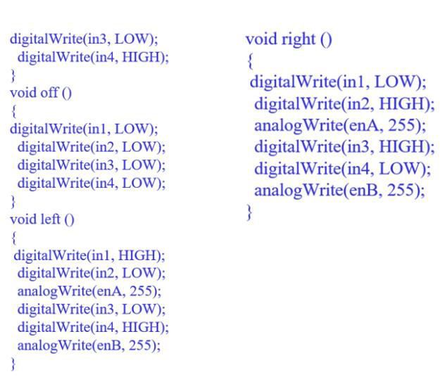
International Journal of Innovative Research in Science, Engineering and Technology (IJIRSET)

                         | e-ISSN: 2319-8753, p-ISSN: 2320-6710| www.ijirset.com | Impact Factor: 7.512|

                                   || Volume 10, Issue 2, February 2021 ||

                                   DOI:10.15680/IJIRSET.2021.1002068
                                                IV. METHODOLOGY

           V. DESIGN OF THE PROGRAMMED GRASS TRIMMERAND CODING OFARDUINO

The design for the programmed grass trimmer is shown in the figure 2, which is drawn by CAD Software.

                  FIGURE 2 CAD 3D DIAGRAM O F PRO GRAMMED GRASS TRIMMER AND BLADE

IJIRS ET © 2021                             |    An IS O 9001:2008 Certified Journal |                     1088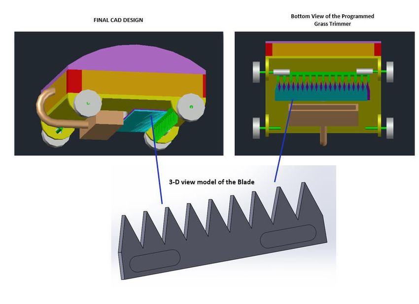
International Journal of Innovative Research in Science, Engineering and Technology (IJIRSET)

                          | e-ISSN: 2319-8753, p-ISSN: 2320-6710| www.ijirset.com | Impact Factor: 7.512|

                                    || Volume 10, Issue 2, February 2021 ||

                                    DOI:10.15680/IJIRSET.2021.1002068

                          FIGURE 3 CAD 2 D DIAGRAM O F PRO GRAMMED GRASS TRIMMER
  Figure 3 shows the 2D images of d ifferent views of the programmed grass trimmer which is drawn in auto CA D.
This image clearly explains about the grass trimmer and the specified parts in it depicts the working of the trimmer.

                                            VI. MO RPHO LO GICAL CHART

Morphological chart is a technique to create ideas in an analytical and systematic manner. Usually, functions of
theproduct are taken as a starting point. Here, in this research work morphology chart is given below to specify the
types of materials to be used for specified parts. Table 1 shows the morphological chart.

                                     TABLE 1 MORPHOLOGICAL CHART

              Functions                                                   Options
  Base
                                  Wood                     Aluminium             Steel              Polymer
  (Chassis)
  Control                         Bluetooth                Wi-Fi                 Remote control     Wired
  Automation
                                  Arduino                  Raspberry Pi          Orange Pi          Banana Pi
  (Microcontrollers)
  Wheels                          Castor wheel             Tanker wheel          Normal wheel

  Motor                           DC motors                AC motors             Stepper motor      Servo motor

  Blade                           Rotary type              Spiral type           Trimmer type

IJIRS ET © 2021                               |   An IS O 9001:2008 Certified Journal |                         1089
International Journal of Innovative Research in Science, Engineering and Technology (IJIRSET)

                             | e-ISSN: 2319-8753, p-ISSN: 2320-6710| www.ijirset.com | Impact Factor: 7.512|

                                         || Volume 10, Issue 2, February 2021 ||

                                        DOI:10.15680/IJIRSET.2021.1002068

                                                                  Ultrasonic
   Sensors                             IR sensor                                         PIR Sensor
                                                                sensor

   Collection of mown grass            Manual                     Vacuum setup           Collecting bag

   Power                               Manual power               Electric Battery       IC engine

   Type of cutting action              Shearing                   Trimming

                                      Adjustable       height
   Additional features
                                   setup
 PUGH MATRIX
         Table 2 shows the PUGH mat rix. The Pugh matrix is a tool used to enable a disciplined, team-based procedure for
         concept generation and selection. Several concepts are assessed rendering to their strengths and weaknesses
         against a reference concept called the datum. By analysing PUGH matrix current research model plays a
         significant role and it was selected.

                                                       TABLE 2 PUGH MATRIX

                                                                                 Concepts
Criteria                                                  IC engine      l awn     Automatic         l awn      Programmed grass
                                   Conceptual
                                                        mower                    mower                       trimmer (Our model)

Base (Chassis)                     S                      +                          +                         -

Automation                         S                      -                          +                         +
Power                              S                      -                          +                         +

Control                            S                      +                          -                         +
Wheels                             S                      +                          -                         -
Blade                              S                      -                          -                         +

Obstacle detection                 S                      -                          +                         +

Compatibility                      S                      -                          +                         +
Light weight                       S                      -                          +                         +

Weight lift capacity               S                      +                          -                         +

Path detection                     S                      +                          -                         +
Stability                          S                      +                          +                         +

Safety                             S                      -                          -                         +

Height adjustment                  S                      -                          -                         +

Comb attachment                    S                      -                          -                         +

Vacuum setup                       S                      -                          -                         +

 IJIRS ET © 2021                                   |    An IS O 9001:2008 Certified Journal |                           1090
International Journal of Innovative Research in Science, Engineering and Technology (IJIRSET)
| e-ISSN: 2319-8753, p-ISSN: 2320-6710| www.ijirset.com | Impact Factor: 7.512|
|| Volume 10, Issue 2, February 2021 ||
DOI:10.15680/IJIRSET.2021.1002068
Total ‘+’ 0 6 7 14
Total ‘- ‘ 0 10 9 2
Total score 0 -4 -2 12
SWOT ANALYSIS
SWOT analysis (or SWOT matrix) is a tactical p lanning method used to help a person or organizat ion find strengths,
weaknesses, opportunities, and threats related to business competition or project planning. SWOT analysis is shown in
table 3
TABLE 3 SWOT ANALYSIS
STRENGTH WEAKNESS
Using Arduino
Cannot connect with IOT
Trimmer type blade (New model)
(usage of blue tooth)
Using comb attachment
Usage in wet land is
Height adjustments
prohibited (using wood as
Automatic control over blue tooth
chassis)
Vacuum setup
OPPORTUNITY THREATS
Changing connection through Wi-Fi enables
to connect with IOT.
The vacuum setup may not
Can add automatic control for height
perform well.
adjustment.
Sensors may throw error or
Changing chassis material will extend the
could not differentiate
area if usage.
between grass and obstacles.
Attaching camera fo r obstacle detection.
(instead of sensors)
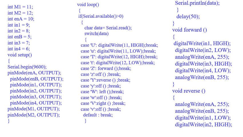
VII. CODING OF THE PROGRAMMED GRASS TRIMMER
IJIRS ET © 2021 | An IS O 9001:2008 Certified Journal | 1091International Journal of Innovative Research in Science, Engineering and Technology (IJIRSET)
| e-ISSN: 2319-8753, p-ISSN: 2320-6710| www.ijirset.com | Impact Factor: 7.512|
|| Volume 10, Issue 2, February 2021 ||
DOI:10.15680/IJIRSET.2021.1002068
VIII. CONCLUS ION
1. Programmed Grass Trimmer has been designed using Auto CAD software and prototype has been made.
2. A different type of blade was attached when compared to any other mower.
3. Testing was done and it cuts grasses at equal height and has the capacity to collect and store the grass.
4. Our invention is main ly to feed cattle the mown grass and has been successfully done and hence the mown
grassdoesn't go to the garbage.
5. Morphological chart, PUGH analysis, SWOT analysis have been done in order to evaluate the concepts drawn.
REFERENCES
1. Tony, Tabac. "Rake attachment for lawn mowers." U.S. Patent 2,794,309, issued June 4, 1957.
2. Douglas, Donald R. "Comb attachment for lawnmowers." U.S. Patent 3,385,041, issued May 28, 1968.
3. Smith, William R. "Height adjustment mechanism fo r lawn mowers." U.S. Patent 3,269,100, issued August 30,
1966.
4. Chen, Sheng K., Shi Y. Horng, and I-Ting Chen. " Robotic lawn mo wer." U.S. Patent 4,694,639, issued September
22, 1987.
5. Martin, Robert L. "Automated lawn mower or floor polisher." U.S. Patent 4,887,415, issued December 19, 1989.
6. Aponte-Roa, Diego A., Xav ier Co llazo, M iguel Goenaga, Albert A. Espinoza, and Kasandra Vazquez.
"Development and evaluation of a remote controlled electric lawn mo wer." In 2019 IEEE 9th Annual Computing
and Communication Workshop and Conference (CCWC) , pp. 1-5. IEEE, 2019.
IJIRS ET © 2021 | An IS O 9001:2008 Certified Journal | 1092You can also read