Volume 6 Environmental Statement (Volume B) Chapter 3: Project Description Application Document: 6.2 - Planning ...
←
→
Page content transcription
If your browser does not render page correctly, please read the page content below
Southampton to
London Pipeline Project

Volume 6
Environmental Statement (Volume B)
Chapter 3: Project Description
Application Document: 6.2
Planning Inspectorate Reference Number: EN070005
APFP Regulation No. 5(2)(a)
Revision No. 1.0
May 2019
(This page is intentionally left blank)
Southampton to London Pipeline Project
    Environmental Statement
    Chapter 3: Project Description

Contents
3      Project Description........................................................................................................................... 1
3.1    Introduction ......................................................................................................................................... 1
3.2    Description of the Replacement Pipeline ........................................................................................... 3
3.3    Description of Each Section ............................................................................................................... 7
3.4    Construction of the Replacement Pipeline ....................................................................................... 14
3.5    Operation of the Replacement Pipeline............................................................................................ 27
3.6    Decommissioning of the Replacement Pipeline ............................................................................... 28
3.7    References ....................................................................................................................................... 28

                                                                                                                                         Page i of Chapter 3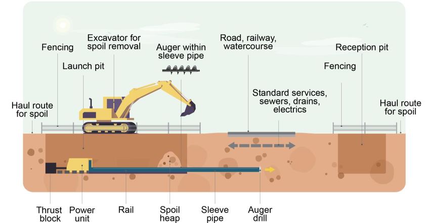
Southampton to London Pipeline Project
 Environmental Statement
 Chapter 3: Project Description

3       Project Description
3.1     Introduction
3.1.1   This chapter provides a description of the development for the purposes of identifying
        and assessing the potential environmental impacts of the development in technical
        assessment Chapters 7 - 15 of Volume 2 of the Environmental Statement (ES).

3.1.2   The development is shown within the Works Plans and Land Plans that accompany
        the application for development consent.

3.1.3   In accordance with the EIA Regulations, the physical characteristics of the
        development are described within this chapter, together with its land use requirements;
        proposed access arrangements; landscaping strategy; utility arrangements; and
        estimated emissions, residues and (soil) arisings.

3.1.4   A description of the Order Limits is provided in Chapter 1 Introduction, with more
        detailed descriptions provided in each technical chapter within Volume 2 of the ES and
        is therefore not repeated here.

3.1.5   The project description provided within this chapter is the final form of the project taken
        to Development Consent Order (DCO) application (the application for development
        consent), and therefore it is possible that the appointed contractor(s) may diverge from
        the design and installation/construction methods described, within the limitations of the
        consenting process. However, in the event that such divergence occurs, it is
        anticipated that adherence to the terms of the consent would avoid the environmental
        effects being any worse than those associated with the final form of the project taken
        to DCO application.

3.1.6   Taking the existing pipeline out of service, known as decommissioning, is covered by
        the original pipeline consent and therefore does not form part of this project. The
        existing pipeline would be decommissioned once the replacement pipeline is
        operational. The nature of the pipeline network means that at no point can both
        pipelines be operational at the same time.

3.1.7   Appendix 3.1 Table of Trenchless Crossings describes the specialist trenchless
        crossing techniques that would be used, such as auger bore and horizontal directional
        drilling (HDD). Appendix 3.2 Proposed Construction Schedule provides an illustrative
        schedule for installation of the replacement pipeline.

3.1.8   This chapter contains a number of project commitments to reduce impacts on the
        environment. These are indicated by a reference number, for example (O1). All
        commitments are listed within the Register of Environmental Actions and
        Commitments (REAC). Further details can be found in Chapter 16 Environmental
        Management and Mitigation.

3.1.9   The following terms are used within this ES:
        • Order Limits: The outer limits for the project, including the route and any temporary
          working areas that would be required to install the pipeline, such as access routes,
          and working compounds. This would also include the easement strip (extending 3m
                                                                                 Page 1 of Chapter 3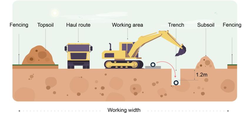
Southampton to London Pipeline Project
 Environmental Statement
 Chapter 3: Project Description

           either side of pipeline) that would be protected along the pipeline following
           installation.
         • Limits of Deviation (LoD): These limits show the maximum area within which the
           pipeline could be installed. This flexibility is required in order to deal with unforeseen
           circumstances, such as ground conditions and local features.
         • Working Width: The width required within the Order Limits to install the pipeline. It
           does not include any working compounds, laydown areas, stringing out areas or off-
           site access roads.
         • Temporary construction compounds and laydown areas: These are small satellite
           areas close to the route that are used for storing equipment, hosting staff facilities,
           and laying down pieces of the pipeline.
         • Temporary trenchless construction stringing out areas: These areas are used to
           weld segments of the pipeline together above the ground.
         • Temporary construction site access roads: These are temporary roads for
           machinery and vehicles. They are used to provide access to the highway from the
           work sites to reduce the impact on local roads.
         • Temporary logistics hubs: These are areas which may be remote from the route of
           the replacement pipeline, that would be used for pipe storage and distribution as
           well as providing site offices, welfare and storage facilities.
         • Narrow Working: This approach involves the contractor(s) using less space than
           standard working width due to localised constraints, such as working in roads or
           ecologically sensitive areas.

         Design Resilience to Climate Change

3.1.10   The pipeline itself would be buried underground with a minimum depth from the top of
         the pipe to the ground surface of 1.2m, including under the bed of watercourses. This
         provides protection from climate change effects such flood events or other extreme
         weather events. The above ground components, such as the pigging station, pipeline
         markers and Cathodic Protection (CP) cabinets are, through design and materials
         considered resilient to climate change effects.

3.1.11   The flood resilience of the project is covered within the Flood Risk Assessment
         (application document 7.3) and Chapter 8 Water, where there is an assessment of
         the potential impacts and the proposed mitigation measures. Due to the short-term
         duration of installation, it has been agreed with the Environment Agency, that climate
         change impacts are scoped out of the assessment. There are no further impacts of
         climate change on the project anticipated during installation.

3.1.12   The pigging station is located in Flood Zone 1 and therefore consideration of climate
         change is not required.

3.1.13   It is concluded that the project overall is resilient to climate change over the 60 year
         design life.

                                                                                  Page 2 of Chapter 3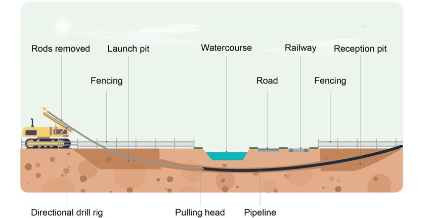
Southampton to London Pipeline Project
 Environmental Statement
 Chapter 3: Project Description

3.1.14   The effects of the project on climate change are addressed in Appendix 13.1, Technical
         Note on Air Quality, which includes consideration of greenhouse gas emissions from
         construction traffic.

3.2      Description of the Replacement Pipeline
         Below Ground Pipe

3.2.1    Esso Petroleum Company, Limited (Esso) intends to replace 90km (56 miles) of its
         105km (65 miles) long aviation fuel pipeline that runs from its Fawley Refinery near
         Southampton to its West London Terminal storage facility in Hounslow. The
         replacement pipeline is 97km (60 miles) long, taking into account that it cannot follow
         the line of the existing pipeline along its whole length due to new developments and
         environmental constraints.

3.2.2    The replacement pipeline starts near Boorley Green at the end point of the previously
         replaced pipeline. The route runs generally in a northeast direction via the Pumping
         Station in Alton. It terminates at the West London Terminal storage facility. The layout
         of the project is presented in Figure 3.1.

3.2.3    The installed pipe would have a nominal internal diameter of 30cm and a nominal wall
         thickness of 11.9 mm. The wall thickness is greater than British Standard PD8010
         (British Standards Institution, 2019) to provide additional long-term protection from
         deterioration or damage.

3.2.4    The replacement pipeline would be buried underground for its entire length. The
         minimum depth from the top of the pipe to the ground surface would be 1.2m in open
         cut sections, and deeper for trenchless crossings. This is reflected in the engineering
         designs. A slightly shallower depth may conceivably be necessary in exceptional
         circumstances, but all indications are that this would not be required. The pipeline
         would also be buried deeper, typically 1.5m from top of pipe to ground surface, in roads
         and streets to account for other existing infrastructure such as utility pipes, cables and
         sewers.

3.2.5    Where the replacement pipeline is routed adjacent to Esso’s existing pipelines, the
         Order Limits are generally 36m wide to provide flexibility for detailed routeing and
         construction methodologies for pipeline installation adjacent to these existing
         pipelines. Where the replacement pipeline moves away from the existing pipelines the
         Order Limits are 30m wide. A wider working width may be required at some locations,
         for example, the Order Limits are wider where the geology requires more working area.
         Where specific width restrictions exist, for example for highway works or sensitive
         ecological areas, the working width would be narrowed. To reduce vegetation loss, the
         project includes an overarching commitment to only utilise a 10m width when crossing
         through boundaries between fields where these include hedgerows, trees or
         watercourses (O1).

3.2.6    Open cut trenching methods would be used for the majority of the route. For crossings
         of A roads and motorways (including the M25 and M3) and other heavily trafficked
         roads, railways (including main and branch lines) and some watercourses (including
         the River Thames), specialist trenchless techniques such as auger bore and horizontal
         directional drilling (HDD) would be used (Appendix 3.1 Table of Trenchless Crossings).
                                                                                 Page 3 of Chapter 3
Southampton to London Pipeline Project
Environmental Statement
Chapter 3: Project Description
At these locations additional working space would be required and therefore the Order
Limits have been widened.
Pigging Station near Boorley Green
3.2.7 Pigging stations allow the insertion and withdrawal of pipeline inspection gauges
(PIGs) into and out of the pipeline. A new pigging station would be constructed, with
the preferred location being southwest of Netherhill Lane between Boorley Green and
Durley. The pigging station would contain valves, a PIG receiver and a PIG launcher.
3.2.8 The pigging station would be provided with power and telecoms. The pigging station
would be located within a fenced compound approximately 23m x 30m in size
(excluding its access track) with secure fencing up to 3m high incorporating a double
access gate for vehicles. The compound would be provided with manually operated
lighting for when the station is operated in low light conditions. It would not be
permanently lit.
3.2.9 A very small amount of aviation fuel is removed from the pipe during pigging. The
Pigging Station is designed to safely and securely capture such discharges during
pigging operations and would be removed by tanker for disposal.
Valves
3.2.10 Fourteen remotely operated valves would be installed along the route of the
replacement pipeline to allow isolation for maintenance or to limit the impact of a
potential leak. The valves would be remotely operated from the pipeline control centre
located at the West London Terminal storage facility. The valve locations can be found
on Figure 3.1.
3.2.11 There is also a single Pressure Transducer (PT). The pressure transducer’s primary
purpose is to monitor pressure.
3.2.12 Twelve of the valves and the PT would be installed below ground level in chambers,
with only limited above ground visible elements including secure chamber access
covers with associated handrail and a control cabinet.
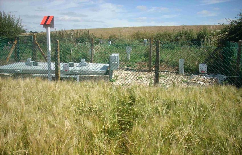
3.2.13 Each chamber would be located within an enclosure. Typically, the maximum
dimensions of the enclosure would be approximately 7m x 5m in size, with secure
fencing up to 2.4m high incorporating up to two pedestrian access gates. The
enclosures would not be lit. Photograph 3.1 provides an illustration of a valve
enclosure.
Page 4 of Chapter 3Southampton to London Pipeline Project
Environmental Statement
Chapter 3: Project Description
Photograph 3.1: An Existing Valve Enclosure and Flight Marker Post
Cathodic Protection (CP)
3.2.14 The Cathodic Protection (CP) system currently helps protect the existing pipeline
against corrosion. Most elements of the CP system, including cabling and ground beds,
are buried below ground and are not visible. The ground beds for the existing pipelines
would be used as part of the CP system for the replacement pipeline.
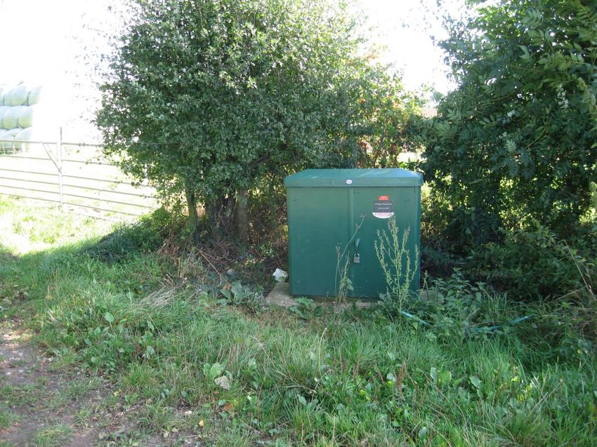
3.2.15 Six above ground CP transformer rectifier cabinets would be needed close to the
replacement pipeline to supply power to the CP system. The CP cabinet locations can
be found on Figure 3.1. Where possible the cabinets for the existing pipeline would be
refurbished and reused and internal components replaced.
3.2.16 The CP transformer rectifier cabinets would be powered by connections to existing
electrical supplies associated with the CP system for the existing pipeline Photograph
3.2 shows a typical CP transformer rectifier cabinet.
3.2.17 The CP system includes small above ground industry standard CP test posts, which
are installed approximately every 1km along the existing pipeline route, usually placed
directly above the pipeline to a maximum height of 1.2m. The colour, appearance and
size of a typical CP test post are very similar to that of a pipeline marker post (as
described below).
Page 5 of Chapter 3Southampton to London Pipeline Project
Environmental Statement
Chapter 3: Project Description
Photograph 3.2: An Existing CP Transformer Rectifier Cabinet
Pipeline Markers
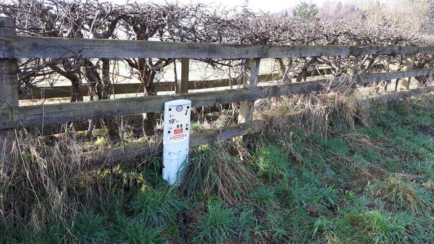
3.2.18 The replacement pipeline would be marked at intervals along the pipeline and at all
watercourse, railway and road crossings and boundaries by installing new industry
standard marker posts. In the absence of the above, the spacing of the marker posts
would vary according to location. The maximum spacing would typically range from
every 500m in rural areas to every 50m in high density residential areas, however,
markers would need to be located such that ideally each adjacent marker is visible
from any location along the pipeline. Photograph 3.3 shows a typical example of an
industry standard marker post.
3.2.19 The route of the replacement pipeline would also be marked with new red and black
colour-coded flight marker posts at a frequency of about 500m. These would be for
use when the pipeline is inspected by helicopter and would be positioned at field
boundaries where possible.
Page 6 of Chapter 3Southampton to London Pipeline Project
Environmental Statement
Chapter 3: Project Description
Photograph 3.3: Typical Industry Standard Marker Post
Installation of a Replacement Booster Pump at Alton Pumping Station
3.2.20 The replacement pipeline would be routed through the existing Alton Pumping Station,
where it would connect to existing infrastructure and a proposed new booster pump to
continue fuel supply to London Gatwick Airport. There are currently three existing
external pumps at Alton Pumping Station. The project includes installing a single
replacement external pump near to the existing pumps. A small amount of additional
above ground pipework would be installed for the tie-ins to the replacement pump.
Modification of Existing Pigging Station at the West London Terminal Storage
Facility
3.2.21 The existing pigging station at the West London Terminal storage facility would be
modified, including installation of a new PIG receiver. The works would include minor
changes to alignment of pipework within the pigging station, renewal of equipment and
some positional change. However, the existing pipework and PIG receiver would
become redundant and would be removed, with the result that there would be little
change to the location, layout, size and appearance of the pigging station when viewed
from outside the fence line.
3.3 Description of Each Section
3.3.1 To aid design development and environmental assessment, the route was divided into
eight separate sections (Section A to Section H), as follows:
• Section A – Boorley Green to Bramdean
• Section B – Bramdean to South of Alton
• Section C – South of Alton to Crondall
• Section D – Crondall to Farnborough
Page 7 of Chapter 3Southampton to London Pipeline Project
Environmental Statement
Chapter 3: Project Description
• Section E – Farnborough to Bisley and Pirbright Ranges
• Section F – Bisley and Pirbright Ranges to M25
• Section G – M25 to M3
• Section H – M3 to West London Terminal storage facility
3.3.2 The eight sections are shown on Figure 3.1.
Section A – Boorley Green to Bramdean
Summary of Section A
3.3.3 Section A (Figure 3.1, Sheets 1 - 4) is largely rural and runs through agricultural land.
Most of this section is within the South Downs National Park (SDNP). It spans Eastleigh
Borough and Winchester City Council. As the replacement pipeline would have a larger
diameter than the existing pipeline south of Boorley Green, a pigging station would be
required southwest of Netherhill Lane between Boorley Green and Durley.
Route Description
3.3.4 Section A is approximately 20km (12 miles) long and starts just south of Maddoxford
Lane to the east of Boorley Green. The Application route (‘the route’) heads east
alongside Maddoxford Lane before crossing Maddoxford Lane and heading north
across open land, then crosses Ford Lake Stream. The section then crosses the B2177
between Bishop’s Waltham and Upham, where it enters the SDNP. The route diverts
away from the existing pipeline to avoid the chalk grassland and established vegetation
areas at Stephen’s Castle Down. The route passes Joan’s Acre Wood, then passes
the village of Bramdean, before this section ends just after crossing the A272.
Sub-options in Section A
3.3.5 In this section, there is one part of the route in the area around Hinton Ampner that still
include sub-options. There are two sub-options just east of Joan’s Acre Wood,
designed to take account of sites of environmental and cultural importance in the area:
• The A2a sub-option passes Joan’s Acre Wood, avoiding Brockwood Copse and
Roadside Strips Site of Importance for Nature Conservation (SINC) before heading
northwest past Malthouse Plantation. This option is routed through the Hinton
Ampner National Trust estate.
• The A2b sub-option passes underneath Brockwood Copse and Roadside Strips
SINC before heading northwest past The Firs and Godwin’s Plantation. The eastern
option is routed around the Hinton Ampner National Trust estate. It then re-joins the
western sub-option.
Use of Trenchless Installation Techniques
3.3.6 As detailed within Appendix 3.1 Table of Trenchless Crossings, trenchless installation
techniques are proposed to be used for the following crossings:
• TC 001 – Ford Lake Stream;
• TC 002 – Stakes Lane;
Page 8 of Chapter 3Southampton to London Pipeline Project
Environmental Statement
Chapter 3: Project Description
• TC 003 – Riversdown Road (sub-option A2b only); and
• TC 004 – A272.
Section B – Bramdean to South of Alton
Summary of Section B
3.3.7 Section B (Figure 3.1, Sheets 4 - 6) is also largely rural, similar to Section A, and lies
mainly within the SDNP – with a short section between Monkwood and near Four
Marks outside the SDNP. It spans Eastleigh Borough and Winchester City Councils.
Route Description
3.3.8 Section B is around 15km (9 miles) long and starts just after the A272 crossing. It
avoids Woodcote Copse and Bramdean Common before running north of West Tisted.
It then runs through the Four Marks golf course followed by the crossing of the A32,
before running outside the southern boundary of Chawton House Registered Park and
Garden. The section ends at the boundary of the SDNP after the B3006 crossing.
Use of Trenchless Installation Techniques
3.3.9 As detailed within Appendix 3.1 Table of Trenchless Crossings, trenchless installation
techniques are proposed to be used for the following crossings:
• TC 005 – Petersfield Road; and
• TC 006 – A32.
Section C – South of Alton to Crondall
Summary of Section C
3.3.10 Section C (see Figure 3.1, Sheets 6 - 8) is largely rural with long stretches passing
through agricultural land. It spans East Hampshire and Hart District Council.
Route Description
3.3.11 Section C is approximately 15km (9 miles) long and starts at the boundary of the SDNP
after the B3006 crossing. It deviates slightly from the existing pipeline route to avoid
local businesses. The route runs east of Alton, skirting around Worldham golf course
before crossing Caker’s Lane (B3004). This is followed by a crossing of the River Wey
and the Alton to Waterloo railway line before it approaches Alton Pumping Station.
From Alton Pumping Station the route passes under the A31 and then runs to the
southeast of Upper and Lower Froyle. It avoids Locks Grove and Lee Wood SINC. The
section ends at Dippenhall Street.
Page 9 of Chapter 3Southampton to London Pipeline Project
Environmental Statement
Chapter 3: Project Description
Use of Trenchless Installation Techniques
3.3.12 As detailed within Appendix 3.1 Table of Trenchless Crossings, trenchless installation
techniques are proposed to be used for the following crossings:
• TC 007 – Caker Lane (may be trenchless or open cut - this is still to be determined);
and
• TC 008 & 009 – crossings of the River Wey and Alton to Waterloo railway line, and
the A31 and minor access road respectively.
Section D – Crondall to Farnborough
Summary of Section D
3.3.13 Section D (Figure 3.1, Sheets 8 - 9) runs through both rural and urban areas. There
are two Sites of Special Scientific Interest (SSSI) and a European designated wildlife
site within this Section. This section spans Hart District Council and Rushmoor
Borough Council.
Route Description
3.3.14 Section D is approximately 9km (6 miles) long and starts at Dippenhall Street shortly
after which it crosses Oak Park Golf Course. The section continues, crossing the A287.
It runs alongside Naishes Lane past Quetta Park where it deviates from the existing
pipeline and passes through Wakefords Copse to avoid crossing Fleet Business Park.
After running alongside the B3013 for approximately 300m it passes north of a
development site, before crossing the northern part of Tweseldown Racecourse,
Ewshot, and the Bourley and Long Valley SSSI. At Norris Hill the proposed haul road
diverges from the pipe route in order to utilise an established track. This is followed by
a crossing of the Basingstoke Canal and A323. The route passes along the northern
boundary just outside Eelmoor Marsh SSSI. The section crosses Cody Technology
Park and the western part of the former Southwood Golf Course and finishes just after
the crossing of the A327.
Use of Trenchless Installation Techniques
3.3.15 As detailed within Appendix 3.1 Table of Trenchless Crossings, trenchless installation
techniques are proposed to be used for the following crossings:
• TC 010 – A287 Ewshot Hill;
• TC 011 & 012 – Bourley and Long Valley SSSI (two consecutive trenchless
crossings);
• TC 013 – Basingstoke Canal SSSI and A323; and
• TC 014 – A327 Ively Road.
Section E – Farnborough to Bisley and Pirbright Ranges
Summary of Section E
3.3.16 Section E (see Figure 3.1, Sheets 9 - 10) runs through both rural and urban areas. It
spans Rushmoor Borough Council and Surrey Heath Borough Council.
Page 10 of Chapter 3Southampton to London Pipeline Project
Environmental Statement
Chapter 3: Project Description
Route Description
3.3.17 Section E is approximately 9km (5 miles) long and starts just after the A327 crossing.
It runs north through the western section of the former Southwood Golf Course and
then through open land to the west of Cove Brook. It then runs along Cove Road
(B3014) for a short distance and then along Nash Close before crossing the South
Western main railway line. After the railway crossing the section runs east alongside
the railway line to Stakes Lane and then along the southern boundary of the allotments
located off Prospect Road.
3.3.18 Due to the restricted space alongside the railway line, trenchless techniques would be
required for much of this length.
3.3.19 The section then continues east through Queen Elizabeth Park, followed by a crossing
of the A325. The section then crosses the grounds of Farnborough Hill School, after
which it would cross the North Downs railway line, A331, River Blackwater, Blackwater
Valley and the Ascot to Guildford railway line. It then runs along the southeastern
boundary of SC Johnson Ltd land before crossing Frimley Green Road (B3411) near
the roundabout with Balmoral Drive. From the B3411 the route follows Balmoral Drive
to Frith Hill, where it follows the existing pipeline across Pine Ridge Golf Course. This
section finishes immediately after the B3015 at the junction of Old Bisley Road, The
Maultway and Deepcut Bridge Road.
Use of Trenchless Installation Techniques
3.3.20 As detailed within Appendix 3.1 Table of Trenchless Crossings, trenchless installation
techniques are proposed to be used for the following crossings:
• TC 015 – South Western Main railway line;
• TC 016 – Cove Brook;
• TC 017 & 018 – North side of railway embankment: Two consecutive trenchless
crossings are proposed on the north side of the South Western Main railway line,
parallel to West Heath Road and adjacent to the railway embankment;
• TC 019 – A325 Farnborough Road; and
• TC 020 – Blackwater Valley trenchless crossing of the North Downs railway line, the
A331, River Blackwater, and Ascot to Guildford railway line (the crossing of the
remaining elements of the Blackwater Valley may be trenchless or open cut – this
is still to be determined).
Section F – Bisley and Pirbright Ranges to M25
Summary of Section F
3.3.21 Section F (Figure 3.1, Sheets 10 - 12) runs through both rural and urban areas,
including two SSSIs. It spans Surrey Heath Borough Council and Runnymede Borough
Council.
Route Description
Page 11 of Chapter 3Southampton to London Pipeline Project
Environmental Statement
Chapter 3: Project Description
3.3.22 Section F is approximately 17km (11 miles) long and starts immediately after the
B3015, where it passes adjacent to the Bisley and Pirbright Ranges. It runs north
adjacent to The Maultway (B3015) then turning east to follow Red Road (B311) and
through an area of woodland. The section then crosses Guildford Road and the A322
Lightwater Bypass, continuing through the former Windlemere golf course. It then
continues generally northeast, crossing the Hale Bourne and Windlesham Road,
before passing through Chobham Common SSSI and Foxhills golf course to the B386.
The section then crosses the B386 and continues north of St Peter’s Hospital. It passes
under the A320, through the grounds of Salesian School and under the M25.
Use of Trenchless Installation Techniques
3.3.23 As detailed within Appendix 3.1 Table of Trenchless Crossings, trenchless installation
techniques are proposed to be used for the following crossings:
• TC 021 – A322 Lightwater Bypass;
• TC 022 – Hale Bourne watercourse;
• TC 023 – Windlesham Road (may be trenchless or open cut – this is still to be
determined);
• TC 024, 025 and 026 – Three trenchless crossings within Chobham Common SSSI;
• TC 027 – Accommodation Road;
• TC 028 – Holloway Hill woods;
• TC 029 – Hardwick Lane; and
• TC 030 – A320 Guildford Road, Salesian School grounds and the M25.
Section G – M25 to M3
Summary of Section G
3.3.24 Section G (Figure 3.1, Sheets 12 - 13) is largely urban, but also includes a SSSI. It
spans Runnymede Borough Council and Spelthorne Borough Council.
Route Description
3.3.25 Section G is around 4km (3 miles) long and starts after the trenchless crossing of the
A320/M25, before continuing through Abbey Moor golf course. There is then a crossing
of the Chertsey Branch railway line between Chertsey and Addlestone Stations. It then
follows Cranford Drive before crossing the A317 Chertsey Road and subsequently
passing through the playing fields at Addlestone Moor. The section then crosses the
Chertsey Bourne before heading towards the River Thames. The route diverts away
from the existing pipeline crossing of the Thames to avoid Dumsey Meadow SSSI,
which lies just north of the river. The trenchless crossing of the River Thames would
continue under the B375 and Old Littleton Lane. The section ends at the M3 Motorway
west of Littleton Lane.
Use of Trenchless Installation Techniques
Page 12 of Chapter 3Southampton to London Pipeline Project
Environmental Statement
Chapter 3: Project Description
3.3.26 As detailed within Appendix 3.1 Table of Trenchless Crossings, trenchless installation
techniques are proposed to be used for the following crossings:
• TC 031 – Chertsey Branch railway line;
• TC 032 – A317 Chertsey Road;
• TC 033 – Chertsey Bourne;
• TC 034 – River Thames and B375 Chertsey Bridge Road; and
• TC 035 – M3.
Section H – M3 to the West London Terminal Storage Facility
Summary of Section H
3.3.27 Section H (Figure 3.1, Sheets 13 - 14) is largely urban. It spans Spelthorne Borough
Council and ends just within the London Borough of Hounslow.
Route Description
3.3.28 Section H is around 8km (5 miles) long and starts after the crossing of the M3,
proceeding north, before crossing the B376 Shepperton Road. The proposed River
Thames flood alleviation scheme would also cross the route in this area.
3.3.29 The section then heads north to cross the Queen Mary Intake Canal before following
Ashford Road (B377) west of the Queen Mary Reservoir. This is followed by a crossing
of the Staines Reservoir Aqueduct and Ashford Road just south of the A308.
3.3.30 The section then passes through Fordbridge Park before crossing the Staines Bypass
(A308).
3.3.31 After crossing the A308, it continues north adjacent to and along Woodthorpe Road,
crossing the Waterloo to Reading railway line just east of Ashford Station. This would
be accomplished by heading east to cross Church Road (B378) into the grounds of
Clarendon Primary School and then crossing the railway line heading north.
3.3.32 The section passes on the east side of the grounds of St James Senior Boys’ School
and through the eastern part of the Thomas Knyvett College playing fields before
crossing under the A30. The route finishes at the Esso West London Terminal storage
facility in Hounslow.
Use of Trenchless Installation Techniques
3.3.33 As detailed within Appendix 3.1 Table of Trenchless Crossings, trenchless installation
techniques are proposed to be used for the following crossings:
• TC 036 – B376 Shepperton Road;
• TC 037 – Queen Mary Reservoir Intake Canal;
• TC 038 – Staines Reservoir Aqueduct and B377 Ashford Road;
• TC 039 – Staines Bypass A308, River Ash and Woodthorpe Road;
• TC 040 – B378 Church Road;
Page 13 of Chapter 3Southampton to London Pipeline Project
Environmental Statement
Chapter 3: Project Description
• TC 041 – Waterloo to Reading Railway Line; and
• TC 042 – Staines Road A30.
3.4 Construction of the Replacement Pipeline
Construction Schedule
3.4.1 An illustrative Construction Schedule is provided in Appendix 3.2.
3.4.2 Works to install and commission the pipeline are expected to start from grant of DCO
and be completed early 2023. Certain advance works may take place prior to
development consent where consented under alternative regimes, for example, the
Town and Country Planning Act 1990.
3.4.3 The construction schedule has yet to be developed in detail, as this would be
undertaken during the detailed design stage. For the purposes of assessment, a short-
term duration is assumed to be less than six months based on the criteria set out in
Table 3.1 and includes mobilisation and reinstatement.
3.4.4 The construction of the new pigging station near to Boorley Green is anticipated to be
undertaken through 2021 and would take up to four months to build.
3.4.5 Connections to the existing CP systems, valves and associated infrastructure would
be installed whilst the pipeline is being laid as they are an integral part of the pipeline.
3.4.6 Marker posts would be erected after reinstatement.
3.4.7 Throughout the installation of the pipeline there would be a number of work fronts. A
work front is a specific area or location where a crew, generally comprising up to 10
construction workers, are carrying out a particular aspect of the main pipeline
construction activities, including topsoil stripping, trench excavation, pipe installation
and backfilling of trenches. There may be several work fronts operating
simultaneously. Each work front would typically continue in the same direction, south
to north, but starting from a different point.
3.4.8 Trenchless techniques are proposed in a number of locations. The duration of such
techniques varies according to the length of the pipe being installed and the technique
used. For example, with horizontal directional drilling (HDD), the construction of a
100m long crossing would take around four to five weeks, with a further two weeks
required per 100m increase in the length of the crossing. This also assumes that the
works to install trenchless crossings would not be unduly restricted with regards to
working hours and weather conditions. Certain activities would require continual 24
hour working, for example the pipe pulling phase for a HDD. If working hours for
trenchless crossings are restricted, then the installation would take longer.
3.4.9 The construction schedule is based on a number of key assumptions for pipeline
installation in differing terrain. These assumptions are presented in Table 3.1.
Page 14 of Chapter 3Southampton to London Pipeline Project
Environmental Statement
Chapter 3: Project Description
Table 3.1: Key Working Assumptions
Assumption Open Areas Urban Areas
Pipe length laid per week 450m 90m
Excavated spoil off-site Limited Yes
Standard construction working Monday – Saturday 07:00 to 19:00
Typical pipe lengths 12m 3-6m
Road closures for open cut pipeline Up to three working days, Class B roads and lower.
crossings of carriageways
Traffic management Traffic signals to be provided where pipe is laid along or
adjacent to carriageways.
Mostly two-way working.
Construction Environmental Management Plan
3.4.10 A Construction Environmental Management Plan (CEMP) would be produced in line
with the Outline CEMP. It would explain how the activities of sub-contractor(s) comply
with its requirements and include subsidiary plans such as the management of waste
and soils (G1). The Outline CEMP is found in Appendix 16.2 and would be expected
to comply with the Code of Construction Practice (CoCP) (Appendix 16.1).
3.4.11 The contractor(s) would provide a series of reviewed methodologies. The number of
construction activities subjected to this process would be decided on a risk-based
approach and could include site preparation, pipe-laying, trenchless crossings and
reinstatement. Each methodology would include the measures that need to be
undertaken to meet the requirements outlined in the CEMP. Methodologies would be
reviewed and accepted by the Employer’s Representative (G2).
Construction Phase Activities
3.4.12 Typical pre-installation activities are summarised in this section.
Route Survey, Setting Out and Record of Condition
3.4.13 Photographic records would be compiled during route surveys and setting out of the
works. Detailed records of the condition of the roads in the vicinity of the route would
be made. Photographic records would also be taken of features that are likely to be
affected by the project.
Utility Diversions
3.4.14 Surveys to establish the full extent of underground services and public utilities would
be undertaken prior to commencing works.
Page 15 of Chapter 3Southampton to London Pipeline Project
Environmental Statement
Chapter 3: Project Description
Working Area Preparation
3.4.15 All working areas would need to be prepared prior to installation of the pipeline. This
would generally consist of:
• Erecting advance warning signs at road crossings;
• Opening the entrance to the working area through field boundaries;
• Making sure that services are well protected where the access/egress to
compounds are created;
• Erecting ‘goal post’ protection and location/warning notices where overhead cables
are present. These govern the height at which plant can pass safely underneath;
• Opening entrances to subsequent field boundaries;
• Installing temporary watercourse crossings to maintain uninterrupted flows;
• Pruning and protecting trees; and
• The location of all known buried services would be identified, marked and surveyed,
including digging of trial holes where appropriate. Location/warning notices would
be erected for all known services.
Temporary Fencing
3.4.16 Working areas would be appropriately fenced. The choice of fencing would be decided
following a risk assessment, relevant to the work location. Specific areas such as
compounds may require additional security measures such as lighting, security guards
or CCTV (G85).
3.4.17 Within all urban areas, and areas where an interface with the general public is
anticipated, the use of either strong wall or block and mesh fencing e.g. HERAS
fencing would be used. If the area is near a school, or on a pedestrian route to a school,
double thickness fencing that has been multi-clipped may be used.
3.4.18 In some locations the fence used may also serve to provide acoustic and visual
screening of the work sites and reduce the potential for disturbance of users in the
surrounding areas (G85).
3.4.19 Provision of additional fencing on a site by site basis may be used to reduce the
potential for impacts on wildlife and trees. Fencing would be regularly inspected and
maintained and removed as part of the demobilisation unless otherwise specified
(G85). When working within a field environment, fencing requirements would be
discussed with the landowners. This would determine what kind of fencing would be
required, on a field-by-field basis.
Pre-Construction Drainage
3.4.20 Runoff across the site would be controlled by the use of a variety of methods including
header drains, buffer zones around watercourses, on site ditches, silt traps and
bunding (G11). Reinstatement of any existing land drains once the pipeline
construction has been completed forms part of land reinstatement as described below.
Page 16 of Chapter 3Southampton to London Pipeline Project
Environmental Statement
Chapter 3: Project Description
Temporary Access for Construction
3.4.21 Temporary access tracks would be provided to link the pipeline construction areas to
the local road network. Where new or additional surfacing is required on any access
tracks and compound areas, these would be permeable surfaces where ground
conditions allow (G126). Where these temporary access tracks are across open
ground, the topsoil would be stripped and the access track constructed by treating the
subsoil with a soil binder or laying the track with stone on a geotextile membrane or
timber bog mats.
3.4.22 The access tracks would be fenced and gated to aid control of vehicle access between
the construction areas and the local road network.
Logistics Hubs
3.4.23 Six logistics hubs would be established in locations, close to the strategic road network
before commencement of the main construction works. The logistic hubs would serve
as points for accepting deliveries and storage of pipe. From the logistics hubs, pipe
sections would be transported directly to the pipe storage areas within the various
temporary construction compounds by lorry. Each of the hubs would provide a pipe
laydown area, secure plant storage area, bunded fuel storage, single-storey offices,
staff welfare facilities and a vehicle parking area.
3.4.24 Key information relating to the six logistics hubs is presented in Table 3.2 (running in
south to north order from the first to the last row of the table):
Table 3.2: Logistics Hubs – Key Information and Assumptions
Logistic Hub Name Approximate Current Land Use
Area (Ha)
A31 Ropley Dean 2.7 Currently in agricultural use as grazing.
A31/A32 Junction Northfield 5.4 This site is in agricultural use as part of a sheep farm for
Lane, Alton winter grazing and silage production in the spring and
summer.
Hartland Park Village, 9.1 This is the site of an ex-military facility, the site has been
Farnborough demolished and cleared of all material. It has outline
planning permission for 1500 homes. These are being
built over the next 15 years.
Ministry of Defence (MoD) land: 1.9 Part of the MoD ranges – the site has a concrete surface
Deepcut Bridge Road, Frimley with some overgrown and self-seeded tree cover.
Green
M3 Junction 3: New Road, 3.3 Currently being vacated and restored following use by
Windlesham Balfour Beatty as a compound for the M3 Smart
Motorway works – therefore the land would be in
agricultural use when Esso commence work.
Brett Aggregates, Littleton Lane, 1.3 The site is currently a mineral extraction site (quarry)
Shepperton including some historical landfill, and is regulated under
an Environmental Permit. The site is being restored to
agriculture with some biodiversity areas including reed
beds. The proposed logistics hub would be located on
the proposed agricultural land.
3.4.25 Where applicable the topsoil would be stripped from the logistics area and stockpiled
around the hub perimeter within the site fence. A stone road and apron would be laid
Page 17 of Chapter 3Southampton to London Pipeline Project
Environmental Statement
Chapter 3: Project Description
on a geotextile membrane to provide an all-weather surface access to the local
highway.
3.4.26 Where viable, the logistics hubs would use temporary connections to existing utility
networks (e.g. sewers, telecoms, power and water). Where these connections are not
viable, self-contained welfare units and generators would be used.
3.4.27 The logistics hubs would require lighting. To provide safety and security low level
lighting would be permanently on during periods of darkness. Lighting would be in
accordance with relevant industry good practice standards and would be documented
within the CoCP. Lighting would be of the lowest luminosity necessary for safe delivery
of each task. It would be designed, positioned and directed to reduce the intrusion into
adjacent properties and habitats (G45).
3.4.28 Over the proposed two-year construction period the estimated number of vehicle
movements to and from the logistics hubs are provided in Table 3.3. Whilst average
daily figures are given, there would be an increase in traffic movements during initial
set up of the hubs.
Table 3.3: Estimated Two-Way Vehicle Movements – Average Number Per Working Day at Each
Logistics Hub
Logistics Hub HGV LGV / Cars
A31 Ropley Dean 7 46
A32/A31 Junction Northfield Lane 13 74
Hartland Park Village, Farnborough 25 150
MoD land: Deepcut Bridge Road, Frimley Green 5 31
M3 Junction 3: New Road, Windlesham 29 159
Brett Aggregates, Littleton Lane, Shepperton 11 74
Construction Compounds
3.4.29 Approximately 52 temporary compounds would be established along the route of the
new pipeline for the storage of pipe, materials, plant and equipment.
3.4.30 The fenced compounds would be accessed from the existing road network and would
include single-storey staff welfare facilities, parking, waste storage, and wheel washing
areas. The temporary compounds would also provide hardstanding areas, with apron
and access areas comprising stone laid on a geotextile membrane.
3.4.31 Compound access points to the public highway would be constructed with temporary
hard surfacing (G16).
3.4.32 Construction compound sizes would vary but would have a fenced area of
approximately 40m x 60m for a typical rural construction compound. 2.4m high
temporary fencing, incorporating both pedestrian and vehicle access gates, would be
installed around the perimeter of each construction compound.
3.4.33 In general, the construction compounds would not be connected to existing utilities,
using self-contained mobile welfare facilities, generators and mobile communications.
Page 18 of Chapter 3Southampton to London Pipeline Project
Environmental Statement
Chapter 3: Project Description
Lighting would be of the lowest luminosity necessary for safe delivery of each task. It
would be designed, positioned and directed to reduce the intrusion into adjacent
properties and habitats (G45).
3.4.34 The construction compounds would be modest in size, for example 40m by 60m. The
exact size and shape would vary depending on site features and conditions.
Public Highways and Public Rights of Way
3.4.35 The works would require road, lane and footpath (pavement) closures and diversions
for reasons of safety and the project would work to limit the impact of these works. Any
work areas would be fenced off with appropriate safety signage and secure fencing.
3.4.36 All designated Public Rights of Way would be identified, and any potential temporary
closures applied for/detailed in the draft DCO. All designated Public Rights of Way
crossing the working area would be managed, including National Trails, with access
only closed for short periods while construction activities occur (G114).
Topsoil Removal and Storage
3.4.37 Where topsoil stripping is required, the normal working practice (where not otherwise
specified within a methodology document) would be to strip full depth of topsoil (where
present) from construction compounds and logistics hubs; access roads; across the
working width; and any other areas to be trafficked. The depth of topsoil strip would
not be expected to exceed 0.3m. Topsoils and subsoils intended for reinstatement
would be temporarily stockpiled as close to where they were stripped from as
practicable (G155), unless the working width is reduced to such an extent that the
topsoil would need to be stored at an alternative location close by. The topsoil would
be reinstated above the subsoil (G154).
Haul Road Construction
3.4.38 Haul roads would be formed through most of the working area. Where soils are
suitable, the haul roads would be formed from the exposed subsoil. Appropriate
techniques would be used when necessary to provide protection for subsoils from
compaction and smearing in areas subject to heavy trafficking. The specific protection
measures and their required locations would be set out in the appointed contractors'
methodology document and agreed between the contractor(s) and overseeing Suitably
Experienced Person (SEP) prior to construction commencing (G157). Appropriate
techniques could include treating the subsoil with a soil binder, laying the track with
inert material on a geotextile membrane or installing timber bog mats.
Pipe Storage and Stringing
3.4.39 Six logistics hubs would be established in locations close to the strategic road network.
The logistic hubs would serve as points for accepting deliveries and storage of pipe.
3.4.40 From the logistics hubs, pipe sections would be transported directly to the pipe storage
areas within the various temporary construction compounds by lorry. From each pipe
storage area, the pipe sections would then be transported along the working area and
spaced appropriately in preparation for installation.
Page 19 of Chapter 3Southampton to London Pipeline Project
Environmental Statement
Chapter 3: Project Description
Welding and Joint Coating
3.4.41 Each length of pipe would be welded at the work front often at the surface before laying
the pipe into the trench.
3.4.42 All welds would be subjected to a range of non-destructive testing techniques,
including ultrasonic phased array or X-ray radiography tests. Any identified weld quality
issues would be rectified at the work front and re-tested. All welders would be qualified
and tested.
3.4.43 Prior to lowering into the trench, each joint is coated for additional protection and the
whole pipeline section is checked for any holes in the coating. Areas with coating
defects would be re-coated and checked again.
Trench Excavation and Pipe Installation
3.4.44 Open cut trenching would be used for the majority of the route. The trench would be
excavated, with temporary storage of subsoil on the opposite side of the working width
to previously removed topsoil. Either selected backfill or imported granular pipe
bedding material would then be placed into the excavation and, following pipe
installation, suitable surround materials would be placed as required. The trench would
then be backfilled with the subsoil arisings and compacted. The soil backfilled over the
pipe would have large stones or sharps removed to prevent damage of the pipe
coating. Where the pipe trench is in a highway, imported backfill material would be
used.
3.4.45 The amount of trench opened in any one day would match the progress of the welding
crew, so that a trench is not opened for a prolonged period before pipe installation.
This would be typically between 90 to 450m.
3.4.46 In some areas obstacles are present on both sides of the works creating a more
constrained working width. At such locations, the pipeline may have to be constructed
using a ‘dead-end’ working technique. This is where short lengths of trench are
excavated, a section of pipeline installed, and the trench backfilled before the work
moves forward to the next section.
3.4.47 A typical cross section showing open cut trenching for standard working widths are
shown on Illustration 3.1, which is an artistic representation and not to scale.
Page 20 of Chapter 3Southampton to London Pipeline Project
Environmental Statement
Chapter 3: Project Description
Illustration 3.1: Example of Open Cut Working
Open Cut Trench Excavation in the Road
3.4.48 Where trench excavation is required in the road, this would commence with the
breaking out of hard surfaces prior to excavation of the trench. Arisings generated by
these activities would typically be tested and where suitable sent to a recycling facility.
3.4.49 The trench would be backfilled and reinstated as soon as practicable, allowing the
fencing and all traffic management to be removed and the area returned to normal use.
3.4.50 Logistical movements of pipe into the urban areas, and the removal of arisings and
placing of backfill material by grab lorries, would be undertaken outside of peak
traveling hours where practicable.
3.4.51 Roads being crossed using open cut trenching would need to be partially or completely
closed, with appropriate traffic management measures and temporary diversions being
put in place for the duration of the works. Partial and complete road closures would be
kept as short as practicable, typically a maximum of three working days for complete
road closures, to reduce effects on local traffic and communities.
Open Cut Trench Excavation Through Watercourses
3.4.52 Watercourse crossings would be made using an open cut trench unless indicated as
using a trenchless technique in Appendix 3.1 Table of Trenchless Crossings. The
typical approach for open cut trench crossings of watercourses is described here.
3.4.53 A flume pipe (or pipes) would be installed into the bed of the watercourse, sized to
allow the flow of the watercourse through it during the works. The watercourse would
be dammed at each end of the flume to form a dry area in between. This would create
a temporarily culverted section of the watercourse in the area of the crossing.
3.4.54 A vehicle haul road would be constructed over one half of the flume. A trench would
then be excavated under the other half of the flume and the pipe installed at least 1m
below the true cleaned bottom of the watercourse/ditch. Concrete protection slabs
Page 21 of Chapter 3Southampton to London Pipeline Project
Environmental Statement
Chapter 3: Project Description
would be installed above the pipeline as additional protection from future watercourse
dredging/cleaning works. Once the watercourse bed and banks are reinstated and all
works complete, the flume would be removed allowing the watercourse to flow
naturally.
3.4.55 If the over pumping methodology is adopted, then the watercourse is temporarily
dammed upstream and downstream of the crossing point and pumps are set up to take
the flow from upstream to downstream of the crossing point. Flume pipes are not
installed in the riverbed in this case.
Trenchless Installation
3.4.56 At a number of locations trenchless installation techniques would be used to avoid
certain obstructions or to reduce impacts on sensitive areas. The choice of technique
at any location is dependent on a number of site-specific factors including ground
conditions, the space available for pipe stringing either side of the obstruction, and the
sensitivity of the obstruction to potential settlement. Where a certain type of trenchless
technique has been selected this is listed in Appendix 3.1 Table of Trenchless
Crossings. For a number of crossings the particular technique has not been
predetermined and the choice of technique would be determined by the installation
contractor(s).
3.4.57 Auger bore is a trenchless method used over relatively short distances and usually at
shallow depths. Shallow launch and reception shafts would be dug on either side of
the obstacle. These may need supporting with concrete rings or sheet piles. An auger
would bore horizontally to install a sleeve pipe beneath the obstacle and connect each
pit.
3.4.58 Typical details of an auger bore are on Illustration 3.2, which is an artistic
representation and not to scale.
Page 22 of Chapter 3Southampton to London Pipeline Project
Environmental Statement
Chapter 3: Project Description
Illustration 3.2: Example of Auger Bore Technique
3.4.59 Horizontal Directional Drilling (HDD) is a trenchless method of pipeline construction. A
series of flexible rods would be driven through the earth from a ‘launch pit’ to form a
small hole. A mud slurry would be used as a hydraulic fluid and coolant.
3.4.60 As the rods progress through the earth, extra rods would be added until the drill head
emerges at the ‘reception pit’. At the reception pit, the drill head would be removed and
a larger one attached. This would continue to enlarge the hole until it is a size greater
than the pipe.
3.4.61 A length of pipeline would be laid out and welded (pipe stringing) beyond the crossing.
The welded pipe would then be pulled back through the hole completing the drilling
operation. Typical details of a directional drill crossing are shown in Illustration 3.3,
which is an artistic representation and not to scale.
3.4.62 Where possible, all muds would be captured in a lagoon close to the works where,
once naturally dried, they can be re-used. Alternatively, they would be passed through
separation/centrifuge equipment to separate out solids and the water from the slurry
passed through settlement tanks/lagoons prior to discharge. When the works are within
an urban environment and it is not possible to have on-site treatment facilities, the mud
would be removed from site using a sealed tanker. The mud can then be dried and re-
used at a later date.
Page 23 of Chapter 3Southampton to London Pipeline Project
Environmental Statement
Chapter 3: Project Description
Illustration 3.3: Example of Horizontal Directional Drilling (HDD) Technique
Dewatering
3.4.63 In some locations, groundwater levels may be high and dewatering would be required
to aid pipeline construction. There would be no intentional discharge of site runoff to
ditches, watercourses, drains or sewers without appropriate treatment and agreement
of the appropriate authority (except in the case of emergency) (G12).
Demolition
3.4.64 The project would not require the demolition of any houses. However, a small number
of single storey garages would need to be removed at Stakes Lane to the west of
Farnborough Station to facilitate installation of the replacement pipeline. It is also
possible that removal of garden sheds/greenhouses, temporary loss of land such as a
garden and/or parking area, and the temporary loss of access and boundary features
may be required.
Construction Activities Specific to Urban Areas
3.4.65 As a result of the increased number of constraints in urban areas the installation of the
replacement pipeline would follow a similar sequence to that for other areas, although,
the construction process would be more complex. The key differences are:
• Increased need for implementation of road closures, diversions and traffic
management measures;
• More constrained working widths associated with increased obstructions and other
constraints;
• A greater need for the breaking out of road and other hard surfaces when excavating
the pipeline trench;
Page 24 of Chapter 3You can also read