Wearable Device for Restaurant Operational that Employs People with Hearing Impairment
←
→
Page content transcription
If your browser does not render page correctly, please read the page content below

IOP Conference Series: Earth and Environmental Science

PAPER • OPEN ACCESS

Wearable Device for Restaurant Operational that Employs People with
Hearing Impairment
To cite this article: Rudy Susanto et al 2020 IOP Conf. Ser.: Earth Environ. Sci. 426 012161

View the article online for updates and enhancements.

                               This content was downloaded from IP address 46.4.80.155 on 24/03/2021 at 09:14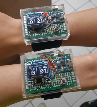
The 3rd International Conference on Eco Engineering Development                                                IOP Publishing
IOP Conf. Series: Earth and Environmental Science 426 (2020) 012161                        doi:10.1088/1755-1315/426/1/012161

Wearable Device for Restaurant Operational that Employs
People with Hearing Impairment

                     Rudy Susanto*, W Oktavianus, W Prayogo, Santoso Budijono, Rico Wijaya
                     Computer Engineering Department, Faculty of Engineering, Bina Nusantara University,
                     Jakarta, Indonesia 11480.

                     *Coresponding Author: rudy.susanto@binus.ac.id

                     Abstract. Speed in serving consumers is one of the top priorities in restaurants. To provide fast
                     and precise service, it needed a device that is able to help the operational system at restaurant.
                     This research focus on creating a device that can help operational system at restaurant that can
                     be controlled using the smartphone. The device is designed to combine several components that
                     were merged into a wearable device. The result is wearable devices that can last 7 hours 34
                     minutes with 2 hours charging time, average operating distance 35.3 m, and 5% error glitch.

                     Keywords: Restaurant, Android, Wearable Device, Firebase.

1. Introduction
One of the benefits that can be felt from technological developments can be applied to help human
jobs [1, 3]. Developments in the food sector are also felt. The real evidence that can be seen is the
increasingly rapid competition carried out by many restaurants both in the variety of food, service,
room decoration, and so on [2]. A good restaurant must have a good service factor as well as fast and
correct food serving desired by the customer. In situations where the restaurant is crowded with
customers, waiters are required to work quickly to serve customer orders and deliver orders. By being
demanded to work fast the servants sometimes lose their concentration of work which consequently
results in mistakes [1, 4].
   The most common mistakes occur due to misunderstanding in receiving information. In the
delivery of information such as calling a waiter, delivering food, delivering food bills, using sound
media [4]. Using sound media to convey commands or information is less effective especially if the
conditions of the restaurant are very noisy and crowded. One way to overcome this problem is the
need for a tool that can send or receive commands without going through voice media [5].
   The main objective is to study the distance of the wearable device connected to the router, the
conveniences of the device for the users, and power needed by wearable devices during operations.
The expected benefit is a system which can be felt for companies, especially restaurants, are that
restaurant operations are easier in taking orders to deliver food, clean tables, and other tasks. And extra
provide benefits for people with hearing impairment to be able to work efficiently.
   Scope of this study includes: Three prototypes to conduct the experiment, each device uses a 0.96"
graphic OLED LCD, a Wi-Fi network through a router as an access point, a total of 10 barcodes
available to represent costumers table. The control system uses Wemos D1 mini ESP-8266 and using
the Android operating system at least version 2.1 for the smartphone.

              Content from this work may be used under the terms of the Creative Commons Attribution 3.0 licence. Any further distribution
              of this work must maintain attribution to the author(s) and the title of the work, journal citation and DOI.
Published under licence by IOP Publishing Ltd                          1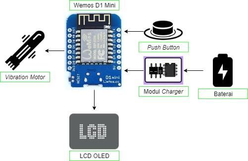
The 3rd International Conference on Eco Engineering Development                                       IOP Publishing
IOP Conf. Series: Earth and Environmental Science 426 (2020) 012161               doi:10.1088/1755-1315/426/1/012161

2. Methodology
2.1 Hardware
Figure 1 shows the outline of the system to be designed in this design where each device is connected
to each other and has their respective functions. The designed device can be attached on hand. The
OLED LCD device, Wemos D1 Mini ESP-8266 and vibration motor, were made into a single device.
A small lithium polymer battery is use for the power source. The smartphone functions as a wearable
device control by communicating through wireless networks to the Wemos D1 Mini ESP-8266.
Smartphones are divided into two, namely smartphones for cashiers and smartphones for at the desk.
In the system there is also a database as storing data variables to be used in the communication process
between smartphones.
                                    Battery
                                    Battery      Charger
                                                 Charger Module
                                                         Module

                                                WEMOS
                                                WEMOS D1
                                                       D1 Mini
                                                          Mini
                                   OLED
                                   OLED LCD
                                        LCD                        Vibration
                                                                   Vibration Motor
                                                                             Motor
                                                  ESP-8266
                                                  ESP-8266

                                   Smartphone
                                   Smartphone    Mikrotik
                                                 Mikrotik Router
                                                          Router       Database
                                                                       Database
                                    (Table)
                                     (Table)

                                                  Smartphone
                                                  Smartphone
                                                   (Chasier)
                                                    (Chasier)

                                       Figure 1. System Block Diagram

   The process that occurs includes identification and confirmation. The identification process that
occurs is the Wemos D1 Mini ESP-8266 identifies the commands given by the smartphone. While the
confirmation process occurs when the smartphone sends command data to the wearable device and
then when the wearable device has undergone the command, the wearable device will send the
confirmation data back to the smartphone. Confirmation data contains information that the command
has been executed or has been completed.

                            Figure 2. Hardware Diagram of Wearable Devices.

   Figure 2 shows the Wemos D1 Mini ESP-8266 is the control centre of the system. Wemos D1 Mini
ESP-8266 is connected to an OLED LCD, vibration motor, charger module, push button and battery.
OLED LCD functions to display the command display for users. Vibration motor serves to provide
notification to the user in the form of vibration. The charger module functions to charge the battery,

                                                        2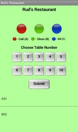
The 3rd International Conference on Eco Engineering Development                                         IOP Publishing
IOP Conf. Series: Earth and Environmental Science 426 (2020) 012161                 doi:10.1088/1755-1315/426/1/012161

push button as a button to confirm the user against the commands given. The battery functions as a
power source for all devices.

2.2 Software
          Start                                     Start                                                  G

                                                                                                 Data is sent to device
         system                                    system                                                1/2/3
       initializing                              initializing

                                                                                                   Waiting status is
                                                                                                     displayed

     Display Screen                            Display Screen

                                                                                                   Device button is       N
     Barcode Scan                               Action button                                         pressed?
                                               input + number
                                                 and submit
                                                                                                               Y

        Action
      button input                                                                               Progress is displayed
      and submit

                                            Order saved and get
                                            update from Firebase
                                                                                                   Device button is       N
   Save and get update
                          Firebase                                                                    pressed?
     from Firebase

                                              Display order on                                                 Y
                                                 menu list
    Display order on
       menu list                                                                                 Delete command in
                                                                                                   menu and add in
                                                                                                 history of command
                                                      G

                                                                                                         End

                                             Command in menu            N
                                                is pressed?

                                                            Y

                                             Notification display
                                              Delete or Cancel

                                                  Delete is         N       Cancel is    N
                                                  pressed?                  pressed?

                                                                                Y
                                                          Y

                                             Erase command on
                                                    menu

                                     Figure 3. Main flow diagram of software

                                                                3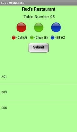
The 3rd International Conference on Eco Engineering Development                           IOP Publishing
IOP Conf. Series: Earth and Environmental Science 426 (2020) 012161   doi:10.1088/1755-1315/426/1/012161

Figure 3 shows the flow diagram of the whole system on Android which is divided into two parts,
namely the flow diagram on the table application and the flow diagram on the cashier application. In
the table application, when it is first started there is a system initialization that is connecting to the
database. Then it displays a menu display on the screen that requires the user to scan the barcode so
that the table application knows which table the number is in use. When the command is sent, the table
application sends data to the database to be processed by the cashier application where the cashier
application is the communication control centre. Then the command is displayed on the application
table menu and continuously updating data from the database.
   In the cashier application, the initial process is to initialize the system to connect to the database
and check connections between wearable devices, then display the menu on the screen. If the
command and number buttons are pressed, then the submit button is pressed, the cashier application
sends data to the database and displays on the list menu after that send the command to the wearable
device. The table application displays the "waiting" status and continuously checks whether the button
on the wearable device is pressed. If pressed the status changes to "progress". If the button on the
wearable device is pressed again, the command will disappear and be stored in the history list. The
process of the desk application and the cashier application exchange data across the database so that
the commands sent by the desk application will be seen in the cashier application and vice versa the
commands sent by the cashier application will be seen also in the table application.

3. Results
3.1 Hardware and software results.
The results of the design are applications contained in the Android operating system and wearable
devices. On wearable devices in Figure 4there is a 0.96" OLED LCD to display commands to the user,
there is a push button to receive commands, there is a battery as a power source for the device and
there is a switch to activate or deactivate the device.

                                       Figure 4. Wearable Device

    The application on android is used to make a booking system made into two applications, namely
for the cashier and table. The application contained in the cashier is used to send orders that are
already listed on the list. While the application contained in the table or table is used only to register
orders that will later be received by the database which is then forwarded to the smartphone contained
at the cashier.

                                                     4
The 3rd International Conference on Eco Engineering Development IOP Publishing
IOP Conf. Series: Earth and Environmental Science 426 (2020) 012161 doi:10.1088/1755-1315/426/1/012161
(a) (b)
Figure 5. (a) User applications.(b). Cashier applications.
3.2 Maximum Distance
Testing is done by bringing each wearable device away from the beacon router. Ping tests are carried
out continuously by carrying the wearable device farther until the ping test results show a timeout
indicating that the connection between the router and the wearable device has been lost.
Table 1.Farthest distance wearable device until signal is dropped
Wearable Device Farthest Distance (m)
Device 1 35,8 m
Device 2 34,7 m
Device 3 35,4 m
The usage of the data from the wearable device is 813 bytes on standby mode, 1075 byte when
receiving a message and 1104 when receiving erase command.
3.3. Battery test
The battery capacity used is 1500 mAh. The wearable device must continue to run for at least 8
hours in correlation for the restaurants working hour. Two experiments were carried out to see the
condition on wearable devices. The first in Table 2 is to testdurationof a wearable device stays in
standby and the second in shown in Table 3is totestduration of a wearable device lasts when being
used continuously by sending commands along with vibrations every 10 seconds. All data is measured
from the max condition of the battery 4.11 V to 3.22 V.
Table 2.Wearable device usage in standby mode
Wearable devicenumber- Duration (hours)
1 7:55
2 7:40
3 7:40
Table 3.Wearable device usage in busy mode
Wearable devicenumber- Duration (hours)
1 6:33
2 6:30
3 6:15
5The 3rd International Conference on Eco Engineering Development IOP Publishing
IOP Conf. Series: Earth and Environmental Science 426 (2020) 012161 doi:10.1088/1755-1315/426/1/012161
Table 4 and Table 5shows the charging time and condition of the device. Experiments is carried out
with the condition of the battery has run out, while charging the wearable device is turned off and
using a mobile charger with a voltage of 5 V and a current of 2 A.
Table 4.Charging duration.
Wearable device number- Duration (hours)
1 2:00
2 2:09
3 2:07
Table 5. Charging condition
Duration Wearable Device number -
(minutes) 1 2 3
30 60 % 63 % 60 %
60 85 % 89 % 87 %
90 92 % 96 % 93 %
120 100 % 99 % 99 %
3.4. Glitches and Error
The test aims is to see how many errors are generated. The condition in question is the condition of
the device working optimally to the point where an error occurs or beyond the normal use limit of the
tool. These errors occur due to limitations of the system on the device. In wearable devices, the
condition is set by pressing and holding the push button continuously on the wearable device. Whereas
on Android Application, conditions is set by continuously sending commands to wearable devices
together (less than 1 second), the results is shown in Table 6.
Table 6. System response in error conditions
Device Error occurred Anomaly cause Solution
Wearable Glitch in LCD display if The LCD still keeps the Buffer cleared and
Device the button is continuously previous buffer. refresh rate increased to
pressed every second.
Push button bounce The firmware responds to Bounce is set by using
effect slow and some loop done software and additional
inefficiently hardware.
Android Command is not sent State difference in software A process is added to
when device is on when offline and online accommodate the offline
standby mode mode.
Multiple devices not The proses of registering in A 20 ms delay is given
detected when the device Firebase database can only for command form the
is doing almost the exact detect the last device device.
time registered
Conclusion
This study addressed the capabilities wearable device to help an operational system at restaurant that
can be controlled using the smartphone. The device is designed to combine several components that
were merged into a wearable device. The result is a wearable device that can last 7 hours 34 minutes
with 2 hours charging time, with average operating distance 35.3 m and 5% error glitch.
6The 3rd International Conference on Eco Engineering Development IOP Publishing
IOP Conf. Series: Earth and Environmental Science 426 (2020) 012161 doi:10.1088/1755-1315/426/1/012161
References
[1] Kristinawati Y, Akbar S R and Maulana R 2018 Implementation of Battery Capacity Monitoring
Module on Embedded Devices (J. Information Technology and Computer Science
Development 2) (Bandung : Indonesia Institute of Science) p 3210–3219 2018 2548 964X
[2] Mihardja E A and Adeline A 2013The Role of Wireless Table Calling System Technology on
Service Quality at Sushi Tei Central Park Restaurant (Jakarta: Bina Nusantara University)
2013 2 00818 HM
[3] Ngafifi M 2014 Advances in Technology and Patterns of Human Life in Socio-Cultural
Perspective (J. Educational Development: Foundation and Application 2) (Yogjakarta:
Postgraduate of Yogyakarta State University) p 33–47 2014 2502 1648
[4] Susila T, Winata T, Rakhman S N 2006 Designing Food Ordering Equipment (J. TESLA:
Electrical Engineering Journal8) (Jakarta: Tarumanagara University) p 61–68 2006 2665 7967
[5] Wijaya D, Primananda R, Data M 2018Analysis of Power Consumption and Performance for
Uploading and Downloading Data on Ad-Hoc Networks and Infrastructure Networks on
Raspberry Pi’(J. Information Technology and Computer Science Development 2 )(Bandung :
Brawijaya University)p 2504–2512 2017 2548 964X
7You can also read


