ACCURACY IN WIFI ACCESS POINT POSITION ESTIMATION USING ROUND TRIP TIME
←
→
Page content transcription
If your browser does not render page correctly, please read the page content below
sensors
Article
Accuracy in WiFi Access Point Position Estimation Using
Round Trip Time
Miquel Garcia-Fernandez * , Isaac Hoyas-Ester, Alex Lopez-Cruces                               , Malgorzata Siutkowska
and Xavier Banqué-Casanovas

                                          Rokubun S.L., 08018 Barcelona, Spain; isaac.hoyas.ester@rokubun.cat (I.H.-E.); alex.lopez@rokubun.cat (A.L.-C.);
                                          malgorzata.siutkowska@rokubun.cat (M.S.); xavier.banque@rokubun.cat (X.B.-C.)
                                          * Correspondence: miquel.garcia@rokubun.cat

                                          Abstract: WiFi Round Trip Time (RTT) unlocks meter level accuracies in user terminal positions
                                          where no other navigation systems, such as Global Navigation Satellite Systems (GNSS), are able to
                                          (e.g., indoors). However, little has been done so far to obtain a scalable and automated system that
                                          computes the position of the WiFi Access Points (WAP) using RTT and that is able to estimate, in
                                          addition to the position, the hardware biases that offset the WiFi ranging measurements. These biases
                                          have a direct impact on the ultimate position accuracy of the terminals. This work proposes a method
                                          in which the computation of the WiFi Access Points positions and hardware biases (i.e., products)
                                          can be estimated based on the ranges and position fixes provided by user terminals (i.e., inverse
                                          positioning) and details how this can be improved if raw GNSS measurements (pseudoranges and
                                          carrier phase) are also available in the terminal. The data setup used to obtain a performance
                                          assessment was configured in a benign scenario (open sky with no obstructions) in order to obtain an
                                          upper boundary on the positioning error that can be achieved with the proposed method. Under

                                   these conditions, accuracies better than 1.5 m were achieved for the WAP position and hardware bias.
Citation: Garcia-Fernandez, M.;           The proposed method is suitable to be implemented in an automated manner, without having to
Hoyas-Ester, I.; Lopez-Cruces, A.;        rely on dedicated campaigns to survey 802.11mc-compliant WAPs. This paper offers a technique to
Siutkowska, M.; Banqué-Casanovas,         automatically estimate both mild-indoor WAP products (where terminals have both Wi-Fi RTT and
X. Accuracy in WiFi Access Point          GNSS coverage) and deep-indoor WAP (with no GNSS coverage where the terminals obtain their
Position Estimation Using Round Trip      position exclusively from previously estimated mild-indoor WAPs).
Time. Sensors 2021, 21, 3828. https://
doi.org/10.3390/s21113828                 Keywords: WiFi; Round Trip Time; fine time measurements; Access Points; GNSS; navigation

Academic Editor: Maorong Ge

Received: 23 April 2021
                                          1. Introduction
Accepted: 27 May 2021
Published: 1 June 2021
                                                 The WIFI 802.11mc protocol ([1]) allows a device to measure the distance to a WiFi
                                          Access Point (WAP) in a bi-directional communication process. The user terminal initiates
Publisher’s Note: MDPI stays neutral
                                          this process, and the WAP responds to the query, which eventually results in an estimation
with regard to jurisdictional claims in
                                          of the distance through the Round Trip Time (RTT, details on the protocol can be found
published maps and institutional affil-   in, e.g., [2]). As of today, the amount of devices supporting this protocol is scarce, limited
iations.                                  to few router brands that are able to both announce support for the 802.11mc protocol and
                                          respond to RTT queries (examples are Compulab WILD and Google WiFi routers as well as
                                          other mesh network routers). On the initiator side, to the authors’ best knowledge, only
                                          Google Pixel and other high end smartphones support this feature ([3]), albeit other open
Copyright: © 2021 by the authors.
                                          platforms based on Intel chipsets have also been proposed (see, e.g., [4,5]).
Licensee MDPI, Basel, Switzerland.
                                                 This technology promises a breakthrough in indoor navigation, particularly in a
This article is an open access article
                                          smart city environment where smartphones are ubiquitous and applications based on this
distributed under the terms and           technology can enhance Location-Based Service applications ([6]). While the benefit of
conditions of the Creative Commons        this technique will be mostly evidenced in indoor environments, using RTT-based WiFi
Attribution (CC BY) license (https://     positioning could potentially be used to assist GNSS in areas with a lack of visibility
creativecommons.org/licenses/by/          (i.e., urban canyons) or to reduce the time-to-first-fix by providing a meter-level a priori
4.0/).                                    position.

Sensors 2021, 21, 3828. https://doi.org/10.3390/s21113828                                                      https://www.mdpi.com/journal/sensors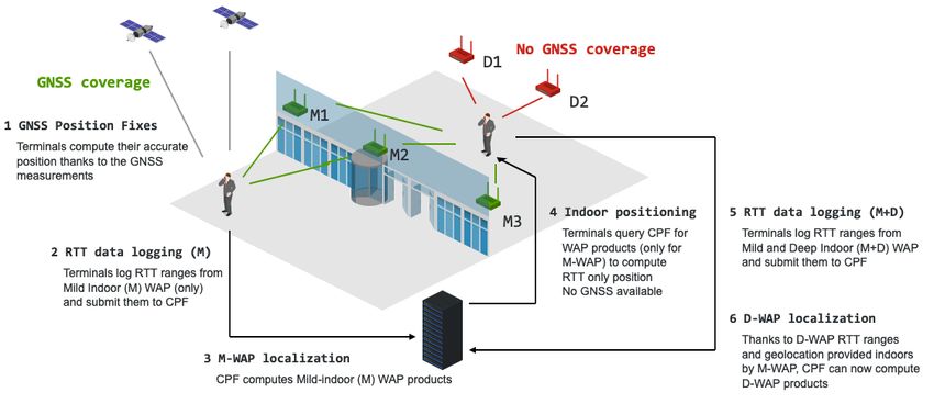
Sensors 2021, 21, 3828                                                                                                  2 of 13

                               In addition, RTT-based positioning could serve as an alternate position provider in
                         GNSS denied or compromised (i.e., spoofed) environments. Indeed, the measurement
                         accuracy of the RTT ranges is on the order of tens of decimeters (see, for instance, [7]), which
                         certainly allows meter-level accuracy (as shown in [8–12]). However, besides environmental
                         error sources, such as multipath, RTT ranges are usually offset due to biases introduced by
                         the WAP hardware ([13]).
                               Despite this potential breakthrough, there is a clear limitation of the 802.11mc protocol
                         due to its bi-directional nature, as opposed to other navigation systems, such as Global
                         Navigation Satellite Systems (GNSS), that are unidirectional (i.e., user terminals only
                         receive and do not transmit information to the satellites). The fact that an initiator has to
                         start a dedicated communication with the WAP limits the scalability of systems based on
                         WiFi RTT. Some works propose methodologies to synchronize a set of WAPs so that the
                         complete system is more GNSS-like (i.e., unidirectional, see [2,14]), which would enable a
                         fully scalable solution.
                               Thus far, most works on WiFi RTT deal with the positioning of the user terminal using
                         WiFi RTT or a hybridized strategy with ranging GNSS ([15]); however, WAP positioning
                         remains a topic to be fully investigated. An accurate estimation of the WAP position will
                         impact the final accuracy in the user terminal, and thus lowering the WAP positioning error
                         is critical. In previous works, WAP positions were usually obtained by survey campaigns
                         using geodetic grade GNSS receivers (see, for instance, [16]).
                               However, this solution is not practical for operational systems, and thus an auto-
                         mated methodology should be developed. This work intends to provide a solution
                         based on the fact that raw GNSS measurements have been available in Android de-
                         vices since 2016 ([17]) which unlocks the possibility of having sub-metric accuracy in
                         smartphones ([18–20]). Therefore, geotagging the RTT measurements with a more accurate
                         user terminal position has, in turn, the potential to better locate the position of WAPs.
                               In the following paper, we intend to provide a methodology to estimate the WAP
                         position and hardware bias as well as to improve these estimates by means of exploiting
                         the better accuracy offered by processing the raw GNSS measurements. The paper starts
                         with a description of the data processing model and is followed by the Results section,
                         describing the data campaign executed to test the model and the quality assessment of the
                         estimation of WAP position and hardware bias as well as its impact in the terminal location.
                         The paper is concluded with the Discussion section, which contains our conclusions of
                         the work.

                         2. Data Processing Model
                              In a similar way as in other range-based navigation systems, such as GNSS (see, for
                         instance, Section 6.1.1 of [21]), the basic measurement to compute a receiver (rx) position
                         based on the known coordinates of a set of transmitters (tx) is the range between the
                         receiver and these transmitters. This geometric distance (ρ) can be computed as:
                                                     q
                                                ρ = ( xtx − xrx )2 + (ytx − yrx )2 + (ztx − zrx )2                (1)
                         which can be linearized using a first order Taylor expansion, which requires an a priori
                         knowledge of the element to be geolocated. Albeit this linearization can yield to biases
                         in the estimated state, specially if the a priori is too coarse, it is needed when estimation
                         strategies based on Kalman filtering are used [22]. The linearization would yield the
                         following expression:
                                                  xtx − xrx,0        ytx − yrx,0        ztx − zrx,0
                                             ρ'               · ∆x +             · ∆y +             · ∆z                   (2)
                                                      ρ0                 ρ0                 ρ0
                         where ρ0 is the distance between the WiFi Access Points (WAP) (i.e., transmitters) and the
                         a priori position of the user terminal to geolocate (receivers): ~rrx,0 = ( xrx,0 , yrx,0 , zrx,0 ). A
                         possible method to compute the approximate a priori position of the user terminal could
                         be by means of the Bancroft method (see, for instance, Appendix D of [23]).
Sensors 2021, 21, 3828 3 of 13
In the ideal case (i.e., no biases and no measurement errors), if the user terminal
measures the RTT from at least three WAPs, the position delta relative to the a priori
(∆~r = (∆x, ∆y, ∆z)) can be solved by a simple Root Mean Square solution. While WiFi
RTT ranging is a two-way communication system (as opposed to GNSS), and therefore no
receiver clock has to be estimated, previous works showed that the RTT measurements
were affected by an offset or bias ([13]). Therefore, the WiFi RTT range measurement (ρ RTT )
is better modeled using the following expression:
ρ RTT = p x · ∆ x + py · ∆y + pz · ∆z + bhw + ε σ (3)
where p is the partial of the component, defined as:
tx − rx,0
p = , (4)
ρ0
where bhw is the hardware bias (offset) introduced by the Access Point, as pointed out
in [13] and is expressed in meters. Finally, ε σ is the modeled thermal (Gaussian) noise of
the measurement (with standard deviation σ). The user terminal position can be, therefore,
estimated by solving the following linear system of N equations (one equation per each
WAP for which there is a RTT measurement):
− p1x − p1y − p1z
1
ρ RTT − ρ1RTT,c
∆x
ρ2RTT − ρ2RTT,c − p 2 − p 2 − p 2
x y z
· ∆y
= (5)
.. ..
. .
∆z
N
ρ RTT N
− ρ RTT,c − p xN − pyN − pzN
where the prefit residuals for the i − th WAP (ρiRTT - ρiRTT,c ) are the measured RTT range
minus the computed RTT range (using the model proposed in Equation (3)), and pi is the
partial for the component and for the i-th WAP.
As can be seen, to compute the user terminal, not only the WAP position but also the
bias (bhw ) is needed. Not adding the bias into the navigation equations will increase the
error of the estimated positions.
To solve the inverse positioning problem and obtain both the WAP location and bias
(instead of the user terminal position), the linear system shown in Equation (5) needs to be
slightly reformulated as follows:
ρ RTT,1 − ρ RTT,c,1
p x,1 py,1 pz,1 1 ∆xtx
ρ RTT,2 − ρ RTT,c,2 p x,2 py,2 pz,2 1
∆ytx
= · (6)
.. .. ∆ztx
. .
ρ RTT,M − ρ RTT,c,M p x,N py,M pz,M 1 bhw
Instead of N equations in this case we have M measurements collected by the smart-
phone. These M measurements can be taken from a single terminal at different geographical
locations within the WAP area coverage or by simultaneous terminals under the WAP cov-
erage at different locations and epochs. The combination of measurements from different
terminals, locations and epochs can be done because the WAP hardware bias (bhw ) is rela-
tively stable over time (as noticed by the authors as well as in [13]); therefore, measurements
over different epochs can be processed in the same batch. This is slightly different than
other navigation systems, such as GNSS, where the receiver clock biases depend over time,
and thus measurements over different epochs have to be processed in different batches.
Clearly, the data processing model will not only need the RTT measurements as the
basic observable but also the position at which this measurement was taken (i.e., the user
terminal location). In smartphones, when using terminals such as Google Pixel 4, the RTT
measurements can be geotagged with the position fixes provided by the Android Location
Service. However, it is important to note that the error in the terminal position will directly
impact the accuracy with which the WAP position can be estimated.Sensors 2021, 21, 3828 4 of 13
To improve the terminal location, other positioning algorithms can be used as shown
later in this paper. Examples of such techniques include Precise Point Positioning (PPP,
which uses code and carrier GNSS measurements as well as precise orbits and clocks)
and Post-Processing Kinematics (PPK, which uses differential techniques with nearby
GNSS reference stations). These techniques can be also applied in Android smartphones
due to the fact that, since 2016, the Android API has granted access to the GNSS raw
measurements to the developers (see [17,24]).
3. Data Campaign and Setup
In order to test the data processing model presented above and assess its best possible
performance (upper boundary on the positioning error), a data campaign was carried out to
collect RTT measurements in a controlled and benign setup (open sky and no obstructions).
The hardware equipment used in this campaign corresponds to five WiFi Access routers
from CompuLab (WILD), which were RTT compliant, and two Google Pixel 4 smartphones.
The five WiFi routers (red) were placed in a concentric circle of 10 m (red circle) centered at
the Central Point shown in Figure 1 as a white circle.
Figure 1. The five WiFi routers were placed around a circle of 10 m, centered at the Central Point
(CP). The positions of the routers and CP where surveyed using a Septentrio AsteRx GNSS receiver
and a Post Processing Kinematic (PPK) strategy.
The positions of each Access Point were surveyed using a geodetic-grade GNSS
receiver (Septentrio AsteRx with a PolaNt antenna) using a Post Processing Kinematic
(PPK) strategy that allows achieving centimetric accuracy in the position estimates (see, for
instance, [25,26]). These positions will be the truth reference to which the estimated Access
Point locations will be compared to. The positions as well as the network identifiers (SSID)
are collated in Table 1.Sensors 2021, 21, 3828 5 of 13
Table 1. Reference position (ETRS89 reference frame) of the Wifi Access Points, surveyed with a
Septentrio AsteRx GNSS receiver.
SSID Longitude [deg] Latitude [deg] Height [m]
CP 2.1640443 41.8091309 931.137
WILD_0001 2.1639939 41.8090443 930.374
WILD_0002 2.1640822 41.8090430 930.518
WILD_0003 2.1641564 41.8091737 930.797
WILD_0004 2.1640039 41.8092222 930.690
WILD_0005 2.1639418 41.8091072 930.463
In addition to surveying the location of the Access Points, the Central point location
was also measured using a geodetic-grade GNSS receiver. This allowed us to obtain an
accurate distance between the Access Points and this central point, which is collated in
Table 2
Table 2. Geometric distances between the setup Central Point (CP) and each of the routers considered
in the data campaign.
SSID Distance to CP [meters]
WILD_0001 10.5
WILD_0002 10.3
WILD_0003 10.3
WILD_0004 10.7
WILD_0005 8.9
Hardware Bias Estimation
As already pointed out in the data processing section and in [13], WiFi RTT mea-
surements might have an offset that, if not modeled, will directly impact the positioning
accuracy of the user terminals. Therefore, a service providing the WiFi Access Point (WAP)
position should also provide an estimation of the WAPs bhw so that end-users can obtain
the best possible WiFi-based positioning. This service should jointly estimate both the
position as well as the hardware bias bhw of the WAP at the same time, through the solution
of the linear system of equations represented in Equation (6).
This section attempts to assess the typical size of this hardware bias bhw in a controlled
environment using an independent method that is different from the proposed inverse
positioning technique—the average difference between the observed RTT ranges and the
true measured ranges (the geometrical distance between the terminal and the Access
Point). This will be used later when comparing the results obtained with the inverse
positioning technique.
To achieve this, the data set described in the previous section was used: the two
smartphones were placed at the central point (CP). The relative distances were estimated
with centimetric accuracy as the difference between the surveyed positions of the CP and
the WAP location. Both the CP and WAP locations were estimated using a Post-Processed
Kinematics (PPK) strategy (with centimeter-level accuracy, see, for instance, [26]). These
relative distances are collated in Table 2.
In order to estimate the biases, the prefit residuals of the WiFi RTT measurements
collected by the two smartphones at the CP were obtained (i.e., the observed RTT range
measurements minus the true distance to the router). In the ideal case where no hbw is
present, the resulting prefit residuals would be 0. In reality, a bias was evidenced, as shown
in Figure 2. The prefit residuals were clearly biased by an amount that is on the meter level
(ca. −5 m), consistent with magnitudes observed in other works ([13]). A simple averaging
of the prefit residuals for each router yielded the biases, which are collated in Table 3.
An important result that can be obtained from this analysis is the standard deviation
of these prefit residuals, which provides an indication of the the thermal noise for the RTTSensors 2021, 21, 3828 6 of 13
measurements. As it can be seen, this was comprised between 20 and 70 cm and compatible
with the measurement error reported by Android devices (by the field DistanceStdDevMm,
see [27]) and already reported in previous works ([28]). No evident pattern was observed
between the hardware bias and the environment of the smartphone. However, the hardware
bias did seem to depend on the frequency at which the RTT measurements were collected
(i.e., 2.4 or 5 GHz), according to further data samples collected after this test campaign.
Figure 2. Prefit residuals of the RTT measurements (observed by the smartphones placed at CP
minus the true distance).
Table 3. The estimated hardware biases (in meters) using the true positions of the Access Points
and smartphone positions (surveyed with a Septentrio AsteRx GNSS recever). Both the estimated
hardware bias as well as the precision of this estimation is shown in the table for each router.
SSID bhw [meters] σ pre f it [meters]
WILD_0001 −5.124 0.22
WILD_0002 −4.933 0.67
WILD_0003 −4.609 0.67
WILD_0004 −4.880 0.59
WILD_0005 −5.018 0.49
4. Results
4.1. Wifi Access Point Positioning
This section contains the results of the WAP positioning estimate (as well as the
hardware biases) using the processing model described above. RTT measurements from
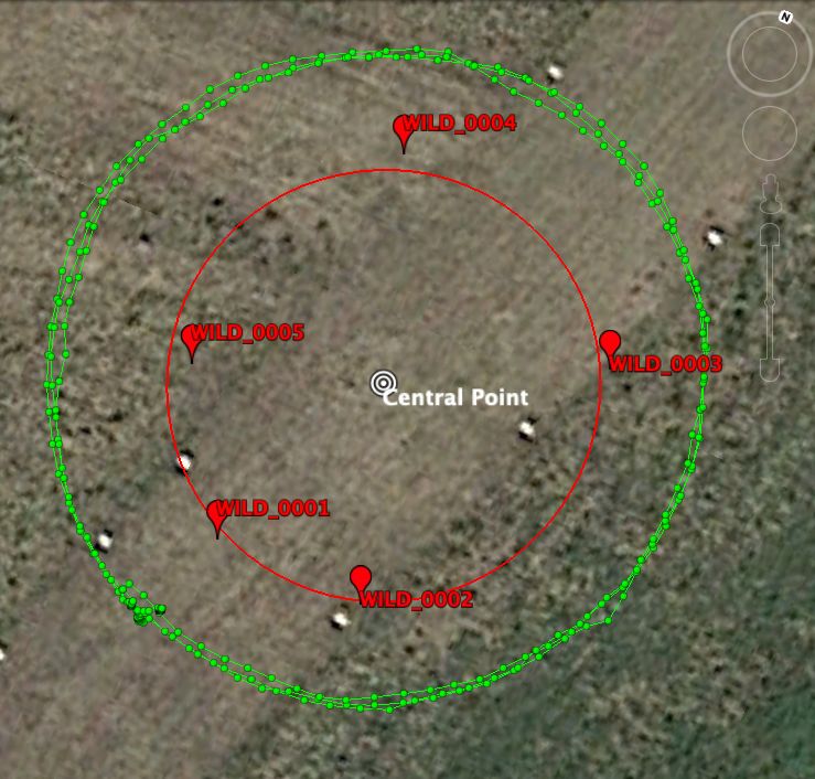
the two Google Pixel 4 smartphones were collected with a tailored app while walking
around various circles outside the setup, as shown by the green line in Figure 3.Sensors 2021, 21, 3828 7 of 13
As can be seen, the environment was open sky without obstructions. Therefore this
can be considered as a benign scenario and a measure of the best possible accuracy that can
be obtained using WiFi RTT measurements collected with a smartphone. A more realistic
scenario will likely yield worse results due to environmental errors, such as multipath
(nearby walls and obstructions), signal blockage (user holding the smartphone), and higher
dynamics (turns and accelerations, . . .).
Figure 3. The smartphones followed various circle of a ca. 15-meter radius that contained the whole
setup shown in Figure 1.
As mentioned before, in order to perform the inverse positioning and estimate the
positions of the WAP, the RTT measurements need to have an associated position. For
this work, two positions were considered: the Android position, where the position was
obtained from the user terminal itself (Android Location Service), and the Jason Position,
where the position was estimated using PPK computed with the GNSS measurements from
the user terminal.
Due to the feature that allows extracting the GNSS raw measurements from smart-
phones, in particular, the carrier phase (e.g., [29]), accessing sub-meter accuracy on those
devices is possible by applying differential techniques, such as PPK (see, for instance, [30]).
The app developed as a data grabber of RTT measurements for this work contains marks
for synchronisation with the GPS time scale. This feature is needed to retag those measure-
ments with a sub-meter accuracy. To do this, the GNSS data gathered by the smartphones
was uploaded to Rokubun’s Jason cloud GNSS service ([31]) to obtain a PPK solution. The
resulting position estimates (timetagged with the GPS time scale) were used to interpolate
the position at the epochs where the RTT measurements were taken.
To evaluate the accuracy of the proposed inverse positioning strategy to compute the
WAP positions, the obtained positions were compared against the reference positions
surveyed with the Septentrio AsteRx receiver (see Table 1). These basic metrics were
considered as performance indicators:
• Position errors—essentially the horizontal and vertical errors. These errors can be
computed using a tangential reference frame (East/North/Up): as is known, givenSensors 2021, 21, 3828 8 of 13
a reference position and a 3D error vector, the East and North components are the
projection of the error vector in the East and North directions, respectively, while the
Up component is the projection of the error vector in the vertical direction. In the
tangential reference frame, the vertical error (∆vertical ) is directly the Up component,
while the horizontal deviation (∆horizontal ) is defined in Equation (7).
• Hardware bias errors—computed as deviation to the reference values described in the
previous section (see Table 3).
q
∆horizontal = ∆2east + ∆2north (7)
The results for these metrics are collated in Tables 4 and 5 for the two strategies to tag
the RTT measurements described above (using Android location and retagging with Jason,
respectively). The most noticeable difference was due to the improvement in the horizontal
error when using the Jason service (to retag the RTT measurements with the PPK position
estimates): when using Android location, errors larger than 2.5 m were obtained, while they
were clearly reduced to less than 1.5 with the Jason location.
The vertical errors were, in general, larger than the horizontal ones, but this is because
of the geometry distribution of the setup. As is known from other navigation systems,
such as GNSS, the Dilution-Of-Precision (DOP) causes an error amplification when the
geometry of the receivers and transmitters is not diverse (i.e., all observations aligned, see,
for instance, Section 6.1.2 of [21]).
Due to the fact that, in the proposed setup, all transmitters and receivers were in the
same plane, the vertical geometry was worse than the horizontal geometry. Better vertical
accuracy could have been obtained if RTT measurements above the routers were available.
The DOP is usually quantified using the geometry matrix of the observations, and the
lower the value is, the less error amplification. In the proposed setup, horizontal DOP of
around 3 were obtained, while the vertical DOP was about 50, indicating a high difference
in the geometric diversity between these two components.
Table 4. Results with RTT measurements tagged with the Android Position. Horizontal and vertical
position deviations relative to the reference WAP positions and computed WAP hardware bias.
SSID ∆horizontal [meters] ∆vertical [meters] bhw [meters]
WILD_0001 2.6 3.4 −4.2
WILD_0002 2.8 −2.8 −3.4
WILD_0003 1.1 −0.9 −2.5
WILD_0004 0.9 −3.3 −2.5
WILD_0005 2.7 8.0 −3.6
Table 5. Results with RTT measurements tagged with the Jason Position. Horizontal and vertical
position deviations relative to the reference WAP positions and computed WAP hardware bias.
SSID ∆horizontal [meters] ∆vertical [meters] bhw [meters]
WILD_0001 1.3 0.7 −4.3
WILD_0002 2.0 2.6 −3.5
WILD_0003 0.4 2.5 −2.7
WILD_0004 0.9 5.6 −2.2
WILD_0005 1.5 −1.2 −3.8
Concerning the hardware bias, in general, the resulting hardware biases were esti-
mated within 1 to 1.5 m relative to the values provided in the previous section, and no
substantial differences between both strategies were detected. However, these differences
are within the same magnitude of the thermal noise error of the RTT measurements (see
the last column of Table 3 and Figure 2).Sensors 2021, 21, 3828 9 of 13
4.2. Impact on the Terminal Accuracy
The ultimate goal of having the positions and hardware biases of the WAPs is to
provide the best possible accuracy to user terminals using the RTT, particularly in areas
with limited or no GNSS coverage (for instance in deep indoor environments). This section
outlines the expected accuracy that can be achieved using the service based on the method-
ology proposed in this paper, also known as the WAP Location Service (WALS). This section
is not intended to provide a full report on using WiFi RTT for user terminal navigation,
as this has been widely covered in previous references (see, for instance, [9,10,15] and the
references therein). Rather, we intend to gauge the impact of using different sets of WAP
positions and biases in the position of the user terminals.
For this test, the two smartphones were placed at the Central Point. They collected
Wifi RTT measurements for ca. 1 min and then were processed using Rokubun’s navigation
filter using two sets of WAP coordinates and biases: (a) the ones obtained by surveying the
position with the Septentrio GNSS receiver (True position) and (b) the ones obtained with
the proposed service (WALS position).
The panels in Figure 4 show the East/North/Up deviation relative to the reference
position of the Central Point. The figure summarizes the results for the two smartphones
used in the test, using the true positions and hardware biases (upper panels) and using the
ones delivered by WALS instead (lower panels). As expected, the differences (especially in
the vertical dimension) increased due to the fact that the WAP position and hardware biases
delivered by WALS had estimation errors in the meter level (as reported in the previous
section). However, the horizontal error was within 2 m. The vertical component showed
the larger deviation due to the worse DOP in the vertical dimension, which amplifies any
measurement error of the RTT ranges.
Figure 4. Result for the two Google Pixel smartphones (user terminal) in static positioning using the true WAP position and
biases (above) and WALS WAP position biases (bottom).
A more qualitative test can be performed in a dynamic test where the smartphones
are moved around a circle with a constant radius of 15 m (similar to the green circle in
Figure 3). The results for the horizontal dimension (easting and northing) are shown in
Figure 5 for the two sets of WAP positions. As expected, the track at 15 m was betterSensors 2021, 21, 3828 10 of 13
followed when more accurate WAP positions were provided (green track, using the true
WAP positions) than when the positions provided by the proposed methodology (WALS)
were used. However, the errors were still within the 2-m level.
Figure 5. The results of the WiFi positioning in a dynamic environment using WAP positions
obtained from a true reference or from the proposed methodology (WALS).
5. Discussion
WiFi Round Trip Time measurements, enabled with the 802.11mc protocol, unlock
the possibility of navigating with meter-level accuracy where there is no access to other
navigation systems (e.g., GNSS does not work indoors). However, one key point to be able
to perform this is to have accurate positions as well as the hardware (or system) biases of
the WiFi Access Points (WAP). To the authors’ best knowledge, little attention has been
paid so far to this problem, and previous works typically offered ad-hoc approaches, where
the Access Points were surveyed with dedicated campaigns. This approach is not scalable,
particularly considering the vast amount of potential RTT-capable WAPs that might appear
in the future, and an automated system might be required to compute both the position as
well as the biases of those WAPs.
We proposed an inverse positioning methodology by which user terminals provide
the RTT ranges geotagged with the terminal position in order to estimate the position of the
Access Points. Moreover, this estimation was improved using raw GNSS measurements
(pseudoranges and carrier-phases) provided by the user-terminal in addition to the RTT
ranges. In this case, differential GNSS techniques, such as PPK, can be used to improve the
positions at which the RTT measurements were obtained causing a reduction in the error
of the WAP position and hardware bias.
This process can be easily automated using an Application Programming Interface
(API) of services, such as Rokubun’s Jason, which accepts GNSS data collected by smart-
phones and delivers the PPK position. Accuracies better than 1.5 m were achieved in the
horizontal dimension, but the error in the vertical dimension increased due to a worse
dilution-of-precision (DOP). In addition, The WAP biases can also be estimated with an
accuracy of 1 to 1.5 m. Once the WAP positions and hardware biases are computed, they areSensors 2021, 21, 3828 11 of 13
stored in a database and served, via the API, to other users that need this data to compute
their own positions in the GNSS denied environment (i.e., indoors).
It is unlikely that terminals sending data to the server to compute WAP products use
these products to compute their own positions. Instead, terminals under the coverage of
WAPs that are near windows in buildings (i.e., mild-indoors) will compute their locations
using GNSS and then submit RTT measurements with these GNSS-based geotags.
The server will apply the inverse positioning technique to compute these mild-indoor
WAP products with the accuracy level shown in this paper. At a later stage, other terminals
could use these mild-indoor WAP products to compute their positions in locations without
GNSS visibility (for instance well within the building, deep-indoors) and, potentially,
geotag RTT measurements of other nearby WAP that are deep-indoors. These geotagged
RTT measurements could be then sent to the server to compute the products of these
deep-indoors WAPs, albeit with a potential decrease in accuracy.
A whole system level description of an architecure using the inverse positioning
technique is shown in Figure 6. Terminals under coverage of WAPs that are near windows
in buildings (i.e., mild-indoors) will compute its location using GNSS only (i.e., Wi-Fi RTT
ranges may not be needed for this purpose at this stage). This user’s RTT measurements
would be geotagged with this GNSS fix and then submit them to the server. The server
will apply the inverse positioning technique to compute these mild-indoor WAP products
with the accuracy level shown in the previous section. At a later stage, other terminals
located indoors, with no GNSS visibility, could use these mild-indoor WAP products to
compute its position. Eventually, the Wi-Fi only position fixes could be used to geotag RTT
measurements of other nearby WAP that are deep-indoors. Note that these deep-indoor
RTT measurements have not been used to compute the terminal position because, at this
stage, the deep-indoor WAP products have not been yet computed and are not available to
the user. Finally, these geotagged RTT measurements could be then sent to the server to
compute the products of these deep-indoors WAPs.
Figure 6. Process flow of the typical use case for the inverse positioning technique proposed in
this paper.
The essential requirements in terms of hardware in order for this technique to be
applicable is that terminals and WAP support Wi-Fi 802.11mc. A list of devices supporting
this protocol is listed in [3]. Regarding the Access Points, besides the one listed in this
reference, modern commercial mesh systems such as Netgear Orb, Amazon Eero or Linksys
Velop do support also this protocol.
In the future, additional lines for future work include an analysis of the hardware
bias stability for the same device in subsequent power cycles. Moreover, more realistic
studies involving indoor environments should be considered to assess the real impact of
obstructions and also to assess the extent to which WAP with no outdoor visibility (such
as the ones placed in deep indoor environments) can be estimated exclusively with otherSensors 2021, 21, 3828 12 of 13
WAP for which their positions and hardware biases could be successfully estimated with
the proposed technique (i.e., WAP near windows or mild indoors).
6. Patents
As a result of the methodology described in this work, the following patent is cur-
rently under evaluation in the European Patent Office (EPO): GEOLOCATING WIRELESS
ACCESS POINTS (Application number EP20194450.1 filed on 3 September 2020).
Author Contributions: Conceptualization, research, methodology and writing, M.G.-F.; GNSS data
analysis, I.H.-E.; software, A.L.-C. and M.S.; funding acquisition and contributions in the data cam-
paign execution, X.B.-C. All authors have read and agreed to the published version of the manuscript.
Funding: This research was funded by the European Space Agency through the Technology Trans-
fer Proof of Concept, under contract 4000131075/20/NL/MH/kdj and the Article Processing
Charges (APC) of this manuscript were funded by the European GNSS Ageny (GSA) under grant
GSA/GRANT/04/2019/BANSHEE.
Informed Consent Statement: Not applicable.
Conflicts of Interest: The authors declare no conflict of interest.
References
1. Wi-Fi Alliance. Wi-Fi CERTIFIED Location Orientation; Technical report; WiFi Alliance: Austin, TX, USA, 2020.
2. Banin, L.; Bar-Shalom, O.; Dvorecki, N.; Amizur, Y. Scalable Wi-Fi client self-positioning using cooperative FTM-sensors. IEEE
Trans. Instrum. Meas. 2018, 68, 3686–3698. [CrossRef]
3. Android. Android Developers, Devices that support WiFi-RTT. 2020. Available online: https://developer.android.com/guide/
topics/connectivity/wifi-rtt#supported-devices (accessed on 25 May 2020)
4. Ibrahim, M.; Liu, H.; Jawahar, M.; Nguyen, V.; Gruteser, M.; Howard, R.; Yu, B.; Bai, F. Verification: Accuracy evaluation of WiFi
fine time measurements on an open platform. In Proceedings of the 24th Annual International Conference on Mobile Computing
and Networking, New Delhi, India, 29 October 2018; pp. 417–427.
5. Zhu, Y. Enable 802.11mc FTM on Intel 8260. 2019. Available online: https://github.com/HappyZ/iw_intel8260_localization/
wiki/Enable-802.11mc-FTM-on-Intel-8260 (accessed on 21 December 2020).
6. Minetto, A.; Dovis, F.; Vesco, A.; Garcia-Fernandez, M.; López-Cruces, À.; Trigo, J.L.; Molina, M.; Pérez-Conesa, A.; Gáñez-
Fernández, J.; Seco-Granados, G.; et al. A Testbed for GNSS-Based Positioning and Navigation Technologies in Smart Cities: The
HANSEL Project. Smart Cities 2020, 3, 1219–1241. [CrossRef]
7. Ogawa, M.; Choi, H. Measurement accuracy of Wi-Fi FTM on actual devices. IEICE Commun. Express 2020, 9, 567–572. [CrossRef]
8. Banin, L.; Bar-Shalom, O.; Dvorecki, N.; Amizur, Y. High-Accuracy Indoor Geolocation Using Collaborative Time of Arrival; Technical
report; Intel: Santa Clara, CA, USA, 2019.
9. Horn, B.K. Doubling the Accuracy of Indoor Positioning: Frequency Diversity. Sensors 2020, 20, 1489. [CrossRef] [PubMed]
10. van Diggelen, F.; Want, R.; Wang, W. How to Achieve 1-meter Accuracy in Android. GPS World. 2018. Available online:
https://www.gpsworld.com/how-to-achieve-1-meter-accuracy-in-android/ (accessed on 21 December 2020).
11. Malkos, S.; Hazlett, A. Enhanced WiFi Ranging with Round Trip Time (RTT) Measurements. In Proceedings of the 27th
International Technical Meeting of the Satellite Division of The Institute of Navigation (ION GNSS+ 2014), Tampa, FL, USA, 8–12
September 2014; pp. 108–116.
12. Xu, S.; Chen, R.; Yu, Y.; Guo, G.; Huang, L. Locating smartphones indoors using built-in sensors and Wi-Fi ranging with an
enhanced particle filter. IEEE Access 2019, 7, 95140–95153. [CrossRef]
13. Bai, Y.B.; Kealy, A.; Hoden, L. Evaluation and correction of smartphone-based fine time range measurements. Int. J. Image Data
Fusion 2020, 2020, 1–17. [CrossRef]
14. Martin-Escalona, I.; Zola, E. Passive Round-Trip-Time Positioning in Dense IEEE 802.11 Networks. Electronics 2020, 9, 1193.
[CrossRef]
15. Fernandez, D.; Barcelo-Arroyo, F.; Martin-Escalona, I.; Ciurana, M.; Jofre, M.; Gutierrez, E. Fusion of WLAN and GNSS
observables for positioning in urban areas: The position ambiguity. In Proceedings of the 2011 IEEE Symposium on Computers
and Communications (ISCC), Kerkyra, Greece, 28 June–1 July 2011; pp. 748–751.
16. Bai, Y.B.; Kealy, A.; Retscher, G.; Hoden, L. A Comparative Evaluation of Wi-Fi RTT and GPS Based Positioning. In Proceedings
of the International Global Navigation Satellite Systems IGNSS 2020 Conference, Sydney, Australia, 5–7 February 2020; pp. 5–7.
17. Malkos, S. Google to Provide Raw GNSS Measurements. 2016. Available online: https://www.gpsworld.com/google-to-
provide-raw-gnss-measurements/ (accessed on 22 December 2020).
18. Humphreys, T.E.; Murrian, M.; van Diggelen, F.; Podshivalov, S.; Pesyna, K.M. On the feasibility of cm-accurate positioning via a
smartphone’s antenna and GNSS chip. In Proceedings of the 2016 IEEE/ION Position, Location and Navigation Symposium
(PLANS), Savannah, GA, USA, 11–14 April 2016; pp. 232–242.Sensors 2021, 21, 3828 13 of 13
19. Agency, E.G. Using GNSS Raw Measurements on Android Devices, White Paper; Technical report; GSA: Washington, DC, USA, 2018.
20. Fu, G.M.; Khider, M.; van Diggelen, F. Android Raw GNSS Measurement Datasets for Precise Positioning. In Proceedings of the
33rd International Technical Meeting of the Satellite Division of The Institute of Navigation (ION GNSS+ 2020), Online, 21–25
September 2020; pp. 1925–1937.
21. Misra, P.; Enge, P. Global Positioning System: Signals, Measurements and Performance, 2nd ed.; Ganga-Jamuna Press: New York, NY,
USA, 2006; Volume 206.
22. Gao, S.; Hu, G.; Zhong, Y. Windowing and random weighting-based adaptive unscented Kalman filter. Int. J. Adapt. Control
Signal Process. 2015, 29, 201–223. [CrossRef]
23. Sanz-Subirana, J.; Juan-Zornoza, J.M.; Hernández-Pajares, M. Gnss Data Processing, Volume I: Fundamentals and Algorithms;
European Space Agency Communications: Noordwijk, The Netherlands, 2013.
24. Cameron, A. Google Opens up GNSS Pseudoranges. GPS World. 2016. Available online: https://www.gpsworld.com/google-
opens-up-gnss-pseudoranges/ (accessed on 21 December 2020).
25. Remondi, B.W. Performing centimeter-level surveys in seconds with GPS carrier phase: Initial results. Navigation 1985, 32, 386–400.
[CrossRef]
26. Colombo, O.L.; Sutter, A.W.; Evans, A.G. Evaluation of precise, kinematic GPS point positioning. In Proceedings of the ION
GNSS 17th International Technical Meeting of the Satellite Division, Long Beach, CA, USA, 21–24 September 2004; pp. 1423–1430.
27. Android. Android Developers, Wifi RTT Ranging Results. 2020. Available online: https://developer.android.com/reference/
android/net/wifi/rtt/RangingResult (accessed on 22 December 2020).
28. Garcia-Fernandez, M.; Lopez-Cruces, A. Geolocating with WiFi RTT Measurements. 2020. Available online: https://www.
rokubun.cat/geolocating-with-wifi-rtt-measurements/ (accessed on 22 December 2020).
29. Garcia-Fernandez, M. GNSS Carrier Phase from Nexus 9. 2017. Available online: https://www.rokubun.cat/gnss-carrier-phase-
nexus-9// (accessed on 22 December 2020).
30. Banville, S.; van Diggelen, F. Precision GNSS for Everyone. GPS World 2016, 27, 43–48.
31. Rokubun. Rokubun Jason GNSS Cloud Service. 2020. Available online: https://jason.rokubun.cat (accessed on 22
December 2020).You can also read