ALUMINIUM DOOR INSTALLATION GUIDE - Crystal Direct
←
→
Page content transcription
If your browser does not render page correctly, please read the page content below

ALUMINIUM DOOR
INSTALLATION
GUIDE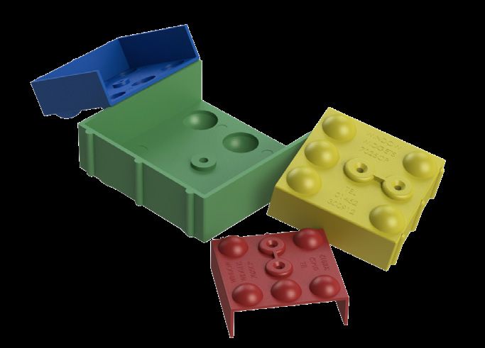
EAN Numbers
Bi-Folding doors
5060456211004
5060456211011
5060456211028
5060456211035
5060456211042
5060456211059
5060456210014
5060456210007
5060456210038
5060456210021
5060456210052
5060456210045
5060456210069
5060456210076

French doors
5036581078775
5036581078782
5036581078799
Welcome to your new door
Thank you for choosing a new energy
efficient door from GoodHome. Your
new door has been manufactured to
the highest quality standards and is
1
guaranteed for 15 years.
Your door will arrive unglazed and it is
important that you stack the door in
a vertical position - prevent your door
being damaged by stacking on flexible
material between surfaces, such as
wooden blocks.
Your door is delivered fully fabricated
and should retain the protective film Protective corner blocks
until all building works are complete.
2
Your delivery contains:-
1. Door - the door will have corner
blocks attached. These are there
for protection - remove these prior
to installation - see No 1.
2. Handle - already attached to the
door. This is fitted with handle
mesh for protection - see No 2. Door handle
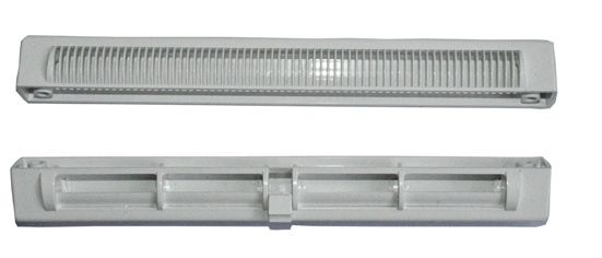
3. Trickle vents - these are taped to
the door - see No 3. 3
4. Glazing packers, cill and cill end
caps - these are in a plastic bag -
see No 4.
Trickle vents
Prior to installation please ensure that
your new door has been checked for
imperfections or any damage. 4
Please report any issues within 48 hours
of delivery.
Glazing packers, cill
and cill end caps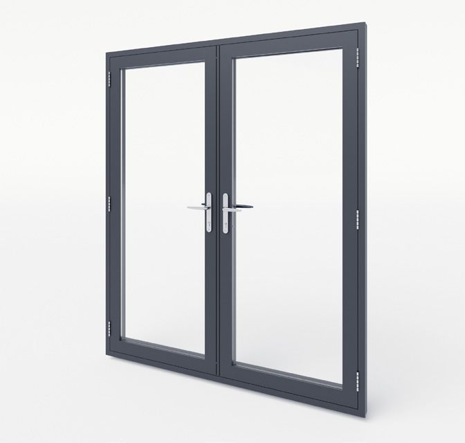
Fitting the new frame
 1                                         2

                                           Frame with a cill
           Please read through
                                           If you are fitting a frame with a cill, first
          all of this instruction
          guide before starting.           decide if you are going to run the cill
                                           around the brickwork or cut it flush to
                                           the finished width of the hole.

                                           Whichever way you decide to do it, cut
Remove the old frame                       the cill to size with a fine toothed saw
Before removing your existing frame        to fit tightly back to the inside edge
double check that your new frame fits      where the old frame sat. You may have
into the existing aperture.                to remove the tongue of the internal
                                           window board first.
Once the old frame has been removed,
brush away any loose debris or cement,     Affixing a cill
leaving a clean opening ready to receive
                                           Once the cill has been cut to size, apply
the new frame.
                                           a line of sealant along the cill upstand
                                           and across the frame platform at each
                                           end. Screw them together, through the
                                           bottom frame section along the centre
                                           line and into the cill.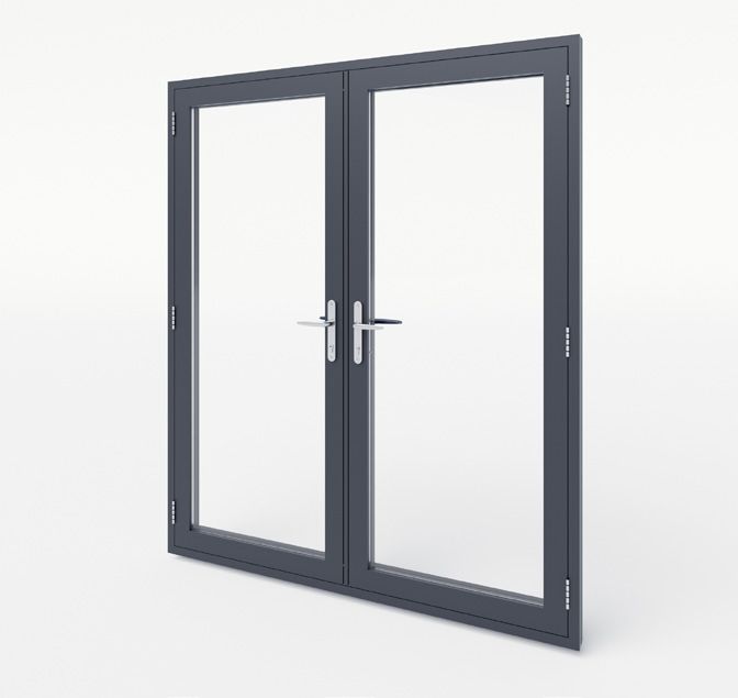
3

Insert new frame
Offer the frame into the opening and
using a spirit level, ensure the frame is
level, vertical and not twisted before
wedging into position.

Centralise it and insert packers
underneath to level it and maintain the
5mm expansion gap.
4                                            5.   Fix the side of the frame to the wall.
                                                       To avoid distortion to the frame and
                                                       maintain the 5mm expansion gap
                                                       use packers (do not overtighten the
                                                       fixings).

                                                  6.   On wider frames ensure you fix
                                                       the top and bottom of the frames.
                                                       Ensure that the top and bottom
                                                       fixings are sealed with silicone to
                                                       prevent moisture absorbing into the
                                                       brickwork.

                                                  7.   When finished ensure you clean any
                                                       brick dust from your new frame.

                                                  8.   For optimum thermal and acoustic
Affix new frame                                        performance, it is critical that the
                                                       gap between the door product
1.       Remove any packaging from the                 and the aperture is fully insulated
         new frame and screw the cill onto             using a suitable expanding foam or
         the bottom of the frame. Make                 expanding foam tape.
         sure you select a screw that doesn’t
         penetrate the inner skin of the
         frame.

2.       Seal the ends of the cill and frame
         to prevent moisture tracking along
         the cills into the brickwork.

3.       Position the frame into the prepared
         aperture. Centralise it and use
         packers to ensure that it is level and
         to maintain a 5mm expansion gap.

4.       Once the frame is level drill fixing
         holes into the frame sides. These
         should be drilled 150mm from
         the top and bottom corners and
         600mm inbetween (a minium of 2
         fixings per side).
Glazing
     1                                                2

How to glaze the new door                           Toe and heeling
Starting with one of the longest beads              Opening doors (sash) are heavy, and
first, remove the glazing beads by                  although the dead weight is supported
pushing a sharp chisel or a rigid paint             on the hinge side when it is opened,
scraper between the bead and the frame              there is nothing on the lock side to
joint at approximately the centre point.            support the weight, and without the
A sharp tap on the butt of the tool                 procedure of toe and heeling the door
should allow the bead to be freed. It is            will drop on the handle side. To prevent
most important to refit the beads in the            a sash dropping, the glass has to be
same positions as they were removed,                braced diagonally corner to corner (see
they may vary in length slightly, due to            diagram) by the insertion of plastic
the manufacturing process.                          packers slipped in the gap between the
                                                    glass or panel and frame.
1.       Place into position the glass packers
         approximately 100mm in from each
         corner (intermediate packers should
                                                     How to toe and heel
         be used if the double glazed unit is        The door or sash on the lock side
         wider than 1200mm).                         should be raised to the desired
                                                     height and squared up with the door
2.       Place the double glazed unit
                                                     frame. On the hinge side place the
         into the frame ensuring correct
                                                     packers at the bottom corner, whilst
         positioning on the glass packers.
                                                     on the lock side, the packers go at
3.       Starting on one of the shortest             the top (opposite) corner - place a
         lengths, fit 3 of the beads moving          dab of silicone under the packers on
         around the frame using a rubber             the door sides to stop the packers
         mallet, finally fitting the last bead by    dropping. lt is advisable to use a
         bending it into position.                   glazing shovel when lifting the glass or
                                                     panel. The packers should be placed
N.B. It is always best to leave one of the
                                                     approximately 150mm from the edge
longer beads until last as a long bead
                                                     of the frame.
will locate and bend more easily.
3
Door hinge Lock and Keep adjustment
• On the main lock, ensure that the
latch is catching and the handle
throw allows the hooks to move
into position and the key turns
the cylinder. On the shoot-bolt
locks, ensure the handle can be
turned freely and the bolts engage
smoothly with the frame.
• Check the perimeter gaskets on the
sashes are providing an even seal
and constant and even gasket line.
• In case the sash-frame or sash-sash
clearance is causing interference
or is deemed to be too small, the
plastic packing strips under each
hinge can be removed to increase
the closing gaps.
• Compression on the lock can be
adjusted by rotating the rollers in
the required position.
• Further adjustment is available via
keep positions.
• It is recommend to undertake any
adjustments after the final glazing.Bi-fold door survey and installation
1 2
General Preparing the structural opening
BS 8213-4:2007 Code of Practice Check that the opening is the correct size
for the Survey and Installation of for the new frame (N.B.: For replacement
Windows and External Doorsets gives work this should be done prior to
recommendations for the surveying and removal). Check that any DPC’s are
installation of non-load bearing windows sound and not “bridged” by any render
and external doorsets, to be installed or plaster. Check for the practicality of
vertically (within 15°) into the external fixings to the lintels. The base of the
face of buildings. opening must be constructed of suitable
structural material, e.g.: brick, block, stone,
It gives guidance on the good practices timber etc.
for successful surveying and installation.
All aspects of this document should 3
be followed with particular attention
given to the product’s suitability for its Installing the Frame
location and the presence of any dead
loads. Wherever possible the survey Fixing the Cill :-The method shown
should identify any necessary variations requires the cill to be fitted to the base
to the standard installation techniques of the opening making sure that the base
such as lug fixing or direct fixing. is clean of loose debris and the DPC is
Fixing methods are determined by the Intact. The method shows lug fixing over
construction of the structural opening cavity closer. The cill is levelled by using
and the method of drainage. If you are appropriate shims placed under each
at all unsure then please contact your fixing centre. Then fix with the appropriate
supplier. Any finished floor level should frame fixings 200mm from each end
clear the bottom of a sash (gasket) by at at a maximum of 600mm centres (In
least 5mm in closed and open position, accordance with BS 8213-4:2007). Apply
to avoid any interference cause by silicone as shown between frame and cill.
installation tolerances and unevenness. Lift the frame onto the cill and adjust the
frame in the opening to be square, plumb
Personal protective equipment should and straight. Use temporary wedges to set
be worn at all times during installation the frame square in the opening. Wedge
and on building sites. In order to protect shims between frame and brickwork to
surroundings from dust and debris, it is achieve final positioning of frame. Use
recommended to use dustsheet where diagonal measurement across opposite
possible. corners of the outer frame to check.Installing the frame cont...
With frame in place, use suitable fixing
method to fix frame jambs and frame
head to the brickwork.
Fixings should be 200mm from top
and bottom corners and no more than
600mm centres in between. Use fixing
lugs for cill fixing and outer-frame
(jambs and head) fixing.
Check the frame is in square by Make sure that in line with each fixing a
measuring the diagonals from opposite shim is placed to avoid any distortion of
corners. the frame during tightening the screws.
Finally fix the frame to cill using 45-
Ensure that head is fixed level with no
50mm self-tapping PVC screws, by
bow in either plane.
pre-drilling aluminium frame section.
Countersink if appropriate and/or place
gasket back in to position.
Fixing cillFinally check that the door, runs, folds, Check the perimeter gaskets on the
closes and locks properly and is secure. sashes are providing an even seal and
The bottom track should be cleared of constant and even gasket line.
any debris and mortar prior to operating In case the sash-frame or sash-sash
the door using a builders’ vacuum or clearance is causing interference or
other suitable cleaning equipment. This is deemed to be too small, the plastic
is to ensure that no damage is caused to packing strips under each hinge can be
the wheels and track. removed to increase the closing gaps.
Compression on the lock can be
On the main lock, ensure that the latch adjusted by rotating the rollers in the
is catching and the handle throw allows required position.
the hooks to move in to position and the
key turns the cylinder. On the shoot-bolt Further adjustment is available via keep
locks, ensure the handle can be turned positions.
freely and the bolts engage smoothly
with the frame. It is recommend to undertake any
adjustments after the final glazing.
Lock and keep adjustment4 Glazing Bridge packers are clipped into position top corners where shown. Make sure as shown. Additional glazing packers the final fix packers do not work against should be used to properly toe and the toe & heel packers. To ensure safe heeling all sashes of the door. When toe working, glass suckers should be used. and heel, ensure each sash is not pushed PVC beads are inserted by using a soft out of alignment. Use toe and heeling tipped mallet and aluminium beads are to align sashes correctly so that they inserted pushing in the wedge gaskets are running freely, provide even gasket provided. compression, clearances and locking. Packers for final fix are to be placed into
Finishing
  2                                          Clean the external surfaces to remove
                                             the dirt and grit.

                                             Apply a strip of masking tape to the
Perimeter sealing
                                             frame perimeter. Apply a smooth bead
The purpose of perimeter sealants is         of silicone sealant between the frame
to repel water and prevent air leakage       and brick work. Before the sealant sets,
in the face of differential movement         remove the masking tape to create a
between the aperture and the doorset.        neat finish. It is important to remember
It is important to prevent water entering    to seal below the external cill.
between the frame and the structure
from the outside, but also to seal air       Trims and profiles come in lots of
gaps on the inside. This is to prevent       different shapes and sizes to cover
moist air reaching over the insulation       sealant and fixings. They’ll give you a
and creating condensation.                   neat, professional finish, inside and out.

                                             You can cover wider gaps around the
Suitable sealants exhibit and retain         outside of the door with a PVCu scotia
flexibility and adhesion over this period.   trim. Do this by sealing the frame behind
The movement class for the sealant           the trim with frame sealant. You can
will depend on the substrate material,       then stick the trim in place with more
the frame material and the dimensions        frame sealant.
of the joint between the frame and the
opening.

It is advisable to clean down the frame
before sealing the perimeter.

The gap between the outer frame and
structure must be sealed using a suitable
external grade sealant. 5-6mm gaps can
be filled with sealant alone, however
larger gaps may require the use of foam         You have finished!
backing strips.
                                                Once you have installed your new
                                                door, open and close it to ensure
In some cases a small cover trim will be
                                                that it is working correctly.
required to produce a neat finish.

If access allows, the gap below the cill
should be pointed with sealant. If this
is not possible, ensure that the cill has
been set on a suitable silicone or mortar
bed.
Top tips looking after your doors
Our top tips to keep your doors in the Locking
best condition, we recommend... To operate the lock, insert the key into
• That you carry out routine the cylinder. Rotate the handle upwards
maintenance on your doors at and turn the key for one complete
least twice a year. In areas of high evolution to activate the deadbolt, which
exposure, you may want to do this locks the whole mechanism. Release the
more frequently. handle.
• All parts of your new doors that Unlocking
are exposed when closed, should Insert the key into the cylinder and
be washed down with warm soapy disengage the deadbolt by turning
water using a soft cloth, then dried one complete revolution. Depress the
thoroughly. handle and open the door. Where a split
• Any parts that are exposed when spindle is fitted in addition, after you
the window is open, should simply have depressed the handle, turn the key
be wiped clean, removing any a further quarter revolution to release
grime, dirt, insect remains or old the latch.
lubricant.
• You avoid any cleaning agents that
have ammonia in them or that are
abrasive, particularly on handles
and other metal fittings.
• Special attention is paid to keep
drainage channels clear and free
from any blockages.
• That any moving parts and fixings
are treated as follows:
• The application of light oil, to
keep the locking mechanism in
good working order.
• A suitable acid and resin free
grease should be used on sliding
bars, gears and face plates.
• Maintenance of friction stays is
important and we recommend
that you follow the guidelines for
lubrication and adjustment.Guarantee conditions
We take special care to select high result of improper use, faulty installation
quality materials and use manufacturing or assembly, neglect, accident, misuse,
techniques that allow us to create or modification of the product. Unless
products incorporating design and stated otherwise by applicable law, this
durability. This GoodHome product (has guarantee will not cover, in any case,
a manufacturer’s guarantee of 15 years ancillary costs (shipping, movement,
against manufacturing defects, from the costs of uninstalling and reinstalling,
date of purchase (if bought in store) labour etc), or direct and indirect
or date of delivery (if bought online), damage.
at no additional cost for normal (non-
If the product is defective, we will, within
professional or commercial) household
a reasonable time, repair it or replace it.
use.
Rights under this guarantee are
To make a claim under this guarantee,
enforceable in the country in which
you must present your proof of
you purchased this product. Guarantee
purchase (such as a sales receipt,
related queries should be addressed to
purchase invoice or other evidence
the store you purchased this product
admissible under applicable law), please
from.
keep your proof of purchase in a safe
place. For this guarantee to apply, the The guarantee is in addition to and does
product you purchased must be new, it not affect your statutory rights.
will not apply to second hand or display
Manufacturer:
products. Unless stated otherwise by
applicable law, any replacement product
Kingfisher International Products Limited
issued under this guarantee will only be
3 Sheldon Square, London W26PX
guaranteed until expiry of the original
United Kingdom
period guarantee period.
This guarantee covers product failures Kingfisher International Products B.V.
and malfunctions provided the product Rapenburgerstraat 175E
was used for the purpose for which it 1011 VM Amsterdam, The Netherlands
is intended and subject to installation,
cleaning, care and maintenance in Distributor:
accordance with the information
contained in these terms and conditions, B&Q plc. Chandlers Ford. Hants
in the user manual and standard SO53 3LE, United Kingdom
practice, provided that standard www.diy.com
practice does not conflict with the user
manual. SFD Limited, Trade House, Mead
Avenue, Yeovil BA22 8RT,
This guarantee does not cover defects
United Kingdom
and damage caused by normal wear and
www.screwfix.com
tear or damage that could be the(EN) DECLARATION OF PERFORMANCE
No’ DOP_C79782_5036581078775_1
EN - Unique identification code of the Product type : EAN 5036581078775
EN - By extension, this declaration of performance also applies to any EAN product codes detailed in Appendix 1
• Insert Product name –Aluminium Double Leaf Doors
• Insert Product model – Stellar
EN - Intended use: Aluminium Double Leaf Doors intended to be used in domestic and commercial locations
(Name, registered trade name or registered trademark and contact address of the manufacturer as required under Article 11(5))
Kingfisher International Products B.V., Rapenburgerstraat 175E, 1011 VM Amsterdam, The Netherlands
(System or systems of assessment and verification of constancy of performance of the construction product as set out in CPR, Annex V:)
EN - System(s) of assessment and verification of constancy of performance: System 3
(Relevant EN standards (hEN) relevant harmonised standards used, or references to the specifications in relation to which performance is
declared)
EN - Harmonized standard: EN 14351-1:2006+A2:2016
(Notified Body lab name, number)
EN - Notified body/ies: 1806, report number CU20099-2
EN - Declared performance/s:
EN - Essential Characteristics EN - Performance EN - Standard / EAD FR - Norme / DEE
FR - Caractéristiques Essentielles FR - Performance
PL - Norma / EDO RO – Standard / DEE
PL - Zasadnicze Charakterystyki PL - Właściwości użytkowe
DE - Norm / EBD TR - Standart / EAD
RO - Caracteristicile Esențiale RO - Performanta
DE - Wesentlichen Merkmale DE - Leistung ES - Norma / DEE PT - Norma / DAE
TR - Temel Karakteristikler TR - Performans
ES - Características Esenciales ES - Prestación
PT - Características Essenciais PT - Desempenho
Watertightness NPD BS EN 1027
Dangerous substances None BS EN 14351-1:2006
Resistance to wind load NPD BS EN 12211
Impact resistance NPD BS EN 13049
Load-bearing capacity of safety devices None BS EN 948
Ability to release NPD BS EN 179 & BS EN 1125
Acoustic performance NPD BS EN ISO 140-3
Thermal transmittance 1.5 W/m²K EN ISO 10077-1 & 10077-2 or 12567-1 &
prEN 12567-2
Radiation properties NPD EN 410
Air permeability NPD EN 1026
EN - The performance of the product identified above is in conformity with the set of declared performance/s. This declaration of performance is
issued, in accordance with Regulation (EU) No 305/2011, under the sole responsibility of the manufacturer identified above
Signed for and on behalf of
Kingfisher International Products B.V.,
Rapenburgerstraat 175E,
1011 VM Amsterdam,
The Netherlands
EU DOP CPR MULTI LINGUAL_20191003v1
Eric Capotummino - Group Quality Director [18/03/2020]
Appendix 1
List of EAN’s:
5036581078775
5036581078782
5036581078799You can also read