ALUMINIUM INSTALLATION INSTRUCTIONS - Balustrade and Pool Fences - Sentrel Balustrade & Pool Fencing
←
→
Page content transcription
If your browser does not render page correctly, please read the page content below
INSTALLATION INSTRUCTIONS
______________________________________________________________________________________

ALUMINIUM
Balustrade and Pool Fences

Sentrel Australia Pty Ltd
sentrel.com.au

1300 658 330
NOTE!
These instructions will guide you through the process for mounting Sentrel Aluminium Balustrade
and Pool Fence panels.
We advise that you read through these instructions completely to ensure that you understand the
process and achieve the best results. NOTE: Please take care handling the powder coat finish
and pay special attention to the procedure for using post adhesive.

Sentrel will take no responsibility for problems arising from installations that are not
in accordance with our instructions.

FITTING SENTREL BRACKETS TO EXISTING POSTS

  Brackets must be fixed to the posts with screws
suitable for the post material (not supplied).
  Be sure to position brackets so that the small
hole in the short face is to the underside. This
hole is for fixing the panels into the brackets. Only
the top rail needs to be fixed into the top brackets
and sufficient Tek screws are supplied.
  Installations with handrail have truncated
brackets that must be fixed at the top of the posts       Small hole must be
with the open face upwards.                               on the underside

For Balustrades
 Installations with timber or aluminum handrail require the brackets to be fixed so that the gap
under the bottom rail is no less than 60mm and no greater than 125mm. Failure to do this will
mean a non-compliant installation. We recommend a gap of approximately 80mm.
  Installations with no handrail require the brackets to be fixed so that the gap under the bottom
rail is no less than 75mm and no greater than 125mm. Failure to do this will mean a non-
compliant installation. We recommend a gap of approximately 80mm.

For Pool Fencing
 Installations with timber or aluminum handrail require the brackets to be fixed so that the gap
under the bottom rail is no less than 60mm and no greater than 100mm. Failure to do this will
mean a non-compliant installation. We recommend a gap of approximately 80mm.
  Installations with no handrail require the brackets to be fixed so that the gap under the bottom
rail is no less than 75mm and no greater than 100mm. Failure to do this will mean a non-
compliant installation. We recommend a gap of approximately 80mm.

.
                                                   2
PANELS WITH HANDRAIL PANELS WITH NO HANDRAIL
60 - 125mm 75 - 125mm
Positioning brackets on existing posts — Balustrade
NOTE: Finished panel height will vary from approx. 1000 - 1060mm according to gap under bottom rail
PANELS WITH HANDRAIL PANELS WITH NO HANDRAIL
60 - 100mm 75 - 100mm
Positioning brackets on existing posts — Pool fence
NOTE: Finished panel height will vary from approx. 1200 - 1260mm according to gap under bottom rail
3FITTING SENTREL POSTS
Sentrel posts are adhered with an anaerobic adhesive (Chemtools 8680 Retaining
Compound—supplied) to special spigots. The spigots must be positioned strictly in
accordance with the layout drawing.
Fixing Posts to a Concrete Slab
Mark a centreline along the run where post spigots are to be placed.
Mark the spigot placement along the centreline as indicated in the layout drawing.
Drill 18mm holes, 90mm deep into the slab. NOTE: Ensure that the holes are drilled a
minimum of 100mm from the edge of the slab.
Fix the 16mm threaded rod (supplied) into the holes with an appropriate anchoring
adhesive, eg. Ramset Chemset 101 (not supplied) in accordance with the product directions.
NOTE: Ensure that all holes are cleaned out thoroughly after drilling, and remove ALL
excess adhesive extruding from threaded rod/ hole after gluing. Failure to do this will result in
a loose/unstable spigot mounting that will not comply with building standards.
Trim threaded rods to 50mm above Finished Floor Level (FFL).
Mark centerlines 100mm
Fix spigots with nut minimum from edge of slab
and washer supplied
Drill 18mm hole, 90mm deep. Fix
rod and trim to 50mm above FFL
Place spigots over rods, and secure with washers and nuts to torque of 90 Nm. Ensure that
all spigots are positioned square to the job and sitting firmly on the slab.
4Fixing Posts to a Timber Deck
Ensure that the spigots are laid out in the correct position in
accordance with the layout drawing.
It may be possible to fix the spigots to a joist
below with a 16mm coach screw or similar (not Fixing holes
supplied). Otherwise, use the four fixing holes in
the spigot and screw to deck with a minimum of
10 gauge galvanized screws (not supplied).
Decking boards must be made structurally suitable for mounting the spigots. It will be
necessary to reinforce them from the underside by gluing blocks across several decking boards.
Failure to do so may lead to lateral movement of the post.
FIXING POSTS TO SPIGOTS
Ensure that you have everything required to fit and plumb the post before beginning (i.e.
mallet, timber block & level).
With a string line or otherwise, establish levels at each spigot. Note the variation, and choose
the lowest point as a reference. If required, trim the BOTTOM of the posts accordingly to bring
top of posts level. NOTE: This is a fine tune only. No more than 15mm can be removed from the
bottom of any one post. If level differences are greater than this amount, other means will be
required to compensate for the differences.
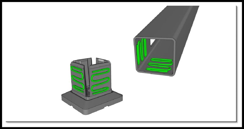
Apply the retaining compound. NOTE: Ensure that you fully understand the application
process of this compound BEFORE attempting to adhere the posts.
Clean outside faces of spigot, and inside faces of post with methylated spirits or acetone.
Apply compound on all spigot faces AND inside of post. Spread with finger (in glove) or paddle
pop stick or similar to ensure all faces have been covered entirely with a thin film of solution.
THIS IS EXTREMELY IMPORTANT. Failure to apply the compound correctly may result in an
unsafe or non-
compliant
Apply compound to
outside faces of the
spigot and inside faces
of the post.
Spread to ensure a
complete coverage of
adhesive
installation.
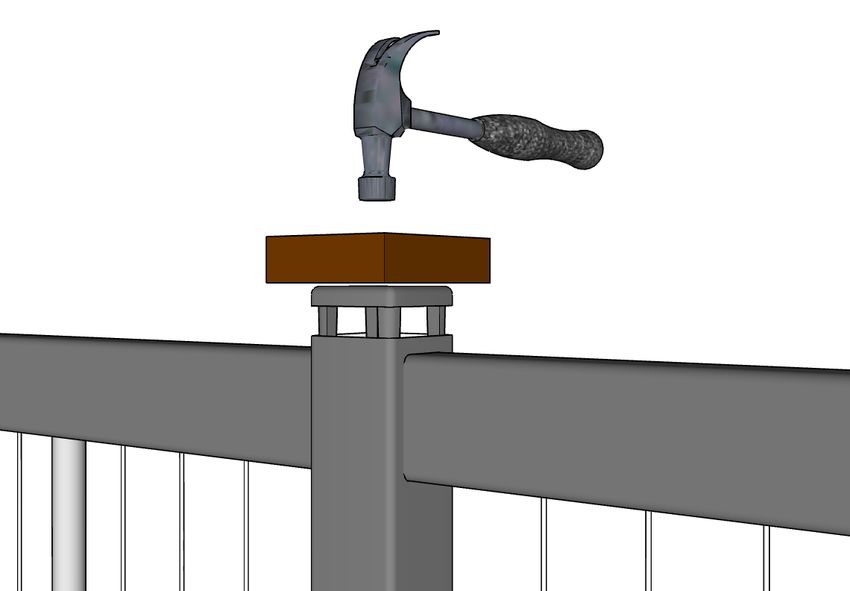
5Posts are then fitted by knocking down with a hammer and soft
block until firmly sitting on flange of spigot. NOTE: The retaining
compound will not begin to cure until contact is made between the
metal surfaces.
Immediately the post comes into contact with the spigot, the
bonding process has begun. You will only have a minute to knock
the post down fully into position, and bring to plumb. Work as fast
and as accurately as possible, as best results are obtained when
glue joint is made quickly.
Hold the post in plumb position (if necessary) for 5 - 10 minutes.
The compound will have grabbed sufficiently to hold the post in
place. The bond will be strong enough to continue work after an
hour, but will increase to maximum strength over a period of a week.
Ensure no undue force is exerted on the post in this period.
The retaining compound will only cure in the absence of air. Therefore excess solution can be
wiped off easily with a rag at any time. No solvents are required.
FITTING WALL BRACKETS (when used in combination with Sentrel posts)
Run a level out from the cut outs in the posts to the walls and/or existing posts in order to locate
the position of the brackets .
Truncated brackets are
the top brackets for
installations with handrail
Run a level out from post
cutouts to position
brackets
If your installation includes top handrail, position the truncated brackets as the top brackets with
the open face upwards.
Ensure that the small hole in the short wall of the bracket is located at the bottom. Fix the brack-
ets securely with appropriate screws (not supplied).
6FITTING PANELS
Panels are made to exact lengths and no trimming is required under normal circumstances.
However if it becomes necessary to shorten any of the panels, trim with a sharp tungsten carbide
blade on a drop saw.
Install panels as per the layout drawing by pushing one end all the way into a post/bracket, then
sliding it back so that the panel sits evenly in position.
Panels are supplied so that when properly installed the rail ends penetrate posts by 25 - 30mm
each end, and fully I nto the brackets.
13mm into Sentrel brackets
25 - 30mm into Sentrel posts
FITTING POST CAPS (for installations with no handrail)
Ensure that all panels are fitted
correctly and penetrate the posts
equally.
Position and knock down post caps
with a soft block and hammer. The fins
on the post cap will secure the rails into
the posts.
If panels mount to walls or existing posts, fix the top rail of the panel to the top bracket
through the hole in the base of the bracket with the Tek screws provided.
The installation is now complete.
7PREPARING FOR HANDRAIL
Lock all panels in place with the joiner plates and screws provided. NOTE: Make sure that the
correct panels are fitted to corresponding openings. Make sure that panels running between
Sentrel brackets (fitted to existing posts/walls) and Sentrel posts are oriented correctly. Cable
configuration is offset on these panels and will be marked accordingly.
Joiner plates
To prevent panels from slipping out of end posts, use the Tek screws (supplied).
Skew-screw through as shown, and be sure that the screws are positioned to sit against the
inside face of the posts.
Tek screws
FITTING TIMBER HANDRAIL
Using the handrail lengths supplied, cut and fit them to the top rail of the balustrade. Biscuit
joints and adhesive (Bostik AV 515 or similar) are recommended where handrail joins occur.
NOTE: The Sentrel system has been designed to be most structurally sound when handrail joins
DO NOT occur over the top of the posts. Joins must be at least 100mm clear of any handrail
mounting screws.
8Fix handrail in place with Hex Head screws (supplied) through the pre-drilled holes in the
underside of the top rail. NOTE: To avoid splitting, it is imperative to drill a pilot hole and screw
the batten screws in gently.
Join handrail away from posts and at least
100mm clear of handrail fixing screws
Glue infill pieces (supplied) to fill in handrail channel
where required.
Allow glue to set (about 1 hour, more is better). Trim
off excess and sand if necessary. Infill piece
FITTING ALUMINIUM HANDRAIL
Sentrel aluminium handrail simply clips to the top rail of the panels. Lengths can be cut with a
quality tungsten carbide blade on a drop saw. Care must be taken with all cuts as there is no
provision for filling joins. Accuracy is paramount for a neat installation.
Handrail clips onto
top rail of panel
Cut and fit mitre joins first.
Knock in place with hammer and wooden block,
taking care not to damage the painted finish.
9Cut and fit the remaining lengths. Use an appropriate colour touch up paint or a little coloured
silicon to finish between the joins. If using spray paint, ensure that you mask the outer surfaces of
the handrail to avoid overspray .
On short runs—especially on freestanding panels where handrail does not finish to a wall—it
may be necessary to apply a small amount of silicon on the underside of the handrail before
assembly to help prevent it moving. This will also be necessary on handrail fitted to stair panels.
Fit handrail end-caps if required— simply knock in
with timber block and hammer.
INSTRUCTIONS FOR FITTING STAIR PANELS
Stair panels are supplied straight and have flexible knuckles that allow the panel to be pushed to
the exact angle. Be sure that stair mounting posts have been positioned exactly in accordance
with the layout drawing. For fixing stair mounting brackets follow the same procedure described
for straight panels.
Push the panel to the correct angle
of the stairs. Be sure to push the panel Push panel
in the direction that the knuckles allow. Knuckle
Fit panels following the same
procedure described for straight
panels.
Using the long rivets supplied, fix
bottom rail to post/bracket at either
end.
Fix bottom rail
with long rivet
FINISHING UP
Clean down stainless steel poles with a suitable cleaner – White Spirit is ideal. Apply a suitable
protectant if the balustrade is in a aggressive environment (eg. near the ocean).
If you have installed a gate with hinges supplied by us, please note that these hinges are
ADJUSTABLE. Set to the lowest setting possible so that the gate closes positively but without
slamming.
10You can also read