AN ADVANCED MARS HELICOPTER DESIGN - SHANNAH WITHROW-MASER1 WAYNE JOHNSON2 LARRY YOUNG3 HALEY CUMMINGS1 ATHENA CHAN4 - NASA AMES RESEARCH ...
←
→
Page content transcription
If your browser does not render page correctly, please read the page content below
An Advanced Mars Helicopter Design

 Shannah Withrow-Maser1
 Wayne Johnson2
 Larry Young3
 Haley Cummings1
 Athena Chan4
 NASA Ames Research Center, Moffett Field, CA, 94035, USA

 Theodore Tzanetos5
 J. Balaram5
 Jonathan Bapst5
 NASA Jet Propulsion Laboratory, Pasadena, CA, 91109, USA

 Ingenuity may be the first of many Mars aerial vehicles. Rotorcraft increase the range and
 speed that can be traveled to locations of interest. This enables mission concepts previously
 considered not viable on Mars, such as missions performing science investigations in regions
 of high elevation, steep terrain, caves/lava tubes, and surveys of the lower atmosphere. Recent
 work done at NASA Ames Research Center and NASA’s Jet Propulsion Laboratory (JPL)
 show that significant science can be performed by rotorcraft either independently or as
 assistants to rovers and landers. Small rotorcraft of Ingenuity’s general size can be potentially
 integrated into missions already scheduled for launch. Additionally, larger rotorcraft can
 support standalone novel mission concepts but are still be able to be sized and configured for
 deployment from heritage entry, descent, and landing (EDL) systems. One such mission
 concept of interest is to determine if organics are associated with clay-bearing or silica-rich
 soil. For such a mission, a small rotorcraft “robotic assistant” to a lander or rover could help
 determine if ancient sediment contains biosignatures in regions such as Mawrth Vallis.
 Ingenuity has demonstrated that rotorcraft can be developed relatively quickly and
 inexpensively and increase the types and amount of science that can be performed on any
 given mission. Recent research has suggested that rotorcraft of Ingenuity’s general size can
 have their performance characteristics significantly enhanced – increasing their range, speed,
 and payload capacity – by using new generation rotor blade airfoils optimized for Mars
 operating conditions. Rotorcraft could potentially be a standard adjunct to all future lander
 and rover missions. This paper presents an advanced Mars helicopter design that leverages
 significantly the design heritage of the Ingenuity Mars Helicopter Technology Demonstrator
 (MHTD).

1
 Member; Aeromechanics Office, NASA Ames Research Center, Moffett Field, CA.
2
 Fellow; Aeromechanics Office, NASA Ames Research Center, Moffett Field, CA.
3
 Associate Fellow; Aeromechanics Office, NASA Ames Research Center, Moffett Field, CA.
4
 Student intern, Temple University, Aeromechanics Office, NASA Ames Research Center, Moffett Field, CA.
5
 NASA Jet Propulsion Laboratory, Pasadena, CA.

 1
I. Introduction
 Ingenuity, the 2020 Mars Helicopter, will likely be the first of many “ride along” rotorcraft carried to the surface of
Mars as well as other planetary bodies such a Titan and Venus. Ingenuity will demonstrate powered flight for the first
time on another planet, which, in turn, will enable science in regions previously labeled “unreachable” by rovers or
landers. Additionally, rotorcraft allow a larger region to be covered more quickly than a rover working alone, can
gather samples beyond the immediate reach of landers, and can improve imaging or sensing resolution over that of
orbiters. Recent collaborative effort by NASA’s Jet Propulsion Laboratory (JPL) and NASA Ames Research Center
(ARC) have shown that the performance of Mars rotorcraft can be significantly improved with non-traditional,
advanced airfoils enabling higher tip speeds and higher flight speeds. Increasing the blade area and having a larger
motor and battery results in much higher lift capabilities for an aircraft with the same rotor radius and a size comparable
to Ingenuity. The packaging of Ingenuity alongside Perseverance and the integration of the rotorcraft in a relatively
short timeframe into the 2020 Mars mission, demonstrate that it is reasonable to add these vehicles alongside future
rovers and landers in order to cover more surface area and conduct more science for the cost of a launch. The
adaptations described above were applied to Ingenuity design heritage to create a more capable, conceptual design for
an Advanced Mars Helicopter (AMH) which represents a modest technology evolution and represents a reasonable
candidate for the next rotorcraft to fly to Mars.

 II. Background
 Ingenuity will be the first Mars rotorcraft, but, utilizing rotorcraft on Mars as science “platforms” is not a new
concept. Young and others have been proposing rotary-wing-enabled exploration of the planet since 2000 (Refs. 1-5).
Recent technological advances in aerodynamic performance, autonomy, and power systems have enabled this first
non-terrestrial helicopter to be designed, fabricated, tested, and launched, with expected flights in the Martian
environment in early 2021. The primary challenge to flying a rotorcraft on Mars is presented in Balaram et al. (Ref
6), “The challenge to helicopter use on Mars is the thin carbon dioxide atmosphere with approximately 1% of the
density of Earth’s atmosphere.” However, the required autonomy, limited communications, ultra-lightweight rotors,
flight controllability issues, and limited available power are nontrivial considerations. These requirements, as
challenging as they were for Ingenuity, will be even more demanding for next generation Mars rotorcraft to perform
science missions as an adjunct to, or independently, of a rover/lander. Early collaborative work at NASA Ames
Research Center (ARC) and NASA’s Jet Propulsion Laboratory (JPL) had focused on a new generation of rotorcraft,
called generically Mars Science Helicopter(s), that are larger, faster, carry more payload, and flyer longer than the
first generation Mars rotorcraft, Ingenuity (Ref. 7 and 8). These vehicles are capable of operating in conjunction with,
or independently of, rovers and landers. These initial second generation Mars rotorcraft conceptual designs were on
the order of 20-30 kilograms in size but could also be packaged so as to fit within legacy, or near-legacy, entry,
descent, and landing (EDL) systems. This early work was introduced in Ref. 7 and expanded on in Ref. 8. These
studies proposed two primary classes of future Mars rotorcraft: in addition to large, scaled coaxial, or multirotor,
configurations designed for independent/standalone science missions, smaller, Ingenuity-sized vehicles were also
proposed that would interact with a larger rover or a lander based ground-station (Figure 1). The mission description
and motivation for the Mars Science Helicopter (MSH) study are described in Ref. 9. Areas of research and technology
for the second-generation vehicles include airfoil optimization, rotor performance, packaging, rotor and frame
structural analysis, preliminary guidance, navigation, and controls, and accommodation of science instrument
payloads. Each of these vehicle designs benefits from lessons learned during the development of Ingenuity. This paper
will focus on the application of technology developed initially in support of the larger MSH concepts to a vehicle of
the same diameter as Ingenuity, known as the “Advanced Mars Helicopter” (AMH).

 2
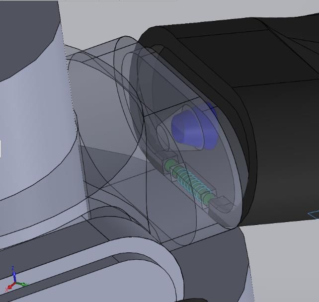
Fig. 1. Mars second generation rotorcraft concepts with Ingenuity for scale.

 Ingenuity is a 1.21 m diameter, 1.8 kg rotorcraft in a coaxial configuration, and will be used as the reference design
for the duration of the paper. Ingenuity has a camera for navigation, but does not have any science instrumentation
apart from what is required for flight. Ingenuity’s mission includes a series of 90 second autonomous flights of
increasing difficulty, serving as a technology demonstration of the first powered flight on another planet (Ref. 6). In
the future, rotorcraft of this size could be used to assist the first human explorers of the red planet, in addition to
conducting science alongside rovers and landers or independently.

 III. Advanced Mars Helicopter Design and Performance
 The AMH inherits the heritage size and configuration of Ingenuity. However, recent technology advancements
suggest that a rotorcraft of similar size and form can go from having no payload to being able to carry a ~1.3 kg
science payload. Accordingly, this class of small advanced rotorcraft is therefore ideal for future cooperative rotorcraft
and rover, or rotorcraft and lander, missions. For these missions, the rotorcraft acts almost as any other science
instrument, albeit deployable and mobile, to a rover or lander. For example, the AMH design could collect and return
soil, rock, or ice samples to a lander where heavier equipment could be used to process the samples. AMH could also
accompany a rover acting as a scout, to determine the most direct and safest route for the rover, as well as identifying
nearby high-value science targets for in-situ exploration. These advantages come at a relatively low price as Ingenuity
has already demonstrated that it is feasible to integrate rotorcraft as “assistants” to rover and lander-centric missions.
For context, Ingenuity has a mass of 1.8 kg, while Perseverance has a mass of 1,056 kg; rotorcraft can be folded and
stowed to ride beside, or even underneath, larger vehicles.

 A. NDARC vehicle sizing

 NASA Design and Analysis Code (NDARC) was used to size the AMH design with the same rotor radius as
Ingenuity. NDARC has been validated against and used to size many terrestrial rotorcraft and has been used as a key
analysis tool in the development of Ingenuity, as well as the early MSH studies. Relevant AMH vehicle parameters
and assumptions can be found in Table 1. Table 2 shows the comparison of key performance parameters to Ingenuity.
Advanced airfoils, more blade area, and large batteries and motor account for these differences and result in higher
tip speed, flight speed, and the ability to carry a larger science payload.

 3
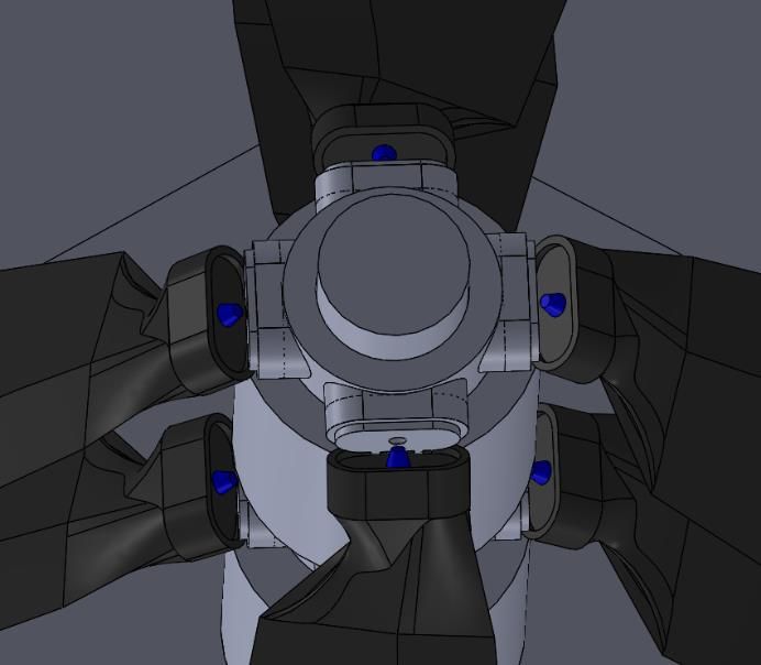
Table 1. AMH vehicle parameters.
 Units Value
 Constants
 3.711
 Gravity 2
 0.015
 Density 3

 - -
 Vehicle Parameters
 m 0.605
 Rotor radius
 kg 4.6
 Gross Mass
 1.3
 Payload Mass kg
 - 4
 Number of Blades
 1 2
 Flap Freq
 - 0.12
 Lock number
 39.310
 Disk Loading 2
 kW 0.587
 Power req. for hover

Table 2: Ingenuity and AMH comparison.

 4
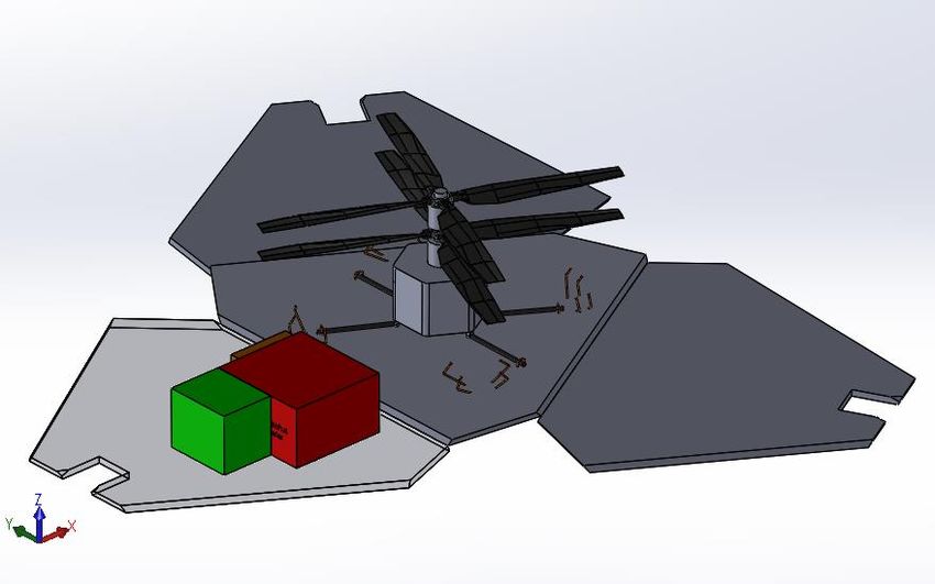
Figure 2 shows the potential increase in terms of range and hover time with advanced airfoils and design
parameters as defined in Table 2.

 Fig. 2. Hover time versus range: Ingenuity and AMH.

 B. Rotors and advanced airfoils

 Thin airfoils with sharp leading edges have been shown to provide a significant increase in performance compared
 to Ingenuity’s blades (Ref. 10-13). Such performance improvements as seen in Figure 2 are due primarily to the use
 of nonconventional airfoils. Flight on Mars occurs in the low Reynolds number (Re) (~104), high subsonic Mach
 number (~0.8 at the tip) regime, which is not typically found in flight on Earth. Thus, ideal airfoils for Mars may
 look different than those conventionally used on terrestrial rotorcraft. At low Re, conventional airfoils experience
 laminar separation with no reattachment, which significantly increases drag. Animals in nature that fly in this low
 Re flight regime (such as the dragonfly) exhibit thin, unconventional airfoil shapes (Figure 3, Ref. 14). Koning
 discussed the increase in performance for thin airfoils with sharp leading edges compared to Ingenuity’s blades
 (Ref. 10-13). These sharp leading edges immediately cause the flow to separate. Subsequently, unsteady vortex
 shedding is seen to actually cause an increase in performance compared to conventional airfoils at these very low
 Reynolds numbers. Compared to Ingenuity, an increase of up to 41% in peak lift-to-drag ratio can be achieved with
 an initial set of optimized airfoils.

 Fig. 3. Low Re airfoils. (Ref. 10 and 14).

 With this initial set of optimized airfoils, rotor blade twist and planform were also optimized using the well-known
rotorcraft analysis software code CAMRAD II and the NDARC sizing tool used to predict and maximize performance.
Blade taper and twist were varied to converge upon the optimum values. Using optimized airfoils, taper, and twist, an
estimated Figure of Merit of 0.62 (~7% higher than Ingenuity) is achievable for the AMH as well as a significantly

 5
expanded maximum thrust capability prior to rotor stall in hover. Figure 4 illustrates the airfoils and the planform
distribution of the AMH optimized rotor blade.

 Fig. 4. Optimized rotor for second generation Mars vehicles (Ref. 8).

 Research is still ongoing to determine the right balance for Mars rotor blade design between aerodynamic
performance and blade weight, stiffness, strength, and frequency placement. Thin airfoils with sharp leading edges
result in rotors with lower overall flap bending and torsion stiffness. The smaller aerodynamic loads that result from
the low Mars atmospheric density mean that less stiffness is required from a purely aerodynamics perspective.
However, flap mode frequency is critical for cyclic control of a coaxial helicopter, so the structural design of the rotor
must take this into account. Initial studies show that sufficient controllability and stiffness is possible using carbon
fiber skin, foam core, and aluminum root insert (Ref. 8).

 The ROAMX (Rotor Optimization for the Advancement of Mars eXploration) project at Ames was recently funded
through the NASA Space Technology Mission Directorate (STMD) Early Career Investigator program. ROAMX will
perform further airfoil and rotor optimization and structural studies using computational models. The ROAMX team
will verify these models through experimental testing in the Planetary Aeolian Laboratory low-pressure chamber at
Ames where work for Mars rotorcraft research has previously been conducted (Ref. 3 and Ref. 15). This work will
result in a validated design methodology that can be applied to all future Mars rotorcraft rotor designs.

 IV. Mission Potential
 A successful flight for Ingenuity will enable many science missions previously thought to be infeasible. Traditional
EDL systems require relatively flat initial landing sites with minimal potential for collision with surface features.
Larger, ground based vehicles then perform missions within a limited range of the landing site. Rotorcraft, however,
possess the ability to land in “safe” region and travel to an area of interest (such as crater rims, cliffs, caves, etc.) to
perform science at close range.

 Balaram et al. discussed regions of potential interest for a Mars Science Helicopter (Ref. 9). Estimated payload
capacities of these future generation helicopters on Mars could enable science such as geologic mapping, excursions
to exposed ice deposits, astrobiology, and meteorology utilizing instrumentation such as thermal imagers, X-ray
spectrometers, tunable laser spectrometers, imaging radars, visible-near infrared (VNIR) spectrometers, and light
detection and ranging (LIDAR).

A. Geologic and/or Ice Surveys

 Two examples of high-interest science investigations are geologic mapping and studying exposures of water ice,
ranging from the mid-altitude regions to the poles of Mars, as identified by the Mars Exploration Program Assessment
Group (MEPAG) (Refs. 15-18). Determining stratigraphic relationships in the geologic record provides insight into
the climate and geologic history of Mars (Ref. 19). Rotorcraft can collect high-spatial-resolution imagery to produce
detailed maps of Martian terrain, as compared to that of orbiter imagery, at a more efficient rate than landers/rovers.
Additionally, while rovers are unable to transverse steep terrain or un-traversable surface material, small rotorcraft
can fly and hover over these terrains, for example exposed water ice scarps, and could characterize surface properties

 6
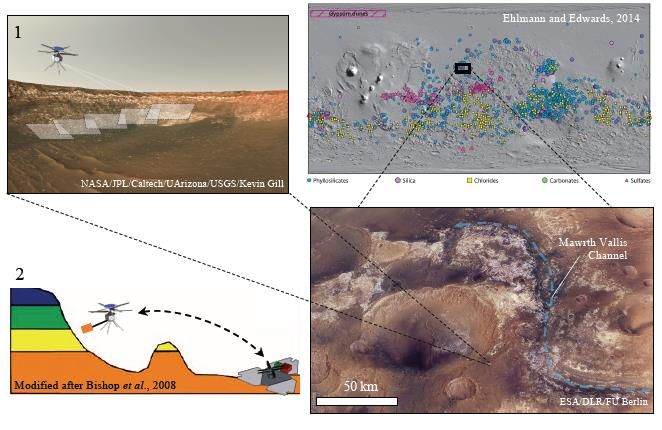
and processes at greater fidelity than assets in orbit (e.g., texture, geometry, sublimation rates, and atmospheric
interaction). After collecting data and samples, thea)rotorcraft can return to the original landing site
 b) to take advantage
of larger, heavier scientific and communication instrumentation built into the lander (Ref. 20).

B. Clays and astrobiology mission

 Bapst, et al. described compelling science for the next decade enabled by Mars rotorcraft in a mission concept
white paper submitted to the 2023-2032 Decadal Survey on Planetary Science and Astrobiology (Ref 21). In this
paper, Bapst outlines a specific mission concept that would be ideal for the size of rotorcraft described above. Bapst
states: c) d)

 Mawrth Vallis is a large outflow channel spanning ~640 km located in northwest Arabia Terra near 343°E, 22°N,
 at approximately –3000 m elevation. Along the channel are some of the clearest detections of phyllosilicate
 minerals (clays) on the planet, which were likely deposited more than 3.5 Gyr ago (Fig. 5). Detections mapped
 from orbit [ref 19–21 of Bapst, et al.] provide a window into early Mars and indicate periods of intense aqueous
 activity, both at the surface [ref 22 of Bapst, et al.] (e.g., wetlands/ponds) and in the subsurface (e.g., impact
 generated hydrothermal systems). In addition to revealing aqueous activity on early Mars, these minerals are
 known to preserve organic material on Earth…MSH would, if necessary, drill or disaggregate rock, followed by
 collection and delivery to a lander for subsequent physical and chemical analyses. The ability to travel a long range
 in a short period of time, and reach hard-to-access sites, in situ, allows for a more-selective approach in sampling—
 or if adequate samples are rare—the ability to visit many locations to find one suitable.

 The goals of the mission described above would be to 1) determine if organics are associated with clay-bearing or
silica-rich units, and 2) determine if ancient sediment contains biosignatures. The instrumentation would be divided
among AMH for in-situ science (sampling arm and microdrill) and a lander (gas chromatograph mass spectrometer,
micro-imaging suite, and life detection instrument).

 Fig. 5. (a) AMH identifying regions of interest. (b) Global detections of aqueous minerals. (c) Retrieval of
samples and delivery to a lander that hosts instrumentation. (d) Perspective view of Marwth Vallis and crater
 exposing materials of interest (Ref 21).

 V.Rotorcraft Packaging in EDL Systems and Deploying from Landers or Rovers
 Before performing science on Mars, the rotorcraft must first survive the launch and journey to the surface of the
planet. The thin, stiff rotor blades could be especially susceptible to damage if not packaged properly.

 7
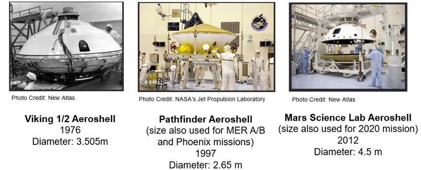
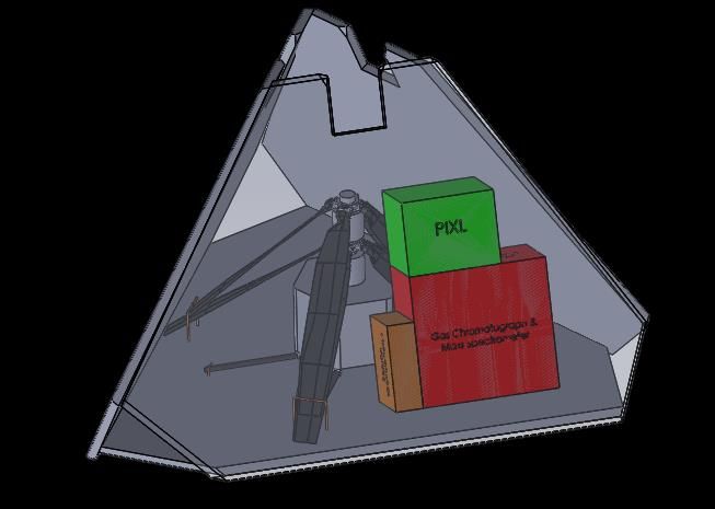
A. Volume Study and Estimation

 A vehicle packaging study was performed, using the clay and astrobiology mission as a reference mission. It was
assumed that adapting a heritage EDL system for a Mars rotorcraft of the size of the AMH class of vehicle would
minimize cost to schedule and budget of a future Mars mission, rather than developing a new EDL system. Three
systems were investigated including those used for the Pathfinder, Viking, and Mars Science Lab/Perseverance
missions (Figure 6).

 Fig. 6. Heritage aeroshells for Mars missions.

 Of the three EDL systems, Pathfinder is the smallest and least expensive to launch. As such, the Pathfinder
tetrahedral petal lander and aeroshell were used as the baseline EDL system for the vehicle packaging study. The
AMH design was adapted to allow for rotor blade and landing gear folding to fit within the Pathfinder tetrahedral
lander. Once a folding configuration was confirmed to successfully fit in the lander, various positions and folding
methods were explored to maximize volume available for other mission instrumentation and payloads. Figure 7
illustrates several different arrangements of the AMH rotorcraft and other auxiliary science payloads. In Figure 7, the
medium sized-green box included with the folded rotorcraft within the lander is approximately the volume of the x-
ray lithochemistry system (based on Perseverance PIXL); the large, red volume approximates the gas
chromatographer/mass spectrometer; and the small, orange box approximates the raman spectrometer. Figure 8
illustrates where batteries (blue) and micro-drill (yellow) are incorporated into the rotorcraft.

 8
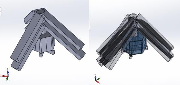
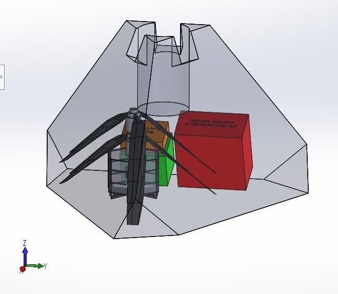
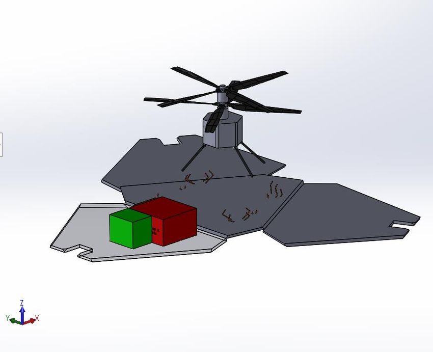
a) b)

 c) d)

 Fig. 7. AMH in Pathfinder tetrahedral petal lander at a) angled, b) flat, c) sideways, and d) offset positions
 along with boxes represeting payload volume.

 Fig. 8. Battery and micro-drill volumes relative to the internal rotorcraft volume.

 Other MSH vehicle configurations, such as a 20-30 kilogram hexacopter and large coaxial helicopter (which also
carry larger payloads), are constrained by the size of the Pathfinder lander and, consequently, challenging to
adequately package. However, the smaller AMH, which was designed with a rotor radius of the same size as the
Ingenuity rotors, has multiple viable folding configurations with a Pathfinder-type tetrahedral petal lander. (Note that
the clay and astrobiology mission - and this volumetric study – implies a lander/rotorcraft mission CONOPS whereby
the rotorcraft periodically flies from and back to the lander to perform aerial surveys and transfer data and samples to
the lander.) While the ‘sideways’ configuration occupied the least volume of the configurations shown (Figure 7), it
is also more mechanically complex to unfold. Furthermore, the volume saved was not critical for preserving
space/volume for the other auxilliary science instrumentation for the reference astrobiology mission studied.
Accordingly, mechanical robustness and simplicity were prioritized in the selection of the final folding configuration,
(‘flat with blades drooped’) (Figure 9).

 9
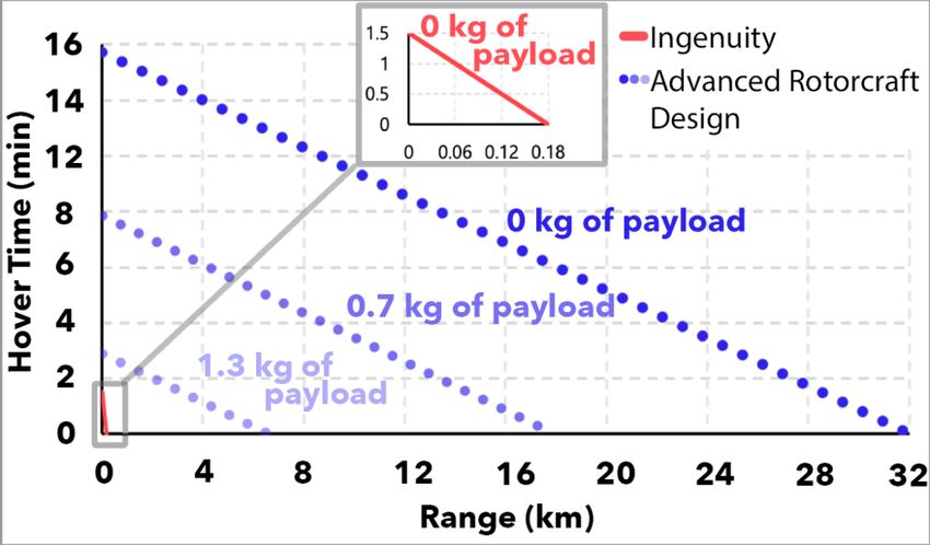
Fig. 9. Selected packaging configuration for AMH and payloads inside Pathfinder’s tetrahedral petal
 lander.

 As mentioned previously, simple volumetric models of required instrumentation for the clay and astrobiology
mission, as described in Baspt (Ref. 21), were placed in the lander with the rotorcraft. Additionally, accounting for
the batteries and payload, usable interior volume for avionics and additional electrical and mechanical systems in the
rotorcraft fuselage interior was approximated to be ~40 cm3. Usable lander volume was defined as volume that could
reasonably be used for required subsystems and payload (i.e. excluding small spaces between rotors, legs, etc.) by
creating a simplified model (Figure 10) of the rotorcraft that represented dedicated volume needed in the lander for
the rotorcraft. Usable volume available in the lander was estimated to be ~480 cm3. This volume is available for
communication hardware, rotorcraft solar panels, and additional payload.

 Fig. 10. AMH simplified volume ‘mock’ model (left); simplified volume model overlaid on the AMH vehicle
 (right).

B. Stowage, Activation (or Deployment), and Locking Mechanisms

 After lander volume proof-of-concept requirements were satisfied, the next step towards assessing EDL feasibility
was to explore the requirements for the rotorcraft to leave the lander once it is safely on the Martian surface. The
transition from “stowed mode” to “flight mode” can be broken down into three phases: stowage, activation (or
deployment), and flight mode. For this discussion, stowage refers to the state of the rotorcraft while in transit to Mars
and while landing on the surface (Figure 11). Activation is the phase that encompasses the release of clamped and
tethered components, using passive or active actuation to unfold the rotorcraft components, and transition into and
readiness for entering flight state (Figure 12). Flight state refers to the rotorcraft being free of constraints and in

 10
position to begin the mission sequence (Figure 13). The lander petals open and the rotorcraft and lander-based
instrumentation systems are oriented into their proper deployed positions. (Note that it is assumed that the Pathfinder
design heritage of airbags and the actuation mechanisms to unfold/orientate the tetrahedral petals is retained.) The
rotorcraft blades are then unfolded from their canted stowed position and then the rotorcraft as a whole is raised
through another actuation mechanism to a vertical position where the folded landing legs can unfold and snap into
their flight-ready positions.

 Fig. 11. AMH in the stowed position.

 Fig. 12. AMH in the process of activation; transitioning from stowed to flight mode.

 Fig. 13. AMH blades in flight mode.

 11
It was necessary to fold the blades from their flight position in order to fit in the tetrahedral petal lander. The
simplest method of folding that does not significantly compromise the stiffness of the blades was to place a hinge at
the root of the blade; refer to Figure 14. Furthermore, since it is difficult to accommodate a hinge along a circular
surface, the spar at the root of the blades was modified into an oblong shape (Figure 14). To avoid interfering with the
aerodynamic performance, the inner 20% of this spar may be used to house hinges, springs, locks, and other
components, but the outer 80% must maintain the airfoil shape. The primary consideration to any blade modification
for this type of application is that the leading edge of the blade must maintain the same thickness and shape (curvature).
Additionally, stiffness of the blade must be maintained to avoid excessive flapping to achieve acceptable
controllability. This will require follow-on hinge mechanism design work to ensure the maximum stiffness of the
blade in the unfolded position.

 Fig. 14. Blade hinge placement.

 One possible combination for blade unfolding actuation is pyrotechnic cutters (to cut two sets of wires securing
the blades to the lander during flight) and loaded torsions springs to release the blades and allow them to move into
place (Figure 15). Once the AMH is ready to transition into flight mode, the pyrotechnic cutters on the upper wires
will activate, releasing the upper blades (Figure 16). Next, the lower blades will be released and will spring into place
(Figures 17 and 18).

 Fig. 15. Spring-loaded blade hinge.

 12
Fig. 16. Close up of already-activated upper blade wire and still-secured lower blade wire.

 Fig. 17. Released upper blades and stowed lower blades.

 Fig. 18. Released upper and lower blades.

 Other possible methods of activating the blades into flight mode include the use of motors, tethers, and rotation.
Additionally, several locking designs to secure the blades into their final positions have been explored including: a fin

 13
lock (similar to a toggle bolt), sealing fin lock (uses a compressible material), magnetic lock, and spring lock (similar
to the leg locks on Ingenuity) all internal to the spar structure. It is currently assumed that the landing gear will maintain
the heritage design of Ingenuity for springing and locking in place. Figure 19 shows the vehicle in flight mode. Follow-
on work in this critical deployment/activation area will continue.

 Fig. 19. AMH in flight mode.

 Left for future work is the conceptual design of the lander subsystems to make it a fully functional base-station
for the rotorcraft. This includes solar arrays on the lander petals, power electronics to supply all instrumentation and
subsystems on the lander (and to perhaps be an alternative source of power for the rotorcraft), telecommunications
equipment, robotic arms for sample transfer from the rotorcraft to science instruments on the lander, and perhaps a
small tethered/untethered transfer rover to carry empty and full sample tubes to and from the lander and the rover for
the final few meters between the rotorcraft landing site next to the lander and the lander itself. The whole process of
the robotic symbiosis between the lander and rover needs to be defined in future work beyond the very high-level
ideas detailed to date. An understated element of design heritage from Ingenuity is onboard solar electric recharging
of the vehicle for multiple sortie flights. This capability is retained in the proposed AMH. This, in turn, implies a
sustained robotic partnership between AMH and the lander base-station.

 VI. Conclusion
 The use of rotorcraft on Mars, and other planetary bodies with sufficient atmospheric mass, has the potential to
complement both the speed and area covered by orbiters and the proximity of land vehicles to objects of interest,
without as many terrain-based limitations. With low mass and volume compared to landers and rovers, rotorcraft can
accompany these larger vehicles at relatively low cost and risk to the mission, while providing significant advantages.
Because these rotorcraft can easily integrate into heritage EDL systems such as the Pathfinder lander or a lander/rover
in a Mars Science Lab sized aeroshell, development teams can focus valuable time and energy on the science enabled
by these aerial platforms. The fast development, testing, integration, and launch of Ingenuity demonstrates that it is
feasible to launch this type of vehicle regularly, suggesting that, perhaps, rotorcraft should be a part of every future
Mars mission. In the future, in addition to conducting science alongside rovers and landers or independently, rotorcraft
of this size could be used to assist the first human explorers of the red planet .

 Acknowledgments
 The authors would like to acknowledge the interns of the NASA Ames Aeromechanics Branch who have
 contributed to this work including Winnie Kuang, Allysa Tuano, and Sara Mayne. The authors would also like to

 14
thank Natalia Perez-Perez for generating Figure 2. Lastly, the authors would like to thank all members of the NASA
Ames and JPL community who have contributed to and supported the study of Mars rotorcraft.

 References
 [1] Young, L. A., Chen, R. T. N., Aiken, E. W., Briggs, G. A., "Design Opportunities and Challenges in the
 Development of Vertical Lift Planetary Aerial Vehicles," Proceedings of the American Helicopter Society
 International Vertical Lift Aircraft Design Conference, San Francisco, CA, January 2000.
 [2] Young, L.A., “Vertical Lift – Not Just For Terrestrial Flight,” AHS/AIAA/RaeS/SAE International Powered
 Lift Conference, Arlington, VA, October 30 – November 1, 2000.
 [3] Young, L.A. and Aiken, E.W., “Vertical Lift Planetary Aerial Vehicles: Three Planetary Bodies and Four
 Conceptual Design Cases,” 27th European Rotorcraft Forum, Moscow, Russia, September 11-14, 2001.
 [4] Datta, A., Roget, B., Griffiths, D., Pugliese, G., Sitaraman, J., Bao, J., Liu, L., Gamard, O. “Design of a
 Martian Autonomous Rotary-Wing Vehicle,” Journal of Aviation, Vol. 40, No. 3, 2003.
 [5] Lacerda, M., et al. “Georgia Tech Mars Exploration UAV Collaborative System: A Conceptual Design and
 Systems Engineering Study.” SMARTech Home, Georgia Institute of Technology, 2017.
 [6] Balaram, J., et al., “Mars Helicopter Technology Demonstrator,” AIAA Science and Technology Forum and
 Exposition (AIAA SciTech), 2018.
 [7] Withrow-Maser, S., Koning W., Kuang W., Johnson, W., “Recent Efforts Enabling Future Mars Rotorcraft
 Missions,” Vertical Flight Society’s Aeromechanics for Advanced Vertical Flight Technical Meeting, San
 Jose, CA, 2020.
 [8] Johnson, W. R., Withrow, S. N., Young, L. A., Malpica, C., Koning, W. J., Kuang, W., Fehler, M. E., Tuano,
 A. M. B., Chan, A., and Datta, A., Mars Science Helicopter Conceptual Design, NASA/TM-2020-220485,
 Moffett Field, California, 2020.
 [9] Balaram,J., Daubar, I. J., Bapst, J., and Tzanetos, T., “HELICOPTERS ON MARS: COMPELLING
 SCIENCE OF EXTREME TERRAINS ENABLED BY AN AERIAL PLATFORM,” Ninth International
 Conference on Mars, 2019.
 [10] Koning, W. J., Romander, E. A., and Johnson, W., “Optimization of Low Reynolds Number Airfoils for
 Martian Rotor Applications Using an Evolutionary Algorithm,” AIAA SciTech 2020 Forum, American
 Institute of Aeronautics and Astronautics, Orlando, Florida, 2020.
 [11] Koning, W. J. F., Romander, E. A., and Johnson, W., “Performance Optimization of Plate Airfoils for Martian
 Rotor Applications Using a Genetic Algorithm,” 45th European Rotorcraft Forum 2019 (ERF), Vertical
 Flight Society, Warsaw, Poland, 2019.
 [12] Koning, W. J. F., Johnson, W., and Grip, H. F., “Improved Mars Helicopter Aerodynamic Rotor Model for
 Comprehensive Analyses,” AIAA Journal, 57(9), 2019, pp. 3969–3979.
 [13] Koning, W. J. F., Johnson, W., and Allan, B. G., “Generation of Mars Helicopter Rotor Model for
 Comprehensive Analyses,” AHS Specialists’ Conference on Aeromechanics Design for Transformative
 Vertical Flight, American Helicopter Society, San Francisco, California, 2018.
 [14] Lissaman, P. B. S., “Low-Reynolds-Number Airfoils”, Annual Review of Fluid Mechanics, Vol. 15, 1983,
 pp. 223–239.
 [15] Perez Perez, B. N., Ament, G.A., and Koning, W. J. F., “Experimental Forward Flight Rotor Performance
 Testing From Terrestrial to Martian Atmospheric Densities,” NASA/CR–2019–220229, 2019.
 [16] Baker,D., and Carter, L.. “Probing Supraglacial Debris on Mars 1: Sources, Thickness, and Stratigraphy,”
 Icarus, Vol. 319, 2019, pp. 745-769.
 [17] Becerra Valdes, P.,Sori, M., Thomas, M. N., Pommerol, A.,Simioni, E., Sutton, S. ,Tulyakov, S., Cremonese,
 G., “Timescales of the Climate Record in the South Polar Ice Cap of Mars,” Geophyscial Research Letters,
 2019.
 [18] Banfield, D., et al. “Mars Science Goals, Objectives, Investigations, and Priorities: 2020 Version.” Mars
 Exploration Program Analysis Group (MEPAG), 2020.
 [19] Koeppel, A., and Edgar, L., “Recognizing Stratigraphic Diversity Through 1:10,000 Scale Geologic Mapping
 of Northwest Aeolis Mons, Mars” Annual Meeting of Planetary Geological Mappers, Flagstaff, Arizona,
 2019.
 [20] Withrow-Maser, S., Cummings, H., and Bapst, J., “Rotorcraft Platforms Enabling Future Mars Science
 Missions,” 2020 International Planetary Probe Workshop, Virtual, June 2020.
 [21] Bapst, J., et al., “Mars Science Helicopter: Compelling Science Enabled by an Aerial Platform,” White Paper
 submitted to 2023-2032 Decadal Survey on Planetary Science and Astrobiology, 2020.

 15
You can also read