Analytical and Numerical Study for Mass Loading Effect on Natural Frequencies of Aluminum Alloy Propped Cantilever Beam
←
→
Page content transcription
If your browser does not render page correctly, please read the page content below
Published by : International Journal of Engineering Research & Technology (IJERT)
http://www.ijert.org ISSN: 2278-0181
 Vol. 10 Issue 06, June-2021

 Analytical and Numerical Study for Mass
 Loading Effect on Natural Frequencies of
 Aluminum Alloy Propped Cantilever Beam
 Ayush Kumara, Anuj Yadavb and Hirendra Singhc
 a,c
 Department of Mechanical Engineering, Naraina College of Engineering and Technology, Kanpur - 208020, India
 b
 Department of Mechanical Engineering, National Institute of Technology, Patna - 800005, India

 Abstract— A lot of attention has been received to frequency of a beam in a free-free end conditions was
determine the natural frequencies of a continuous system. studied in this paper. Prashant et al. [7], experimental
Engineers are more interested in evaluating the dynamic modal analysis of cantilever beam was carried out to obtain
behavior of a beam since it is one of the most essential natural frequencies, modal damping, and mode shapes.
continuous structures. The objective of the article is to study
the impact of mass loading on the natural frequency of
 Yadav and Singh [8, 9] investigated the mass attachment
aluminum alloy propped cantilever beam. Analytical and impact on vibrational frequencies of cantilever and simply-
numerical methods are used to model the dynamic behavior of supported magnesium alloy beams. Caker and Sanliturk
the beam mass system. An Euler-Bernoulli beam of fixed- [10] and Ren et al. [11] presented a new approach for
hinged end conditions carrying a point mass at an arbitrary removing mass loading effects of transducers from
position has been considered for analytical studies. The non- calculated FRFs, based on the Sherman–Morrison concept.
dimensional frequency equation for beam fixed-hinged end Any physical problem can be solved with help of exact and
conditions is obtained by satisfying the free vibration approximate methods but most of the problems are solved
equations of motion and by applying the corresponding end by an approximate method due to its complexity. In this
and compatibility conditions. This boundary-value problem is
solved by a dual frame of reference. Simulation of the
 paper, the modal analysis of the beam-mass system has
problem is done by using ANSYS and the validation of the been examined by approximate analytical and numerical
proposed analytical method is demonstrated utilizing methods.
simulated data. It has been observed that the natural 2. ANALYTICAL SOLUTION
frequencies of the beam are influenced by the mass position An Euler-Bernoulli beam of length (L) 240 mm, fixed-
and its magnitude. hinged end conditions with attaching a point mass (m) of
 23 gm at an arbitrary position have been considered for
Keywords— ANSYS; Propped cantilever beam; MATLAB; analytical studies. It is an aluminum alloy beam having a
Eigenfrequency dimension of 240×12×6 mm and beam's material properties
 1. INTRODUCTION like as Young's modulus 71GPa and density is 2770 Kg/m 3.
 Free vibration of combined structures is a popular issue A dual frame of reference has been used to solve this
in today's world. This issue affects a wide range of beam-mass system (Fig. 1) problem. By satisfying the free
engineering design disciplines. The most of the research in vibration equations of motion and applying the related end
this field focuses on the discovery and application of and compatibility conditions, the non-dimensional
methods for determining the combined system's natural frequency equation for beam fixed-hinged end conditions
frequencies. Rao [1], the basic governing equation for free has been obtained.
vibration for simple structure like Euler-Bernoulli beam is
available in reference book. Low [2], this study presents a
comparative review of the Eigen-frequency analysis for an
Euler-Bernoulli beam with a point mass at any position.
Mermertas and Erol [3] examined the Eigenfrequency
equation of a cracked cantilever beam with attached point
mass. Theoretical investigation of the cracked beam was
carried out. The governing equation of the cracked beam
for free vibrations is developed from the elements of the
Euler-Bernoulli beam. Naguleswaran [4], for the free
vibrations of a beam carrying two point masses, an Fig. 1. Propped cantilever beam with point mass
empirical approach based on the classical beam eigenvalue
method is presented in this article. Öz and Özkaya [5] The equation of motion for free vibration of a uniform
presented the Euler-Bernoulli beam with masses at various beam is given as
positions is considered in this research. For various
boundary conditions, natural frequencies for free transverse 4 2
 4 + 2 = 0 (1)

vibrations are studied. Kotambkar [6], the impact of mass
 The technique of separation of variable has been used to
loading caused by an accelerometer on the natural
 find the free-vibration solution.

IJERTV10IS060395 www.ijert.org 882
 (This work is licensed under a Creative Commons Attribution 4.0 International License.)
Published by : International Journal of Engineering Research & Technology (IJERT)
http://www.ijert.org ISSN: 2278-0181
 Vol. 10 Issue 06, June-2021

 ( , ) = ( ). ( ) (2)
 ( ℎ ) 2 + ( ) 2 + ( ) {( ℎ −

The characteristic function ( ) of the beam is defined as
 ) 1 + ( ℎ − ) 1 } = 0 (16)
 ( ) = 1 cosh + 1 sinh + 1 cos + 1 sin Let us assume

 (3) Dimensionless mass location parameter ( ) =

Where, 4 = ( 2 )
 1 = ℎ −

Where is the natural frequency.
 2 = ℎ −

 = 2√ (4) 3 = ℎ +

The dual frames of references have been taken to solve the 4 = ℎ +
problem.
 1 = ℎ (1 − )
 1 ( 1 ) = 1 cosh 1 + 1 sinh 1 + 1 cos 1 +
 1 sin 1 (5)
 2 = ℎ (1 − )
 2 ( 2 ) = 2 cosh 2 + 2 sinh 2 + 2 cos 2 +
 3 = (1 − )
 2 sin 2 (6)
The fixed end coordinate of the beam ( 1 = 0 =0 ) and at
 4 = (1 − )
hinged end coordinate ( 2 = 0 = ) , the fixed end
transverse displacement 1 ( , ) satisfies boundary
conditions ( 1 = 0 and 1′ = 0), 1 ( , ) can be expressed =

as The resulting dimensionless frequency equation in
 determinant form has been obtained by substituting the
 1 ( 1 ) = ( ℎ 1 − 1 ) 1 + ( ℎ 1 − equation number (10), (12), (14), and (16).
 1 ) 1 (7)
The hinged end transverse displacement 2 ( , ) satisfies 1 2 2 4
boundary conditions ( 2 = 0 and 2′′ = 0), 2 ( , ) can be 4 1 − 1 − 3
 | |=0 (17)
expressed as 3 4 2 − 4
 2 + 1 . 3 + 2 . − 1 3
 2 ( 2 ) = −( ℎ 2 ) 2 − ( 2 ) 2 (8) The values of βL for different vibrational modes have been
For further solution, four additional compatibility equations found out by solving the equation (17) in MATLAB
have been used software. It is observed that the values of βL in mode1, 2,
Transverse displacement equation at 1 = or 2 = and 3 change with respect to the point mass attachment
 locations. The natural frequencies of the beam-mass system
 1 ( 1 ) 1 = = 2 ( 2 ) 2= (9) in different modes are obtained by Eq. (4). The changes in
 the value of βL of different modes with respect to the
( ℎ − ) 1 + ( ℎ − ) 1 + dimensionless mass location parameter (α) have been
( ℎ ) 2 + ( ) 2 = 0 (10) represented in Table 1, Fig. 2, Fig. 3, and Fig. 4.
Slope equation at 1 = or 2 =
 Table 1. Changes in the value of βL of different modes with respect to α.

 1′ ( 1 ) 1 = =− 2′ ( 2 ) 2= (11) SI. No. α
 Mode I Mode II Mode III
( ℎ + ) 1 + ( ℎ − ) 1 − 1 0.1 3.9179 6.9296 9.5235
( ℎ ) 2 − ( ) 2 = 0 (12) 2 0.2 3.8266 6.2564 9.0369
Moment equation at 1 = or 2 = 3 0.3 3.6220 6.0833 9.7016
 4 0.4 3.4188 6.4076 10.1869
 1′′ ( 1 ) 1= = 2′′ ( 2 ) 2= (13) 5 0.5 3.2925 6.9264 9.3976
 6 0.6 3.2599 6.9929 9.5153
( ℎ + ) 1 + ( ℎ + ) 1 + 7 0.7 3.3302 6.5543 10.2035
( ℎ ) 2 − ( ) 2 = 0 (14) 8 0.8 3.5159 6.2467 9.5917
Shear force at 1 = or 2 = 9 0.9 3.7846 6.4669 9.1929
 10 1 3.9266 7.0685 10.2102
 1′′′ ( 1 ) 1 = + 2′′′ ( 2 ) 2= + . ӱ1 ( 1 ) 1 = = 0
 (15)

( ℎ − ) 1 + ( ℎ + ) 1 −

IJERTV10IS060395 www.ijert.org 883
 (This work is licensed under a Creative Commons Attribution 4.0 International License.)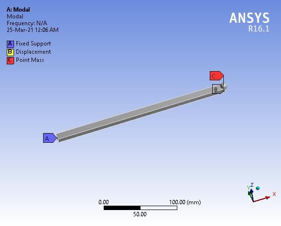
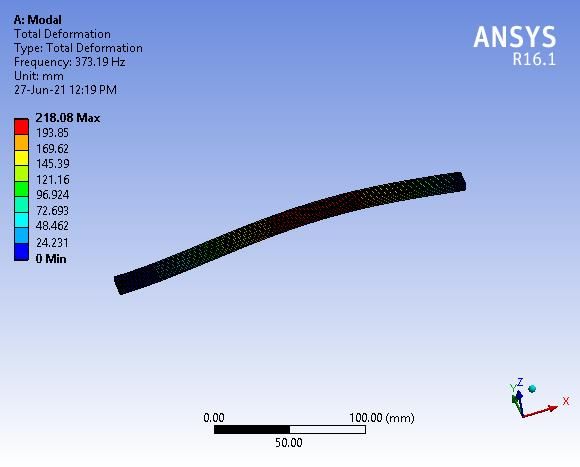
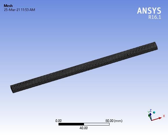
Published by : International Journal of Engineering Research & Technology (IJERT)
http://www.ijert.org ISSN: 2278-0181
 Vol. 10 Issue 06, June-2021

 6
 4
 βL

 2
 0
 0 0.2 0.4 0.6 0.8 1 1.2
 α

 Fig. 2. Impacts of mass attachment on the natural frequency of the first
 mode.
 7.5
 7
βL

 6.5
 6 Fig. 6. Mesh model
 0 0.2 0.4 0.6 0.8 1 1.2
 α
Fig. 3. Impacts of mass attachment on the natural frequency of the second
 mode.

 10.5
 10
βL

 9.5
 9
 8.5
 0 0.2 0.4 0.6 0.8 1 1.2
 α

 Fig. 4. Impacts of mass attachment on the natural frequency of the third
 mode.

 3. NUMERICAL SOLUTION
 Modal analysis module of ANSYS workbench software
 Fig. 7. Mode Shape
has been used for numerical modal analysis of a beam-
mass system. A prismatic beam model (Fig. 5) of Table 2. Vibrational frequencies of a propped cantilever beam-mass
dimension 240×12×6 mm has been developed by the system for Mode I.
design modular of ANSYS. The appropriate boundary SI. No. α Mode I
conditions are imposed to make the beam model propped ANSYS MATLAB
cantilever. A point mass of 23 gm is attached at the desired 1 0.1 371.94 371.92
 2 0.2 354.74 354.78
location on the beam. The major assumption of finite 3 0.3 317.87 317.86
element method is to discretized continuous structure in 4 0.4 283.26 283.19
finite number of elements. Now the model has been 5 0.5 262.69 262.66
discretized (Fig. 6) with Hex20 element, the total elements 6 0.6 257.48 257.48
and nodes number are 10000 and 49581 respectively. 7 0.7 268.61 268.71
 8 0.8 299.28 299.51
Finally, the natural frequencies (Hz) of a propped
 9 0.9 346.62 347.04
cantilever beam with an attached point mass at multiple 10 1 373.19 373.57
desirable locations are obtained in different bending modes.
The results have obtained from an analytical and numerical Table 3. Vibrational frequencies of a propped cantilever beam-mass
approach, which has been compared in Table 2, 3 and 4. system for Mode II.
 SI. No. α Mode II
 ANSYS MATLAB
 1 0.1 1154.00 1163.48
 2 0.2 939.58 948.40
 3 0.3 890.08 896.64
 4 0.4 987.22 994.79
 5 0.5 1152.40 1162.41
 6 0.6 1175.80 1184.83
 7 0.7 1034.40 1040.87
 8 0.8 939.55 945.46
 9 0.9 1003.30 1013.29
 10 1 1200.00 1210.59

 Fig. 5. Beam model

IJERTV10IS060395 www.ijert.org 884
 (This work is licensed under a Creative Commons Attribution 4.0 International License.)
Published by : International Journal of Engineering Research & Technology (IJERT)
http://www.ijert.org ISSN: 2278-0181
 Vol. 10 Issue 06, June-2021

 Table 4. Vibrational frequencies of a propped cantilever beam-mass
 system for Mode III.
 SI. No. α Mode III
 ANSYS MATLAB
 1 0.1 2112.90 2197.53
 2 0.2 1937.60 1978.71
 3 0.3 2235.90 2280.49
 4 0.4 2459.20 2514.36
 5 0.5 2099.80 2139.82
 6 0.6 2147.40 2193.75
 7 0.7 2464.40 2522.56
 8 0.8 2189.20 2229.12
 9 0.9 2001.10 2047.61
 10 1 2326.10 2525.87

 4. CONCLUSIONS
 The effects of a point mass on the frequencies of a
propped cantilever beam are investigated. For the first three
fundamental frequencies, a single point mass is placed at
ten evenly spaced different positions on the beam, and its
influence on frequencies is plotted. It is found that the
vibrational frequency of this beam is influenced by the
point mass location and its magnitude. The addition of
point mass reduces the natural frequencies of this beam but,
if the mass is placed at a node of the modes then its
frequencies do not change. The node positions for Mode II
and Mode III are = 0.5 and = 0.333, 0.667
respectively. The simulated results of the numerical
approach are similar to analytical results.

 REFERENCES
[1] S.S Rao,‘‘ Mechanical Vibration’’, Pearson Education, Inc.,
 publishing as Prentice Hall, 2011.
[2] K. H. Low‚‘‘A comparative study of the eigenvalue solutions for
 mass-loaded beams under classical boundary conditions’’,
 International Journal of Mechanical Sciences, Vol. 43, 2001, p. 237-
 244.
[3] V. Mermertas, H. Erol‚‘‘Effect of mass attachment on the free
 vibration of cracked beam’’, 8th International Congress on Sound
 and Vibration, Hong Kong, China, 2001, p. 2803-2810.
[4] S. Naguleswaran,‘‘Transverse vibrations of an Euler–Bernoulli
 uniform beam carrying two particles in-span’’, International Journal
 of Mechanical Sciences, Vol. 43, 2001, p. 2737-2752.
[5] H. R. Öz, E. Özkaya,‘‘Natural frequencies of beam-mass systems in
 the transverse motion for different end conditions’’, Mathematical
 and Computational Application, Vol. 10, Issue 3, 2005, p. 367-369.
[6] M. S. Kotambkar,‘‘Effect of mass attachment on natural frequency
 of free-free beam’’, International Journal of Advanced Engineering
 Research and Studies, 2014, p. 102-105.
[7] S. W. Prashant, V. N. Chougule, A.C. Mitra,‘‘Investigation on
 modal parameters of rectangular cantilever beam using experimental
 modal analysis’’, Materials Today Processdings, Vol. 2, Issue 4-5,
 2015, p. 2121-2130.
[8] A. Yadav, N. K. Singh,‘‘Effects of accelerometer mass on natural
 frequency of a magnesium alloy cantilever beam’’,
 Vibroengineering Procedia, Vol. 29, p. 207-212.
[9] A. Yadav, N. K. Singh,‘‘Investigation for Accelerometer Mass
 Effects on Natural Frequency of Magnesium Alloy Simply
 Supported Beam’’, Materials Today Proceedings, Vol. 28, 2020, p.
 2561-2565.
[10] O.Cakar, K. Y. Sanliturk,‘‘Elimination of transducer mass loading
 effects from frequency response functions’’, Mechanical Systems
 and Signal Processing, Vol. 19, 2005, p. 87-104.
[11] Jun Ren, Jun Wang, Shusheng Bi,‘‘Correction of Transducers Mass
 Effects from the Measured FRFs in Hammer Impact Testing’’,
 Shock and Vibration, Vol. 2017, 2017, p. 1-10.

IJERTV10IS060395 www.ijert.org 885
 (This work is licensed under a Creative Commons Attribution 4.0 International License.)
You can also read