THE QV-LIFT PROJECT: A GROUND SEGMENT FOR THE FUTURE
←
→
Page content transcription
If your browser does not render page correctly, please read the page content below
THE QV-LIFT PROJECT: A GROUND SEGMENT FOR THE FUTURE
Q/V BAND SATELLITE SYSTEMS.
G. Amendola (1), L. Boccia(1 , F. Greco (1), E. Arnieri (1), C. Riva (2) , L.
Luini (2), R. Nebuloni (3), G. Codispoti(4), G. Parca (4), G. Valente (4), G.
Goussetis(5), S. Kosmopoulos(5), M. Siegler(6), R.Martin (7),J.Moron(7), R.
Eleuteri(8), M. Bergmann(8), F.Massaro(9), R.Campo(9), F.Vitobello(10)
(1) CNIT-Università della Calabria (I), (2) CNIT- Politecnico di Milano(I),
(3) IEIIT/CNR (I), (4) ASI – Agenzia Spaziale Italiana (I), (5) Heriot Watt
University (UK), (4) ERZIA (S), (6) Ommic (F), (7) Skytech (I), (8)Eutelsat
(F), (9) European Commission
g.amendola@dimes.unical.it
Abstract
This paper presents a summary of the design of the Q/V band Ground Segment
currently under development in the framework of the project: “Q/V band earth
segment LInk for Future high Throughput space systems” (QV-LIFT -
www.qvlift.eu), that has recently been funded in the framework of the EU
program Horizon 2020. The project is focusing on the development of up to date
hardware and software technologies for the Ground Segment of the future Q/V
band terabit Satcom infrastructure. In the following, a description of the system
and an account of the developments related to the RF systems are presented.
Index Terms Q/V band terabit Satcom infrastructure
I. INTRODUCTION
The European Commission defined in its Digital Agenda that all
European households shall have access to internet connections of more
than 30 Mbps from 2020 onwards , so the volume of digital data
communications are expected to double by 2020 [1]. This calls for a
dramatic improvement in the satellite communication technologies as
they are a fundamental part of the global communication
infrastructure. In order to provide the necessary “Terabit connectivity”,
an evolution to “beyond Ka-band frequencies” is necessary. In fact, the
future High Throughput Satellite (HTS) systems will move up to Q and V
bands (around 40 GHz for downlink and 50 GHz for uplink) since they
offer larger bandwidth availability for the feeder links and the
opportunity to dedicate the Ka-band to user links where revenues are
generated. Moreover, Q/V-band offers attractive bandwidth for specific
segments requiring high data rates such as aeronautical in-flight
services. The QV-LIFT project started on November 16th 2016 and it
will last for about three years developing hardware and software
building blocks and integrating them in a Q/V band SatCom system.
To do this, the project will integrate the Aldo Paraboni Q/V band
payload host by Alphasat which will be used to set up both feeder and
user links. In this paper a description of the QV-LIFT Ground Segment
and an account of the developments related to the RF building blocks
are presented.
1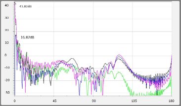
II. THE QV-LIFT GROUND SEGMENT
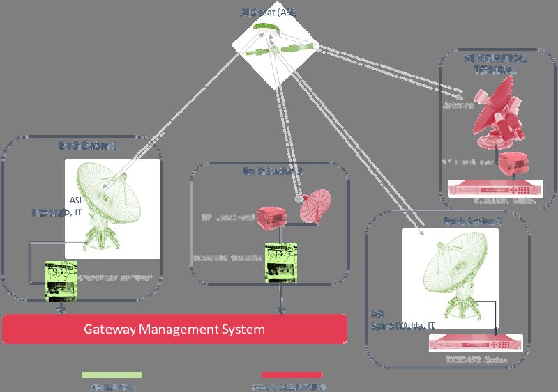
In Fig.1 is shown the overall QV-LIFT system. It is built around the Aldo
Paraboni QV band payload on board of Alphasat, developed by the
Italian Space Agency (ASI) and currently in operation. The QV-LIFT
ground segment includes two already operational Earth Stations, owned
and operated by ASI , Earth station 1, located in Tito Scalo (Italy), and
Earth Station 3, located in Spino d’Adda (Italy). A further Q/V band
ground station (Earth Station 2) and a Q/V band Aeronautical Terminal
are also included in the system and are both currently in development.
The Earth Station and the terminal will make use of a Block Up
Converters based on a power combined GaN MMICs, and high efficiency
antennas developed in the project. Also shown in Fig. 1, is the Gateway
Management System (GMS) which takes in charge the network control
functions needed to support smart handover of communications
between multiple gateway nodes (smart gateway).
FIG. 1 The QV-LIFT System
III. QV-LIFT RF DEVELOPMENTS
The QV-LIFT Ground System includes existing and operational earth
stations available with the Italian Space Agency (ASI) and newly built
systems. For the new systems, the consortium is currently developing
the following major building blocks: V band MMIC amplifier, V band
power combining SSPA (Solid State Power Amplifier), V band BUC
(Block Up Converter), Q band LNB (Low Noise Block down converter),
Q/V band (RX/TX) antennas for mobile terminals, Q/V band (RX/TX)
antenna for fixed station, Tracking and pointing systems for the mobile
and fixed antennas. As it will be detailed in the following sections, due
to the high performance required and to the high frequency of
operation, up to date technologies are needed to realize the previous
components. As an example, MMIC are based on the recently delivered
OMMIC GaN technology and they are power combined in a metallic
2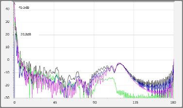
waveguide divider/combiner to provide a high power SSPA. The LNB is
based on a low noise GaAs LNA produced by OMMIC . The antenna for
the mobile terminal is an Axially Displaced Gregorian reflector with a
corrugated feed. This arrangement aims at an aperture efficiency larger
than 70% which ensures good performance in both uplink and
downlink. The fixed earth station is based on an Axially Displaced
reflector with a 1.5m diameter. In the following the involved components
will be described giving details of specifications and showing the
intermediate results available.
a. SSPA, BUC AND LNB
The SSPA is based on a MMIC GaN amplifier currently in development.
The MMIC is developed in GaN technology by OMMIC. The MMIC specs
are: Bandwidth 47.2-50.2GHz; Output Power P2dB 37 dBm (5W);
Output Power PSat 39dBm (8W); Gain>16dB; Gain Flatness +-
1.5dB; PAE 20%.
The MMIC is realized with the Ommic D01GH – 100nm. Simulated
results for Gain, Output Power, Power Added Efficiency are shown in
fig. 2 for three compression levels (1dB, 2dB, 3dB).
FIG. 2 Simulated Output Parameter of the V band GaN MMIC amplifier
under development
4 MMICs will be power combined in waveguide to reach the power level
needed by the BUC. The power dividing and combined structure is
based on 4X1 (1X4) metallic waveguide T magic with low insertion loss.
The power combining/dividing structure is designed to cover the
bandwidth from 46.5GHz to 49.5GHz.
The BUC specifications are : Input frequency 1.5 GHz; Bandwidth
500 MHz; Output frequency 46.5 – 49.5 GHz; Output power 15 W
(41.7 dBm); Gain 40 - 60 dB; S11, S22one needs antennas with G/T > 14dB/K and EIRP > 56 dBW.
Considering antennas with diameters 45cm and 60 cm and the BUC
and the LNB presented in the previous section, one finds that antenna
needs to have 70% aperture efficiency. These performances may be
reached with axially displaced reflectors which can maintain very good
performance on a large frequency band.
In Fig. 3 are shown the radiation diagram of the 45 cm antenna at
37.5GHz (RX) and 48.5 GHz (TX). Also indicated is the maximum gain
achieved which is 43.82 dB in RX and 45.5 dB in TX which correspond
to an aperture efficiency close to 80%. The antenna is able to cover
from 37GHz to 50 GHz with a good match. Similar results are achieved
for the 60 cm antenna which shows 45.9 dB in RX and 47.7 dB in TX.
The 1.5 m antenna is currently under development but preliminary
results show an aperture efficiency of 60% which is already enough to
close the link budget thanks to the large antenna size.
(a) (b)
Fig. 3. Radiation diagram of the 45cm mobile terminal antenna at 37.5GHz (a)
and 48GHz (b)
IV. CONCLUSION
The QV-LIFT project, funded by EU in the framework of the H2020
program, aims at realizing the software and hardware building blocks
for the Ground Segment of the future Q/V band satellite links. In this
paper we have presented a short description of the system under
development and the characteristics of some of the RF blocks. A more
detailed account of the system and the most recent results will be given
in the course of the presentation.
REFERENCES
[1] www.qvlift.eu
[2] Communication from the Commission to the European Parliament, the
Council, the European Economic and Social Committee and the Committee of
the Regions, “Connectivity for a Competitive Digital Single Market – Towards a
European Gigabit Society”, COM(2016) 587 final, Brussels, 14/09/2016.
[3] F.Massaro et al. “QV-LIFT Project: Using the Q/V Band Aldo Paraboni
Demonstration Payload for Validating Future Satellite Systems”, 23rd Ka and
Broadband Communications Conference, Trieste, Italy, October 16 th-19th,
2017.
[4] QV-LIFT project, D2.3 System Analysis and Requirements, Confidential,
qv-lift_d2.3_v1.0.
4You can also read