Use Your Tower as a Dual-Band DX Antenna for 75/80 and 160 Meters - NYU Wireless
←
→
Page content transcription
If your browser does not render page correctly, please read the page content below

Use Your Tower as a Dual-Band DX Antenna
                     for 75/80 and 160 Meters
                                       Theodore (Ted) S. Rappaport, N9NB
                                                      and
                                          James (Jim) Parnell, W5JAW
                                                    http://tinyurl.com/N9NB-QST

                                                    Dayton Hamvention
                                                  Antenna Forum by K3LR
                                                   Friday May 17, 2019
This work was published in QST Magazine,: T. S. Rappaport, J. Parnell, “Use your tower as a Dual-Band DX Antenna,” QST Magazine, Vol. 103, No. 5,
May 2019, pp. 41-45. Some graphics contained in this presentation ©
                                                                  with
                                                                    2018permission
                                                                        NYU WIRELESSfrom QST. The QR Code provides a reprint of the 1ARRL QST article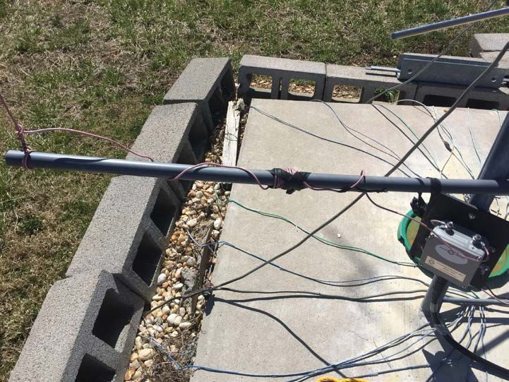
Outline of Talk
• Motivation for this Antenna

• Basic Concepts of a Dual Band vertical antenna

• Computer Modeling and Novel Design

• Construction of Antenna

• Tuning and real-world implementation

• Results and Conclusion
                                                   2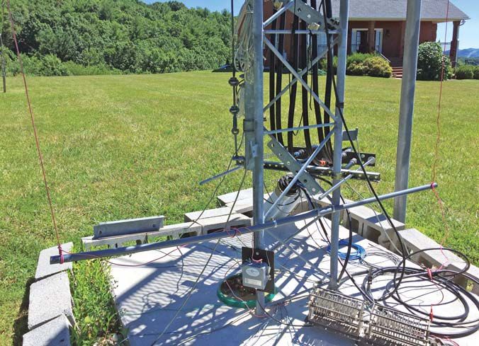
Motivation for this Antenna
N9NB in Riner VA is on a ridge – a very windy

                                                3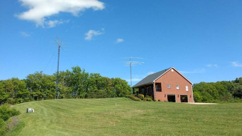
Motivation for this Antenna

                              4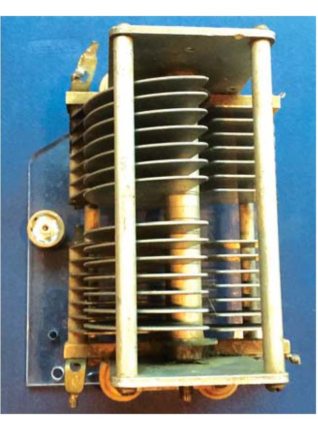
Motivation for this Antenna
• Very windy! The 160 m Inverted-L tied to tree came down often

•   ~ 250’ - 300’ ground slope from JA to EU

• Two towers and trees only 65’ – 80’ tall

•   80 m and 160 m dipoles did not perform well– too low?

•   30 ground radials (~ 50’ each) installed for eventual vertical use.

• Needed a low-maintenance, low-profile performer
                                                                          5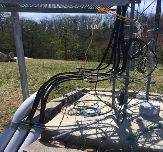
Motivation for this Antenna
    Past 160 m solutions motivated me to solve the wind and
    performance problems at the N9NB ridge top location:

• A low-profile 160 m antenna in college for my apartment:
  “T. S. Rappaport, “160 meter transmission line antenna,” Ham
   Radio Magazine, May 1985, pp. 87-91

•   K9RS achieved gain using a parasitic tower on his 4-square:
    R. Sokola, T. S. Rappaport, “Multi-element low band vertical
    arrays – approaches for small and other lots, ” 2008 Dayton
    Antenna Forum
                                                                   6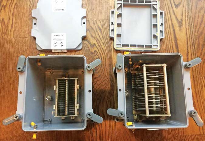
Motivation for this Antenna

    One day at lunch in Austin, Texas in November 2017………..

• W5JAW had modeled N3BB’s tower for a 160 m shunt fed vertical

•   I had been trying to figure out a single-feed dual band vertical for years……
     • Investigated parasitic 80 m verticals next to 160 m but always 1 - 3 dB loss

• Inspiration struck as W5JAW and I tried different EZNEC concepts

• For 160 m shunt feed, a parallel wire located a few feet away can work on 80m
   • Much lower impedance (about 12 ohms)
   • Only 0.2- 0.5 dB loss from modeled ideal vertical performance, need 1:4 unun
                                                                                      7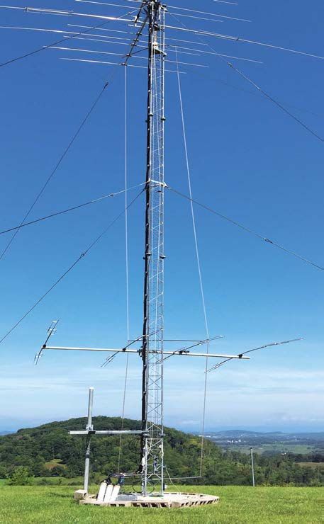
Basic Concepts of Multi-Band Antenna
• Single feedline for multiple bands is convenient and cost-efficient

• Some multi-band dipoles do not require any traps or tuners or switches

• Resonance for one band should not be “bothered” by the other bands

• I had been using a single feed dual band dipole for 80/160 m at N9NB

• 80 m dipole is electrically short, high Z (cap) in parallel to 160 m feed

• 160 m dipole has high Z (resistive) in parallel to 80 m feed

                                                                              8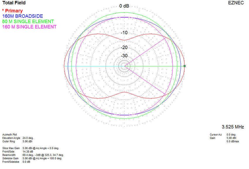
Basic Concepts of Fan Dipole Antenna

                                       9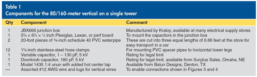
Computer Modeling and Novel Design
• First step: Find resonance of tower – used EZNEC for base current feed

• Once we knew the tower could be shunt fed, 160 m was solved (ON4UN)

• Second step: Found proper spacing and length of parallel 80 m vertical wire

• Third step: Realized 80 m vertical used a 12-15 ohm feed impedance (1:4)

• Single feed with standard 1:4 Unun (80 m) and parallel “hot center” for 160 m

• Fourth step: Realized sensitivity at base of tower on 80 m – can tune 75/80!

• Fifth step: Build a single vertical and a 2 el phased array – have fun!
                                                                                 10
Computer Modeling and Novel Design
80 m 160 m
vertical shunt
Current
source (f)
11Construction of the antenna
Graphics Courtesy QST Magazine, T.S. Rappaport,
J. Parnell, “Use your tower as a dual band, low band DX
antenna, QST, May 2019, pp. 41-45 12Construction of the antenna
W5JAW Center Insulated driven element
Tapped Toroid at top of tower must be
Coil Solution for center shunted to tower
insulated to prevent 160 /80 m
currents on balun/coax
driven element (do this for all top yagis)
at N3BB
Hi Z center-tapped
toroid coil shunts
Use this if the driven elements
You have a to tower, bringing all
currents onto tower
Yagi with and not on yagi
insulated balun or yagi coax
driven
element 13Construction of the antenna
• Center-tapped toroid coil w/balun: grounds insulated driven element
• W5JAW’s solution eliminates 160 m currents on top yagi balun/coax
Added center tapped
Core: stack of two
toroid in parallel with Shunt to
Amidon FT-114A-61
stock yagi balun: the tower via
cores w/ties.
center tap shunts boom or
Currents in two
mast
insulated driven halves of driven
elements to tower elements are equal
and in phase, giving
Zero vector sum flux
Windings of center- in the toroid core,
tapped toroid goes and Low Z to the
across insulated top center tap. End to
yagi driven elements, end Z diff. for feed
use this idea for all line is 4KΩ, no
impact on 14-30 MHz
driven elements at top SWR
of your tower
14Construction of the antenna
• Antenna parts cost less than $125 for a dual band 80/160 m vertical
Graphic Courtesy QST Magazine, T.S. Rappaport, J. Parnell, “Use your tower as a
dual band, low band DX antenna, QST, Vol. 103, No. 5, May 2019, pp. 41-45
15Construction of the antenna
• Gamma Match capacitor construction
16Construction of the antenna
17Tuning and Implementation
• First: Tune 160 M Gamma match height and Cap with 80 m/unun connected
• Second: Determine 80 m wire height and spacing, special care for base spacing
• Third: using PVC pipe as a core, a tight coil lowers 80 m resonant freq.
• Fourth: Moving 80 m wire closer to tower and uncoiling raises the freq.
3525 kHz
3725 kHz
18Tuning and Implementation
• SWR is excellent over 100 kHz range on both bands
• Easy to move between 3525 and 3725 khz resonance w/coil base and tie rope
• No tuners, traps, or moving parts!
Graphics Courtesy QST Magazine
T.S. Rappaport, J. Parnell, “Use your tower as a dual band, low band DX antenna, QST, May 2019, pp. 41-45
19Practical Implementation (no EZNEC)
• First step: ON4UN: estimate or measure your tower resonance for 160 shunt
• Second step: If insulated top yagi(s), install parallel center-tap toroid(s) to
ensure proper vertical performance, and protect hi-band yagi(s) balun/coax
• Third step: Install single band 160 m shunt fed vertical to validate performance
• Fourth step: Install single coax w/1:4 Unun, 80 m wire 3’ from tower || 160 shunt
• Fifth step: Experiment with length of 80 m wire and spacing from tower, and
spacing length (and coil of wire) at base of tower on 80 m – can tune 75/80
• Sixth step: Confirm both 160 and 80/75 provide resonance, HAVE FUN!
20Tuning and Implementation
• For a Two Element dual-band phased array, use two identical vertical towers
• Identical 125’ coax runs to each of the two towers – equal phase feeds
• Using a stack match in shack, I can select N, S, or BOTH
• N drives the N vertical for gain to the N-NW using the south tower as reflector
• S drives the S vertical for gain to the S-SE using the north tower as reflector
• Exploits parasitic reflector as in K9RS 4-square (2008 Dayton Antenna forum)
• BOTH drives each vertical: broadside 2 element phased array to NE and SW
21Tuning and Implementation
• 2 Element Phased Array gain > single element: 1.1 dB (160) and 3.8 dB (80)
• 2 Element design: Half wave spacing on 80 m, Quarter wave spacing on 160 m
Best elevation angle depends on ground cond. (EZNEC and
ON4UN): Model shows 24 deg. for 160 m and 25 deg. for 80 m.
More radials will improve single element gains!
160m Single Array Gain
2.8 dBi 3.95 dBi 1.15 dB
80m 1.28 dBi 5.06 dBi 3.78 dB
22Results and Conclusion
Does it work??? I consistently break pile ups and work what is heard w/LP
• #3 World Low Power Stew Perry Top Band Challenge December 2018
• (Low Power World QSO leader, did not use any RX antenna other than the vertical!)
• #1 US Low Power 2019 ARRL CW DX (preliminary)
• #1 North America Low Power 2019 Russian DX Contest (preliminary)
• #1 North America Low Power 2019 CQWPX SSB (preliminary)
YES! IT WORKS !!! ……BUT WAIT, there’s MORE……..
23Results and Conclusion
• Amazingly, the antenna tunes well on almost every band: 160-6 m!
• EVEN WARC BANDS and 6 m without a tuner! Who would have guessed?
• Discovered by remote operation with limited antennas connected
• Worst VSWR was 5:1 on 40 m and 15 m, other bands did not need a tuner!
• Unexpected benefit! No telling what the patterns are – but I can work DX!
24Results and Conclusion
CONCLUSION:
• I no longer use dipoles. The tower verticals are my only 80/160 m TX Ants.
• These verticals are easy to make, easy to maintain, and really work well!
• They require no tuners, traps or switches for dual band 80/160 m operation
• Adding more ground radials will improve the gain even more
• TRY IT, YOU’LL LIKE IT!
25Results and Conclusion
THANK YOU !
73
de
N9NB and W5JAW
Use this QR Code for a preprint of May 2019 QST article
about this antenna: http://tinyurl.com/N9NB-QST
26You can also read