LTE-Advanced Technology Introduction White Paper
←
→
Page content transcription
If your browser does not render page correctly, please read the page content below
LTE-Advanced
Technology Introduction
White Paper

Although the commercialization of LTE
technology began in end 2009, the
technology is being enhanced in order to
meet ITU-Advanced requirements. This
white paper summarizes these necessary
improvements specified in 3GPP Release
10, which are also known as LTE-
Advanced.

                                           LTE-Advanced

                                                          M. Kottkamp, A. Roessler, J. Schlienz
                                                                          08.2012-1MA169_3E
Table of Contents
Table of Contents
1 Introduction ............................................................................ 4
2 LTE-Advanced requirements ................................................ 6
3 Technology Components of LTE-Advanced........................ 8
3.1 UE categories for LTE-Advanced ...............................................................8
3.2 Band aggregation .........................................................................................9
3.2.1 Frequency deployment scenarios ............................................................11
3.2.2 UE bandwidth classes ...............................................................................13
3.2.3 Cross carrier scheduling ...........................................................................15
3.2.4 HARQ ACK/NACK procedure for multiple cells, PUCCH format 3 ........17
3.2.5 User plane ...................................................................................................18
3.2.6 Control plane ..............................................................................................19
3.3 Enhanced multiple antenna technologies ...............................................19
3.3.1 Downlink......................................................................................................21
3.3.1.1 Layer mapping for downlink spatial multiplexing...................................21
3.3.1.2 Scheduling of downlink resources, Transmission Mode 9 (TM9) .........22
3.3.1.3 Downlink reference signal structure ........................................................23
3.3.2 Uplink...........................................................................................................24
3.3.2.1 Layer mapping for uplink spatial multiplexing........................................24
3.3.2.2 Scheduling of uplink resources, Transmission Mode 2 (TM2) ..............27
3.4 Enhanced uplink transmission scheme...................................................29
3.4.1 Simultaneous PUCCH and PUSCH transmission ...................................29
3.4.2 Multi-cluster transmission.........................................................................30
3.4.2.1 Scheduling of multi-clustered transmission ...........................................30
3.5 Enhanced Inter-cell Interference Coordination (eICIC) ..........................31
3.6 Relaying.......................................................................................................35
3.6.1 Air Interface.................................................................................................35
3.6.2 Attachment of a Relay Node to the Network ...........................................36
4 Conclusion............................................................................ 37
5 Appendix............................................................................... 38
5.1 LTE-Advanced frequency bands ..............................................................38
1MA169_3E Rohde & Schwarz LTE Advanced Technology Introduction 2Table of Contents
6 Literature............................................................................... 39
7 Additional Information......................................................... 40
1MA169_3E Rohde & Schwarz LTE Advanced Technology Introduction 3Introduction
1 Introduction
LTE (Long Term Evolution) standardization within the 3GPP (3rd Generation
Partnership Project) has reached a mature state. Changes in the specification are
limited to corrections and bug fixes. Since end 2009, LTE mobile communication
systems are deployed as a natural evolution of GSM (Global system for mobile
communications) and UMTS (Universal Mobile Telecommunications System).
The ITU (International Telecommunication Union) coined the term IMT-Advanced to
identify mobile systems whose capabilities go beyond those of IMT 2000 (International
Mobile Telecommunications). Specifically data rate requirements are increased. In
order to support advanced services and applications 100Mbps for high and 1Gbps for
low mobility scenarios must be realized. Throughout 2009 3GPP worked on a study
with the purpose of identifying the LTE improvements required to meet IMT-Advanced
requirements. In September 2009 the 3GPP Partners made a formal submission to the
ITU proposing that LTE Release 10 & beyond (LTE-Advanced) should be evaluated as
a candidate for IMT-Advanced. In October 2010 LTE-Advanced successfully
completed the evaluation process in ITU-R complying with or exceeding the IMT-
Advanced requirements and thus became an acknowledged 4G technology. Beyond
achieving technical requirements, a major reason for aligning LTE with the call for IMT-
Advanced is that IMT conformant systems will be candidates for future new spectrum
bands that are still to be identified. This ensures that today’s deployed LTE mobile
networks provide an evolutionary path towards many years of commercial operation.
This white paper summarizes LTE-Advanced features based on [3] and finally
specified in 3GPP RAN specification.
Section 2 outlines the IMT-Advanced requirements and section 3 summarizes the main
technology components (see Figure 1). Section 3.1 introduces new UE categories
common to all LTE-Advanced technology components, followed by
section 3.2 on band aggregation,
section 3.3 on enhanced multiple input / output (MIMO) antenna technologies in
both downlink and uplink direction,
section 3.4 introducing enhancements of the uplink transmission scheme,
section 3.5 describing enhanced inter-cell interference coordination techniques,
section 3.6 on the application of intelligent relay nodes.
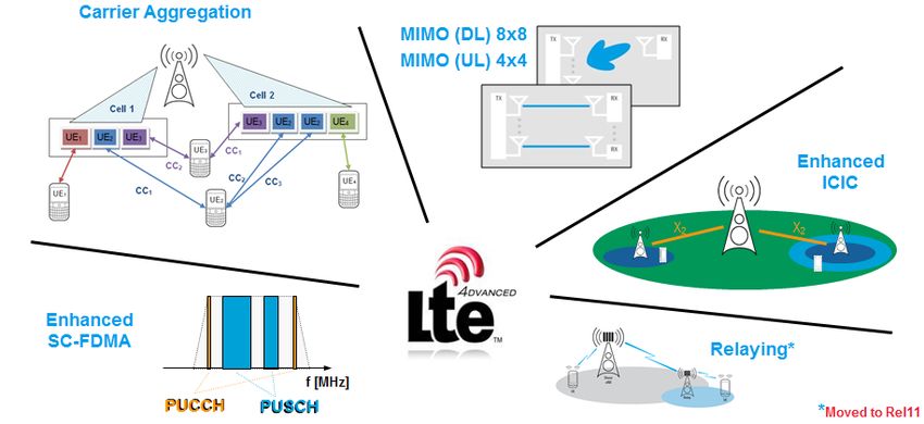
Figure 1: Main LTE-Advanced technology components (overview)
1MA169_3E Rohde & Schwarz LTE Advanced Technology Introduction 4Introduction
Section 4 concludes this white paper. The appendix in section 5 and section 6 provide
additional information including a summary of LTE frequency bands and literature
references.
Note that this white paper assumes basic knowledge of the LTE technology as
specified in 3GPP Release 8. An easy-to-read LTE technology introduction can be
found in [1].
1MA169_3E Rohde & Schwarz LTE Advanced Technology Introduction 5LTE-Advanced requirements
2 LTE-Advanced requirements
Based on the ITU requirements for IMT-Advanced systems, 3GPP created a technical
report summarizing LTE-Advanced requirements in [4]. The IMT-Advanced key
features delineated in the circular letter inviting candidate radio interface technologies
are given below:
a high degree of commonality of functionality worldwide while retaining the
flexibility to support a wide range of services and applications in a cost efficient
manner;
compatibility of services within IMT and with fixed networks;
capability of interworking with other radio access systems;
high quality mobile services;
user equipment suitable for worldwide use;
user-friendly applications, services and equipment;
worldwide roaming capability; and
enhanced instantaneous peak data rates to support advanced services and
applications (100 Mbps for high and 1 Gbps for low mobility were established as
targets for research).
In [4] the LTE-Advanced requirements are detailed as follows. In general the above
IMT-Advanced requirements shall be met or even exceeded. Additionally all existing
LTE requirements are equally applicable to LTE-Advanced. For several categories
concrete requirements have been set.
Peak data rate
The system should target a downlink peak data rate of 1 Gbps and an uplink peak data
rate of 500 Mbps.
Latency
C-Plane: The target for transition time from idle mode (with internet protocol (IP)
address allocated) to connected mode should be less than 50 ms including the
establishment of the user plane (excluding the S1 interface transfer delay). The target
for the transition from a "dormant state" to connected mode (i.e. discontinuous
reception (DRX) sub-state in connected mode) should be less than 10 ms (excluding
the DRX delay).
U-Plane: LTE-Advanced should allow for reduced U-plane latency compared to LTE
Release 8.
Spectrum efficiency
LTE-Advanced aims to support downlink (8x8 antenna configuration) peak spectrum
efficiency of 30 bps/Hz and uplink (4x4 antenna configuration) peak spectrum
efficiency of 15 bps/Hz. Additionally average spectrum efficiency targets have been set
according to Table 1. Average spectrum efficiency is defined as the aggregate
throughput of all users (the number of correctly received bits over a certain period of
time) normalized by the overall cell bandwidth divided by the number of cells.
Antenna configuration Target [bps/Hz/cell]
Uplink 1x2 / 2x4 1.2 / 2.0
Downlink 2x2 / 4x2 / 4x4 2.4 / 2.6 / 3.7
Table 1: Targets for average spectrum efficiency
1MA169_3E Rohde & Schwarz LTE Advanced Technology Introduction 6LTE-Advanced requirements
Cell edge user throughput
LTE-Advanced should allow cell edge user throughput to be as high as possible. The
cell edge user throughput is defined as the 5% point of the cumulative density function
(CDF) of the user throughput normalized with the overall cell bandwidth. Requirements
for cell edge performance are given in Table 2 below.
Antenna configuration Target [bps/Hz/cell/user]
Uplink 1x2 / 2x4 0.04 / 0.07
Downlink 2x2 / 4x2 / 4x4 0.07 / 0.09 / 0.12
Table 2: Targets for cell edge user throughput
VoIP capacity
VoIP capacity should been improved for all antenna configurations in comparison to
LTE Release 8.
Mobility
Mobility requirements have been formulated in comparison to LTE Release 8. The
system shall support mobility across the cellular network for various mobile speeds up
to 350km/h (or even up to 500km/h depending on the frequency band). In comparison
to LTE Release 8, the system performance shall be enhanced for 0 up to 10 km/h.
Spectrum flexibility
The initial identified frequency bands in addition to the already allocated bands in LTE
Release 8 (see section 5.1) are as follows:
450 470 MHz band,
698 862 MHz band,
790 862 MHz band,
2.3 2.4 GHz band,
3.4 4.2 GHz band, and
4.4-4.99 GHz band.
LTE-Advanced shall operate in spectrum allocations of different sizes including wider
spectrum allocations than those of LTE Release 8. The main focus for bandwidth
solutions wider than 20MHz should be on consecutive spectrum. However aggregation
of the spectrum for LTE-Advanced should take into account reasonable user
equipment (UE) complexity. Frequency division duplex (FDD) and time division duplex
(TDD) should be supported for existing paired and unpaired frequency bands,
respectively.
1MA169_3E Rohde & Schwarz LTE Advanced Technology Introduction 7Technology Components of LTE-Advanced
UE categories for LTE-Advanced
3 Technology Components of LTE-Advanced
3.1 UE categories for LTE-Advanced
Independent from the LTE-Advanced technology components, new UE categories 6, 7
and 8 are added into LTE Release 10 according to Table 3 and Table 4.
UE Maximum number of Maximum number of Total number Maximum number
Category DL-SCH transport bits of a DL-SCH of soft of supported
block bits received transport block channel bits layers for spatial
within a TTI received within a TTI multiplexing in DL
… … … … …
149776 (4 layers)
6 301504 3654144 2 or 4
75376 (2 layers)
149776 (4 layers)
7 301504 3654144 2 or 4
75376 (2 layers)
8 2998560 299856 35982720 8
Table 3: New downlink UE categories [11]
UE Maximum number of Maximum number of bits Support for Total layer 2
Category DL-SCH transport of an UL-SCH transport 64QAM in UL buffer size
block bits received block transmitted within [bytes]
within a TTI a TTI
… … … … …
6 51024 51024 No 3 300 000
7 102048 51024 No 3 800 000
8 1497760 149776 Yes 42 200 000
Table 4: New uplink UE categories [11]
These categories describe to a certain extend the devices capabilities. For instance
categories 6 and 7 support MIMO 2x2 and/or 4x4 and go up to data rates of 300 Mbps.
Whereas category 8 is the highest category, supporting 8x8 MIMO leading to a peak
data rate of 3 Gbps, if the maximum of five component carriers are aggregated. Uplink
category 8 leads to 1.5 Gbps data rate using 4x4 MIMO and 64QAM modulation. Note
that this UE category significantly exceeds the IMT-Advanced requirements. The UE
category is only an indication of the user devices capabilities. It is used as kind of an
upper bound for achievable data rates. Much more detailed information on the UE
capabilities is signaled to the network on RRC layer. The initial attach procedure is
unchanged compared with LTE Release 8 (see Figure 2). After EPS bearer setup and
during the UE capability transfer, the device identifies itself as LTE Release10 capable
by providing additional information on top of the “standard” LTE Release 8 capabilities.
These more detailed capabilities refer to the LTE-Advanced features described in the
following sections of this white paper as well as regarding support for more general
capabilities, i.e. support of specific frequency bands (see Figure 3).
1MA169_3E Rohde & Schwarz LTE Advanced Technology Introduction 8Technology Components of LTE-Advanced
Band aggregation
Figure 2: LTE attach procedure
Figure 3: UE-EUTRA capability information element [12]
3.2 Band aggregation
One straight forward possibility to reach high data rates requirements is to aggregate
multiple LTE carrier (see Figure 4). Two or more component carriers (CC) are
aggregated in order to support wider transmission bandwidths up to 100MHz. Each
component carrier has a maximum of 110 resource blocks (RB). However initial LTE-
Advanced (3GPP Release 10) deployments will be limited to the use of maximum two
component carrier, i.e. the initial maximum DL/UL bandwidth will be 40MHz. In fact
even less bandwidth will initially be used, because the band aggregation feature will
allow a more flexible use of diverse spectrum allocations available in an operator
network. Existing band allocations to an individual operator often consists of spectrum
fractions in various frequency bands. Therefore offering the possibility to aggregate
e.g. 5MHz in one frequency band with 10 MHz in a different frequency band is equally
important than achieving highest data rates.
1MA169_3E Rohde & Schwarz LTE Advanced Technology Introduction 9Technology Components of LTE-Advanced
Band aggregation
Cell 2
Cell 1
UE3 UE2 UE2 UE4
UE1 UE2 UE3
UE3 CC1
CC2
CC2 CC3 UE4
UE1 CC1
UE2
Figure 4: LTE-Advanced maximum bandwidth in contiguous deployment
The component carrier set is UE specific, whereas registration with the network is
always taking place on the primary component carrier (PCC). Additional bandwidth is
provided by secondary component carriers (SCC) with a maximum of four SCCs. In
downlink direction PDCCH allocation on SCC is optional whereas in uplink direction
only the PCC carries PUCCH (see Figure 5).
Figure 5: Channel allocation on PCC and SCC
On the radio link control (RLC) layer there is only one connection per UE independent
of the number of component carriers assigned. Multiple CCs are handled on the
Medium Access Control (MAC) layer, i.e. in the scheduler of the eNodeB. There are
separate HARQ transmissions and acknowledgements for each CC. Common timing
control for all UL component carriers (one timing advance (TA) command) is applied,
but individual power control for each carrier (TPC commands) is realized. Handover is
only applicable for the PCC as well as RACH procedures are naturally only executed
on the PCC. The UE provides individual channel state information (CSI) reporting for
each individual CC. In LTE FDD more downlink CCs may be allocated than in uplink in
order to address asymmetric traffic requirements. Note that for TD-LTE all component
carriers have the same DL/UL time slot configuration, since asymmetric traffic may be
addressed by the appropriate number of time slots in DL and UL, respectively.
Independent of the initial asymmetric aggregation of carriers, there is a need for
enhanced uplink feedback mechanisms to feed back all the information related to the
transmission and channel quality parameters. For acknowledgement/non-
acknowledgements PUCCH format 1b has been enhanced, now with channel
selection.
1MA169_3E Rohde & Schwarz LTE Advanced Technology Introduction 10Technology Components of LTE-Advanced
Band aggregation
Additionally a new PUCCH format 3 is introduced. In contrast to the existing LTE
Release 8 PUCCH formats, it is not a Zadoff-Chu sequence anymore. The new
PUCCH format is more a type of PUSCH transmission, using QPSK modulation.
Orthogonal Cover Codes are applied to transmit a large number of ACK/NACK bits, i.e.
20 bits in case of LTE TDD and 10 bits for LTE FDD (see details in [7], [8] and [9]).
This allows the transmission of ACK/NACK for up to 5 carriers assuming 2x2 MIMO is
applied to each carrier, resulting in 10 ACK/NACK bits for the two code words
eventually transmitted per component carrier. The resources to be used for PUCCH
format 3 are explicitly signaled to the user device.
In order to support legacy LTE Release 8 terminals it is required that each of the
component carriers can be configured to be a LTE Release 8 carrier. However not all
component carriers are necessarily LTE Release 8 compatible. Contiguous and non-
contiguous component carrier aggregation as well as intra-band and inter-band carrier
aggregation is supported (see Figure 6). The high degree in flexible allocations allows
addressing individual operator needs including the support of heterogeneous network
deployments (see section 3.5).
Figure 6: LTE-Advanced spectrum deployment
3.2.1 Frequency deployment scenarios
The different regions in the world have different frequency deployments of existing
technologies. Band aggregation is also used in WCDMA/HSPA networks.
Consequently a high variety of evolution scenarios exist to migrate from existing
technologies to LTE / LTE-Advanced. The interest in a high number of different band
combinations resulted into a limited number of carrier frequency scenarios specified in
RAN4 within the 3GPP Release 10 timeframe. It was agreed to work out requirements
for these limited scenarios first before adding scenarios with more practical relevance
in a release independent manner later. Note that support for frequency bands is
generally release independent. Frequency bands are added to 3GPP specifications
whenever identified. Still a UE may support a certain frequency band added in a later
3GPP Release (e.g. Release 9) even if it generally supports an earlier 3GPP Release
feature set (e.g. Release 8) only. The initial work in 3GPP RAN4 concentrated on the
following intra- and inter-band scenarios (see Table 5).
1MA169_3E Rohde & Schwarz LTE Advanced Technology Introduction 11Technology Components of LTE-Advanced
Band aggregation
Intra band CA operating bands
E-UTRA E-UTRA Uplink (UL) Downlink (DL) Duplex
CA Band Band operating band operating band Mode
CA_1 1 1920 – 1980 MHz 2110 – 2170 MHz FDD
CA_40 40 2300 – 2400 MHz 2300 – 2400 MHz TDD
Inter band CA operating bands
E-UTRA E-UTRA Uplink (UL) Downlink (DL) Duplex
CA Band Band operating band operating band Mode
1 1920 – 1980 MHz 2110 – 2170 MHz
CA_1-5 FDD
5 824 – 849 MHz 869 – 894 MHz
Table 5: Intra- and inter-band carrier aggregation focus scenarios according to 3GPP RAN4 [5]
Subsequently a fairly high number of different work items were started to work on
individual operator relevant frequency band combinations as shown in Table 6. The
rapporteur name indicates which region in the world is interested in the specific band
combination. The different frequency ranges are marked in order to provide an
illustration on the important frequency bands. Obviously for LTE using FDD mode there
is a high interest in aggregating lower frequency bands around 800 MHz with
frequency bands around 2 GHz as well as some interest in aggregating frequency
bands around 2 GHz with frequency bands around 2.6 GHz. There are two carrier
aggregation work items on LTE in TDD Mode, which are relevant for intra-band carrier
aggregation only. One single work item addresses the case of two uplink carrier
frequencies, i.e. all other do not apply carrier aggregation in uplink.
Title 700 - 900 1.5 – 1.8 – 2.6 Rapporteur
MHz 1.6 GHz 2.1 GHz GHz
Intra band carrier aggregation (2DL, 1UL)
LTE-A CA in B7 China Unicom
LTE-A CA of B38 Huawei
(TD-LTE)
LTE-A CA of Band 41 Clearwire
(TD-LTE)
LTE-A CA in B3 SK Telecom
LTE-A CA in B25 Sprint
Inter band carrier aggregation (2DL, 1UL)
LTE-A CA of B1_B 7 China Telecom
LTE-A CA of B1_B18 KDDI
LTE-A CA of B1_B19 NTT DoCoMo
LTE-A CA of B1_B 21 NTT DoCoMo
LTE-A CA of B2_B17 AT&T
LTE-A CA of B3_B5 SK Telecom
LTE-A CA of B3_B7 TeliaSonera
1MA169_3E Rohde & Schwarz LTE Advanced Technology Introduction 12Technology Components of LTE-Advanced
Band aggregation
Title 700 - 900 1.5 – 1.8 – 2.6 Rapporteur
MHz 1.6 GHz 2.1 GHz GHz
Inter band carrier aggregation (2DL, 1UL)
LTE-A CA of B3_B8 SK Telecom
LTE-A CA of B3_B20 Vodafone
LTE-A CA of B4_B5 AT&T
LTE-A CA of B4_B7 Rogers Wireless
Cox
LTE-A CA of B4_B12 Communications
LTE-A CA of B4_B13 Ericsson
LTE-A CA of B4_B17 AT&T
LTE-A CA of B5_B12 US Cellular
LTE-A CA of B5_B17 AT&T
LTE-A CA of B7_B20 Huawei
LTE-A CA of B8_B20 Vodafone
LTE-A CA of B11_B18 KDDI
Inter band carrier aggregation (2DL, 2UL)
LTE-A CA of B3_B5 SK Telecom
Table 6: Intra- and inter-band carrier aggregation scenarios with work item started in 3GPP RAN4
LTE Release 8 allows a 100 kHz frequency raster placing the LTE channel within the
operator owned bandwidth. The 15 kHz subcarrier spacing in combination with
contiguously aggregated component carriers requires a 300 kHz carrier spacing in
order to preserve the orthogonality in the downlink transmission scheme.
3.2.2 UE bandwidth classes
New UE bandwidth classes applicable to carrier aggregation are specified in [5]. Note
that 3GPP RAN4 defines the number of resource blocks in a transmission bandwidth
based on the channel bandwidth according to Table 7. I.e. in 20 MHz channel the
maximum number of resource blocks including guard band considerations is equal to
100 in contrast to a maximum of 110 resource blocks per carrier specified in 3GPP
RAN1.
Channel bandwidth
1.4 3 5 10 15 20
BWChannel [MHz]
Transmission bandwidth
6 15 25 50 75 100
configuration NRB
Table 7: Transmission bandwidth configuration NRB in E-UTRA channel bandwidths [5]
1MA169_3E Rohde & Schwarz LTE Advanced Technology Introduction 13Technology Components of LTE-Advanced
Band aggregation
For intra-band carrier aggregation parameters are specified according to Figure 7. Six
UE bandwidth classes are foreseen, whereas only three are fully specified up to now.
Bandwidth classes are defined in terms of number of resource blocks with the
aggregated transmission bandwidth and the maximum number of component carriers
supported (see Table 8).
Aggregated Channel Bandwidth,
BWchannel_CA [MHz]
Lower Edge
Aggregated Transmission Bandwidth Configuration, NRB_agg [RB]
Higher Edge
Lowest Carrier Transmission Highest Carrier Transmission
Bandwidth Configuration,
Guard Band
Guard Band
Bandwidth Configuration
NRB,low [RB] NRB high [RB]
Resource block
Foffset,low Foffset,high
Fedge,low FC,low FC,high Fedge,high
For each carrier, the center sub carrier
(corresponds to DC in baseband) is not
Figure 7: Definition of Aggregated channel bandwidth and aggregated channel bandwidth edges [5]
CA Bandwidth Aggregated Transmission Maximum
Nominal Guard Band BWGB
Class Bandwidth Configuration number of CC
A NRB,agg £ 100 1 0.05BW Channel(1)
B NRB,agg £ 100 2 FFS
C 100 < NRB,agg £ 200 2 0.05 max(BWChannel(1),BWChannel(2))
D 200 < NRB,agg £ [300] FFS FFS
E [300] < NRB,agg £ [400] FFS FFS
F [400] < NRB,agg £ [500] FFS FFS
BWChannel(1) and BWChannel(2) are channel bandwidths of two E-UTRA component carriers according to Table 7
Table 8: CA bandwidth classes and corresponding nominal guard bands
Supported bandwidth classes are indicated to the network on a per band basis
individually for each up- and downlink direction, including the support of either intra-
band (contiguous or non-contiguous) or inter-band carrier aggregation (see section
3.2). Figure 8 provides an example which terminology is used by the device to indicate
its support of carrier aggregation for a particular frequency band or band combination.
Take the intra-band non-contiguous case with CA_25A_25A as an example. It tells the
network, that this device is able to receive (or transmit) two separate carriers in
frequency band 25; each one with a maximum bandwidth of 100 RB (20 MHz). If this
device would be able to aggregate two carriers in that frequency band, but
continuously, the acronym would change to CA_25C. Bandwidth class C (see Table 8)
defines an aggregated transmission bandwidth between 100 and 200 RB, allocated to
two component carriers.
1MA169_3E Rohde & Schwarz LTE Advanced Technology Introduction 14Technology Components of LTE-Advanced
Band aggregation
contiguous non-contiguous
Intra-band CA Intra-band CA Inter-band CA
E-UTRA band number
CA_1C
1C 25A 25A
CA_25A_25A 1A 5A
CA_1A_5A
Supported bandwidth class
Figure 8: Notation of carrier aggregation support (type, frequency band, and bandwidth)
The carrier aggregation feature allows a high degree of flexibility to adapt to individual
spectrum deployments. However not all combinations are of practical relevance. For
the initial LTE Release10 carrier aggregation scenarios as shown in Table 5, the
following carrier aggregation configurations are considered:
CA Configuration / NRB_agg
CA E-UTRA Band 50RB+100RB 75RB+75RB 100RB+100RB
Configuration (10 MHz + 20 MHz) (15 MHz + 15 MHz) (20 MHz + 20 MHz)
CA_1C 1 Yes Yes
CA_40C 40 Yes Yes Yes
Table 9: Supported CC combinations per CA configuration for intra-band contiguous CA [5]
CA operating / Channel bandwidth
CA E-UTRA 1.4 MHz 3 MHz 5 MHz 10 MHz 15 MHz 20 MHz
Configuration Bands
1 Yes
CA_1A-5A
5 Yes
Table 10: Supported CC combinations per CA configuration for intra-band contiguous CA [5]
3.2.3 Cross carrier scheduling
As of LTE Release 8 each component carrier may use PDCCH to schedule resources
for an individual UE that receives multiple carriers in downlink. This scheduling method
is backward compatible to LTE Release 8. Additionally and optionally cross carrier
scheduling was introduced. This method uses the PDCCH on the PCC in order to
schedule resources on the SCCs by using the new carrier indicator field (CFI), see
Figure 9.
1MA169_3E Rohde & Schwarz LTE Advanced Technology Introduction 15Technology Components of LTE-Advanced
Band aggregation
Figure 9: Cross carrier scheduling in comparison to LTE Release 8
The motivation behind the definition of cross-carrier scheduling is to spare signaling
capacity and to enable heterogonous networks with support of load balancing for
different cell layers (see section 3.5). The PDCCH start can be configured in the time
domain by dedicated RRC signaling, i.e. an overlap of PDCCH in different cell layers
can be avoided. Note that if a component carrier is already scheduled via ONE
component carrier, it cannot be scheduled by another component carrier. In the
example in Figure 10 we have 5 component carriers and cross carrier scheduling is
activated. CC#1 schedules resources on CC#1 and #2. For that specific user device
CC#5 is not allowed to schedule any resources on CC#2.
Frequency Macro layer Pico layer
Time
Figure 10: Cross carrier scheduling for support in heterogeneous networks
In order to allow cross carrier scheduling the existing LTE Release 8 DCI format
scheme is extended. From 3GPP Release 10 onwards the downlink control information
includes a 3 bit carrier indicator field (CFI), which provides index information of that
carrier, which carries PDCCH for resource allocation.
1MA169_3E Rohde & Schwarz LTE Advanced Technology Introduction 16Technology Components of LTE-Advanced
Band aggregation
3.2.4 HARQ ACK/NACK procedure for multiple cells, PUCCH format 3
In LTE Release 8 PUCCH format 1a/1b/2/2a/2b are used to acknowledge (ACK) / not
acknowledge (NACK) the correct reception of transport blocks in downlink direction.
This ACK/NACK feedback can be combined with uplink scheduling requests (SR)
and/or channel state information (CSI). The scheme was enhanced to allow
ACK/NACK reporting for carrier aggregation scenarios resulting into multiple cells
received by a single UE. Table 11 summarizes all PUCCH formats specified in 3GPP
Release 10 ([7], [9]) while modifications compared to 3GPP Release 8 are highlighted
in orange.
PUCCH Content Modulation Number of bits per
format scheme subframe
1 Scheduling Request (SR) N/A N/A (information is indicated by the
presence or absence of
transmission)
1a ACK / NACK, BPSK 1
ACK / NACK + SR
1b ACK / NACK, QPSK 2
ACK / NACK + SR 4 (more than 1 serving cell
FDD/TDD or single cell TDD)
2 CSI (any cyclic prefix), QPSK 20
CSI + ACK / NACK
(extended cyclic prefix only)
2a CSI + ACK / NACK QPSK + 21 (20 CSI + 1 ACK/NACK)
(normal cyclic prefix only) BPSK
2b CSI + ACK / NACK QPSK + QPSK 22 (20 CSI + 2 ACK/NACK)
(normal cyclic prefix only)
3 QPSK 48
ACK / NACK, (10 ACK/NACK for FDD and 20
ACK/NACK for TDD)
ACK / NACK + SR (10 ACK/NACK + 1 SR for FDD and
20 ACK/NACK + 1 SR for TDD)
Table 11: PUCCH formats and content [7], [9]
There are two principle solutions to enhance the scheme. Either the ACK/NACK
feedback is provided in the same way as of LTE Release 8 with the enhancement to
select the channel (i.e. carrier) of the transport block that is (not- /) acknowledged. Or a
new feedback scheme is introduced, which allows to ACK/NACK multiple transport
blocks on multiple carriers in a single extended message. Both solutions are
introduced into 3GPP Release 10 specifications. PUCCH format 1b is enhanced to
allow individual ACK/NACK with channel selection and a new PUCCH format 3 was
added.
PUCCH format 1b has to be used for FDD UEs that support aggregating at most two
serving cells. For UEs (FDD and TDD) able to aggregate more than two carriers,
higher layer allow to configure either PUCCH format 1b or PUCCH format 3 to be
used.
1MA169_3E Rohde & Schwarz LTE Advanced Technology Introduction 17Technology Components of LTE-Advanced
Band aggregation
3.2.5 User plane
Figure 11 and Figure 12 illustrate the downlink and uplink layer 2 structure in case of
carrier aggregation. It becomes obvious that the packet data control protocol (PDCP)
and radio link control (RLC) layer are reused from LTE Release 8 operation. In contrast
to LTE Release 8 one UE may be multiplexed to several component carriers, whereas
there is one transport block and one independent hybrid acknowledge request (HARQ)
entity per scheduled component carrier.
Figure 11: Downlink layer 2 structure [3]
Figure 12: Uplink layer 2 structure [3]
1MA169_3E Rohde & Schwarz LTE Advanced Technology Introduction 18Technology Components of LTE-Advanced
Enhanced multiple antenna technologies
3.2.6 Control plane
There is no difference in the control plane structure compared with LTE Release 8.
After radio resource control (RRC) connection establishment, the configuration and/or
activation of additional component carriers is performed by dedicated signaling. At
intra-LTE handover, multiple component carriers can be included in the handover
command for usage in the target cell.
Idle mode mobility procedures as of LTE Release 8 equally apply in a network
deploying carrier aggregation. It is possible for a network to configure only a subset of
component carriers for idle mode camping.
3.3 Enhanced multiple antenna technologies
LTE Release 8 supports multiple input / output (MIMO) antenna schemes. In downlink
direction up to four transmit antennas may be used whereas the maximum number of
codewords is two irrespective of the number of antenna ports. Spatial division
multiplexing (SDM) of multiple modulation symbol streams to both a single UE using
the same time-frequency resource - also referred to as Single-User MIMO (SU-MIMO)
- and to different UEs using the same time-frequency resource - also referred to as
MU-MIMO - are supported. In uplink direction only MU-MIMO is used, i.e. there is only
one modulated symbol stream per UE to be received by the eNodeB, whereas multiple
UEs may transmit on the same time-frequency resource. Considering the defined UE
capability classes two antenna operation in downlink and one antenna operation in
uplink is the standard case for initial commercial LTE deployment.
Before illustrating the details of the enhancements specified in LTE-Advanced, it is
worthwhile recalling some basic definitions. The LTE standard specifies so-called
antenna ports, see [7].
According to 3GPP an “antenna port is defined such that the channel over which a
symbol on the antenna port is conveyed can be inferred from the channel over which
another symbol on the same antenna port is conveyed”.
In other words, LTE symbols that are transmitted over identical antenna port are
subject to the same propagation conditions. The mapping of these antenna ports to
physical antennas in real life operation is not specified in 3GPP. As LTE Release 8
support 2x2 and 4x4 MIMO schemes, it is assumed that a 1:1 mapping for antenna
ports 0 to 3 is applied (see Figure 13). Note that cell specific reference symbols are
defined for up to four antenna ports. For cell specific reference symbols the scheme is
such that when one antenna port transmits a reference symbol the other antenna
port(s) do not transmit any symbol (see [1], [7]). MBSFN reference symbols, which are
needed to support Multimedia Broadcast Multicast Services (MBMS), are transmitted
on antenna port 4. Antenna port 5 is used for transmitting user specific reference
symbols. LTE Release 8 specifies up to 4 layer transmission.
1MA169_3E Rohde & Schwarz LTE Advanced Technology Introduction 19Technology Components of LTE-Advanced
Enhanced multiple antenna technologies
Antenna Ports Physical Antennas
Figure 13: Mapping of logical antenna ports to physical transmit antennas (3GPP Release 8)
LTE-Advanced extends the MIMO capabilities of LTE Release 8 to now supporting
eight downlink and four uplink layers (see Figure 14). In LTE-Advanced uplink direction
the same principles as defined in LTE Release 8 downlink apply whereas in LTE-
Advanced downlink direction the existing LTE Release 8 scheme is extended as
described in the following sections. In addition to spatial multiplexing schemes,
transmit diversity is possible in both downlink and uplink direction.
Figure 14: Supported transmit layers in LTE-Advanced
1MA169_3E Rohde & Schwarz LTE Advanced Technology Introduction 20Technology Components of LTE-Advanced
Enhanced multiple antenna technologies
3.3.1 Downlink
3.3.1.1 Layer mapping for downlink spatial multiplexing
In the downlink 8-by-x single user spatial multiplexing scenario of LTE-Advanced, up to
two transport blocks can be transmitted to a scheduled UE in one subframe per
downlink component carrier. Each transport block is assigned its own modulation and
coding scheme. For HARQ ACK/NACK feedback on uplink, one bit is used for each
transport block.
Table 12 describes the differences, marked in shaded orange, of the codeword to layer
(0) (1)
mapping between LTE Release 8 and LTE-Advanced. The expressions d , d denote
(0) (7)
the codeword symbols of maximum two codewords and x - x denote the symbols
on maximum eight layers after the mapping procedure. For up to four layers, the
codeword-to-layer mapping is the same as for LTE Release 8. As illustrated in Table
layer
12, the symbol rate M Symb per code word is up to fourth times increased compared to
( x)
the symbol rate M Symb on one layer (x=0,1).
Note that codebook based precoding with and without UE feedback – the same way as
in LTE Release 8 – is used when cell specific reference signals are applied (up to four
layers, two and four antenna ports). However if UE specific reference signals are
applied, usually needed for beamforming, there is no codebook based precoding
anymore. UE-specific reference signals are always transmitted only on the resource
blocks upon which the corresponding PDSCH is mapped. In consequence if more than
four layers are used, beamforming and MIMO is becoming a kind of merged feature.
For the up to 8 layer PDSCH transmission antenna ports 7 – 14 are used (AP 7 – AP
14, see also Figure 13 in section 3.3.1.3).
In the same way as LTE Release 8 does, LTE-Advanced also allows for downlink
transmit diversity schemes to be applied as the use of space-frequency block codes
(SFBC) and frequency switched transmit diversity (FSTD). In the case of LTE-
Advanced and if more than four antenna ports are applied, the Release 8 transmit
diversity scheme is reused.
Codeword to layer mapping for downlink spatial multiplexing
Number Number of Codeword-to-layer mapping
of layers codewords i 0,1, M symb
layer
1
layer ( 0)
1 1 x ( 0) (i) d ( 0) (i ) M symb M symb
x (0) (i) d (0) (i ) layer ( 0) (1)
2 2 M symb M symb M symb
x (1) (i) d (1) (i)
x (0) (i ) d ( 0) (2i )
2 1
layer
M symb M symb
(0)
2
x (1) (i ) d ( 0) (2i 1)
x (0) (i) d (0) (i )
layer (0 ) (1)
3 2 x (1) (i ) d (1) (2i ) M symb M symb M symb 2
x ( 2) (i ) d (1) (2i 1)
x (0) (i ) d (0) (2i )
x (1) (i ) d (0) (2i 1) layer (0) (1)
4 2 M symb M symb 2 M symb 2
x ( 2) (i ) d (1) (2i )
x (3) (i ) d (1) (2i 1)
… … … …
1MA169_3E Rohde & Schwarz LTE Advanced Technology Introduction 21Technology Components of LTE-Advanced
Enhanced multiple antenna technologies
Codeword to layer mapping for downlink spatial multiplexing
Number Number of Codeword-to-layer mapping
of layers codewords i 0,1, M symb
layer
1
x (0 ) (i) d ( 0) (3i )
3 1 x (1) (i) d ( 0) (3i 1)
layer
M symb M symb
(0)
3
x ( 2) (i) d (0 ) (3i 2)
x ( 0 ) (i ) d ( 0) (4i )
x (1) (i ) d ( 0) (4i 1)
4 1 x ( 2) (i ) d ( 0) ( 4i 2)
layer
M symb M symb
(0)
4
x ( 3) (i ) d ( 0) (4i 3)
x ( 0 ) (i) d ( 0 ) ( 2i )
x (1) (i) d ( 0 ) ( 2i 1)
5 2 x ( 2) (i ) d (1) (3i )
layer
M symb M symb
(0)
2 M symb
(1)
3
x (3) (i ) d (1) (3i 1)
x ( 4) (i ) d (1) (3i 2)
x ( 0) (i ) d ( 0) (3i )
x (1) (i ) d (0 ) (3i 1)
x ( 2) (i) d ( 0) (3i 2)
6 2
layer
M symb M symb
( 0)
3 M symb
(1)
3
x ( 3) (i ) d (1) (3i )
x ( 4) (i ) d (1) (3i 1)
x ( 5) (i ) d (1) (3i 2)
x ( 0) (i ) d ( 0) (3i )
x (1) (i ) d (0 ) (3i 1)
x ( 2) (i) d ( 0) (3i 2)
7 2 x (3) (i) d (1) (4i )
layer
M symb M symb
(0)
3 M symb
(1)
4
x ( 4) (i) d (1) ( 4i 1)
x (5 ) (i) d (1) ( 4i 2)
x ( 6 ) (i ) d (1) (4i 3)
x ( 0 ) (i) d ( 0) (4i)
x (1) (i) d ( 0 ) (4i 1)
x ( 2 ) (i ) d ( 0 ) ( 4i 2)
x ( 3) (i) d ( 0 ) (4i 3)
8 2
layer
M symb M symb
(0)
4 M symb
(1)
4
x ( 4 ) (i ) d (1) ( 4i)
x (5) (i) d (1) ( 4i 1)
x ( 6) (i) d (1) ( 4i 2)
x ( 7 ) (i) d (1) ( 4i 3)
Table 12: Codeword to layer mapping for downlink spatial multiplexing (LTE Release 8 and LTE-
Advanced) [7]
3.3.1.2 Scheduling of downlink resources, Transmission Mode 9 (TM9)
In order to allow scheduling resources to an end user device that supports special
layer multiplexing of up to 8 layers, a new DCI format 2C was introduced into the
specifications. DCI format 2C consists of the following information (see Table 13):
Carrier indicator [3 bit]
Resource allocation header [1 bit], resource allocation Type 0 and 1
TPC command for PUCCH [2 bit]
Downlink Assignment Index [2 bit], TDD only
HARQ process number [3 bit (FDD), 4 bit (TDD)]
Antenna ports, scrambling identify and # of layers; see Table 12 [3 bit]
SRS request [0-1 bit], TDD only
MCS, new data indicator, RV for two transport blocks [each 5 bit]
1MA169_3E Rohde & Schwarz LTE Advanced Technology Introduction 22Technology Components of LTE-Advanced
Enhanced multiple antenna technologies
One Codeword: Two Codewords:
Codeword 0 enabled, Codeword 0 enabled,
Codeword 1 disabled Codeword 1 enabled
Value Message Value Message
0 1 layer, port 7, nSCID=0 0 2 layers, ports 7-8, nSCID=0
1 1 layer, port 7, nSCID=1 1 2 layers, ports 7-8, nSCID=1
2 1 layer, port 8, nSCID=0 2 3 layers, ports 7-9
3 1 layer, port 8, nSCID=1 3 4 layers, ports 7-10
4 2 layers, ports 7-8 4 5 layers, ports 7-11
5 3 layers, ports 7-9 5 6 layers, ports 7-12
6 4 layers, ports 7-10 6 7 layers, ports 7-13
7 Reserved 7 8 layers, ports 7-14
Table 13: Antenna port(s), scrambling identity and number of layers indication [8]
3.3.1.3 Downlink reference signal structure
In addition to the spatial multiplexing scheme the LTE-Advanced downlink reference
signal structure has been enhanced compared with LTE Release 8 by
reference signals targeting PDSCH demodulation and
reference signals targeting channel state information (CSI) estimation (for
CQI/PMI/RI reporting when needed)
The reference signals for PDSCH demodulation are UE-specific, i.e. the PDSCH and
the demodulation reference signals intended for a specific UE are subject to the same
precoding operation. Therefore these reference signals are mutually orthogonal
between the layers at the eNodeB. The design principle for the reference signals
targeting PDSCH modulation is an extension to multiple layers of the concept of
Release 8 UE-specific reference signals used for beamforming. Complementary the
use of Release 8 cell-specific reference signals by the UE is not precluded.
In contrast reference signals targeting CSI estimation are cell specific, sparse in the
frequency and time domain and punctured into the data region of normal subframes.
CSI reference signals are transmitted on one, two, four or eight antenna ports (see
Figure 13, AP 15 – AP 22). Note that the UE shall assume that CSI reference signals
are not transmitted
in the special subframe(s) in case of frame structure type 2 (LTE-TDD),
in subframes where transmission of a CSI-RS would collide with transmission of
synchronization signals, PBCH, or SystemInformationBlockType1 messages,
in subframes configured for transmission of paging messages for any UE with the
cell-specific paging configuration.
1MA169_3E Rohde & Schwarz LTE Advanced Technology Introduction 23Technology Components of LTE-Advanced
Enhanced multiple antenna technologies
Figure 15 illustrates the new defined antenna ports for LTE-Advanced and the mapping
to physical antennas (compare Figure 13 for LTE Release 8 only). Note that antenna
port 6 is used for positioning reference signals. Support for positioning is part of the
LTE Release 9 feature set.
Antenna Ports
AP 0 Physical Antennas
AP 1
PA 0
AP 2
PA 1
AP 3
PA 2
AP 4
PA 3
AP 5
AP 6 PA 4
AP 7
AP8
AP 14
AP 15 PA 7
AP 16
AP 22
Figure 15: Mapping of logical antenna ports to physical transmit antennas (3GPP Release 10)
3.3.2 Uplink
With LTE-Advanced a scheduled UE may transmit up to two transport blocks. Each
transport block has its own modulation and coding scheme (MCS level). Depending on
the number of transmission layers, the modulation symbols associated with each of the
transport blocks are mapped onto one up to four layers according to the same principle
as for LTE Release 8 downlink spatial multiplexing. The transmission rank can be
adapted dynamically. Different codebooks are defined depending on the number
antenna ports and layers that are used. Furthermore different precoding is used
depending on whether two or four antenna ports are available.
3.3.2.1 Layer mapping for uplink spatial multiplexing
Table 14 describes the codeword to layer mapping in uplink direction. The expressions
(0) (1) (0) (3)
d , d denote the codeword symbols of maximum two codewords and x - x denote
the symbols on maximum four layers after the mapping procedure. As illustrated in
layer
Table 12, the symbol rate M Symb per code word is up to two times increased
( x)
compared to the symbol rate M Symb on one layer (x=0,1).
1MA169_3E Rohde & Schwarz LTE Advanced Technology Introduction 24Technology Components of LTE-Advanced
Enhanced multiple antenna technologies
Codeword to layer mapping for uplink spatial multiplexing
Number Number of Codeword-to-layer mapping
of layers codewords i 0,1, M symb
layer
1
layer ( 0)
1 1 x ( 0) (i) d ( 0) (i ) M symb M symb
x (0) (i ) d ( 0) (2i )
2 1
layer
M symb M symb
(0)
2
x (1) (i ) d ( 0) (2i 1)
x (0) (i) d (0) (i ) layer ( 0) (1)
2 2 M symb M symb M symb
x (1) (i) d (1) (i)
x (0) (i) d (0) (i )
layer (0 ) (1)
3 2 x (i ) d (1) (2i )
(1) M symb M symb M symb 2
x ( 2) (i ) d (1) (2i 1)
x (0) (i ) d (0) (2i )
x (1) (i ) d (0) (2i 1) layer (0) (1)
4 2 M symb M symb 2 M symb 2
( 2) (1)
x (i ) d (2i )
x (3) (i ) d (1) (2i 1)
Table 14: Codeword-to-layer mapping for uplink spatial multiplexing [7]
For uplink spatial multiplexing with two transmit antennas precoding is defined
according to Table 15. In contrast to the LTE Release 8 downlink scheme, whereas
several matrices for full-rank transmission are available, only the identity precoding
matrix is supported in LTE-Advanced uplink direction. I.e. the two codewords are not
mapped to two layers, but codeword one is mapped to layer 1 and codeword two is
mapped to layer 2.
Precoding for uplink spatial multiplexing (2 Tx antennas)
Codebook index Number of layers
1 2
1 1 1 1 0
0
2 1 2 0 1
1 1
1
2 1
1 1
2
2 j
1 1
3
2 j
1 1
4
2 0
1 0
5
2 1
Table 15: Codebook for uplink spatial multiplexing on two transmission antenna ports [7]
For uplink spatial multiplexing with four transmit antennas precoding is defined
according to Table 16, if one layer applies, according to Table 17, if two layers apply,
according to Table 18, if three layers apply, and according to Table 19, if four layers
apply.
1MA169_3E Rohde & Schwarz LTE Advanced Technology Introduction 25Technology Components of LTE-Advanced
Enhanced multiple antenna technologies
Precoding codebook uplink spatial multiplexing (4 Tx antenna ports)
One layer transmission
Index 0 1 2 3 4 5 6 7
1 1 1 1 1 1 1 1
11 1 1 11 1 1 1 j 1 j 1 j 1 j
21 2 j 2 1 2 j 2 1 2 j 2 1 2 j
1 j 1 j j 1 j 1
Index 8 9 10 11 12 13 14 15
1 1 1 1 1 1 1 1
1 1 1 1 1 1 1 1 1 j 1 j 1 j 1 j
21 2 j 2 1 2 j 2 1 2 j 2 1 2 j
1 j 1 j j 1 j 1
Index 16 17 18 19 20 21 22 23
1 1 1 1 0 0 0 0
1 0 10 1 0 1 0 1 1 11 1 1 1 1
2 1 2 1 2 j 2 j 2 0 2 0 2 0 2 0
0 0 0 0 1 1 j j
Table 16: Precoding codebook for uplink spatial multiplexing with four transmit antenna ports:
precoding matrices for 1-layer transmission [7]
Precoding codebook uplink spatial multiplexing (4 Tx antenna ports)
Two layer transmission
Index 0 1 2 3 4 5 6 7
1 0 1 0 1 0 1 0 1 0 1 0 1 0 1 0
0
1 1 0 1 1 0
1 j 0 1 j 0 1 1 0 1 1 0 1 j
1 j 0
2 0 1 2 0 1 2 0 1 2 0 1 20 1 2 0 1 2 0 1 2 0 1
0 j 0 j 0 1 0 1 0 j 0 j 0 1 0 1
Index 8 9 10 11 12 13 14 15
1 0 1 0 1 0 1 0 1 0 1 0 1 0 1 0
1
1 0 1
1 0 1
10 1
10 1 1 0
1 0 1
10 1
10 1
2 1 0
2 1 0 2 1 0 2 1 0
2 0 1
2 0 1 20 1 2 0 1
0 1 0 1 0 1 0 1 1 0 1 0 1 0 1 0
Table 17: Precoding codebook for uplink spatial multiplexing with four transmit antenna ports:
precoding matrices for 2-layer transmission [7]
Precoding codebook uplink spatial multiplexing (4 Tx antenna ports)
Three layer transmission
Index 0 1 2 3
1 0 0 1 0 0 1 0 0 1 0 0
0 0 0 0
1 1 0 1 1 0 1 0 1 10 1
2 0 1 0 20 1 0 2 1 0 0 2 1 0 0
0 0 1 0 0 1 0 0 1 0 0 1
1MA169_3E Rohde & Schwarz LTE Advanced Technology Introduction 26Technology Components of LTE-Advanced
Enhanced multiple antenna technologies
Precoding codebook uplink spatial multiplexing (4 Tx antenna ports)
Three layer transmission
Index 4 5 6 7
1 0 0 1 0 0 0 1 0 0 1 0
0 0 0 0
1 0 1 10 1 1 1 0 11 0
2 0 0 1 20 0 1 2 1 0 0 2 1 0 0
1 0 0 1 0 0 0 0 1 0 0 1
Index 8 9 10 11
0 1 0 0 1 0 0 1 0 0 1 0
0 0 1 1
1 1 0 11 0 1 0 0 10 0
2 0 0 1 20 0 1 2 1 0 0 21 0 0
1 0 0 1 0 0 1 0 0 1 0 0
Table 18: Precoding codebook for uplink spatial multiplexing with four transmit antenna ports:
precoding matrices for 3-layer transmission [7]
Precoding codebook uplink spatial multiplexing (4 Tx antenna ports)
Four layer transmission
Index 0
1 0 0 0
0
1 0 1 0
2 0 0 1 0
0 0 0 1
Table 19: Precoding codebook for uplink spatial multiplexing with four transmit antenna ports:
precoding matrices for 4-layer transmission [7]
LTE-Advanced supports uplink transmit diversity. However for those UEs with multiple
transmit antennas, a so-called uplink Single Antenna Port Mode is defined. In this
mode the LTE-Advanced UE behavior is the same as the one with a single antenna
from eNodeB’s perspective and it is always used before the eNodeB is aware of the
UE transmit antenna configuration. In the transmit diversity scheme, the same
modulation symbol from the uplink channel is transmitted from two antenna ports, on
two separate orthogonal resources.
3.3.2.2 Scheduling of uplink resources, Transmission Mode 2 (TM2)
Transmission mode as of LTE Release 8 allows only the use of DCI format 0 to
schedule resources on a single antenna port. To enable scheduling of resources for
spatial multiplexing in uplink a new DCI format 4 was introduced. DCI format 4 consists
of the following information:
Carrier indicator [0-3 bit]
Resource Block Assignment [number of bits depends on system bandwidth and
corresponding RBG size (P), see Table 19 in section 3.4.2.1], resource allocation
Type 0 and Type 1
TPC command for PUSCH [2 bit]
Cyclic shift for DM RS and OCC index [2 bit]
UL index [2 bit], TDD only for UL-DL configuration 0
Downlink Assignment Index [2 bit], TDD only, for UL-DL configuration 1 to 6
CSI request [1 or 2 bit], 2 bit for cells with more than two cells in the DL (carrier
aggregation)
SRS request [2 bit]
1MA169_3E Rohde & Schwarz LTE Advanced Technology Introduction 27Technology Components of LTE-Advanced
Enhanced multiple antenna technologies
Resource Allocation Type [1 bit].
For each of the two transport blocks: MCS, RV [5 bit], new data indicator [1 bit]
Precoding information
– [3 bits for 2 antenna ports], see Table 20 - Transmitted Precoding Matrix Index
(TMPI) according to Table 14
– [6 bits for 4 antenna ports], see Table 21 - Transmitted Precoding Matrix Index
(TMPI) according to Table 15 - 18
One codeword: Two codewords:
Codeword 0 enabled Codeword 0 enabled
Codeword 1 disabled Codeword 1 enabled
Bit field mapped to Message Bit field mapped to Message
index index
0 1 layer: TPMI=0 0 2 layers: TPMI=0
1 1 layer: TPMI=1 1-7 reserved
2 1 layer: TPMI=2
… …
5 1 layer: TPMI=5
6-7 reserved
Table 20: Content of precoding information field for 2 uplink antenna ports [8]
One codeword: Two codewords:
Codeword 0 enabled Codeword 0 enabled
Codeword 1 disabled Codeword 1 enabled
Bit field mapped to Message Bit field mapped to Message
index index
0 1 layer: TPMI=0 0 2 layers: TPMI=0
1 1 layer: TPMI=1 1 2 layers: TPMI=1
… … … …
23 1 layer: 15 2 layers: TPMI=15
TPMI=23
24 2 layers: 16 3 layers: TPMI=0
TPMI=0
25 2 layers: 17 3 layers: TPMI=1
TPMI=1
… … … …
39 2 layers: 27 3 layers: TPMI=11
TPMI=15
40-63 reserved 28 4 layers: TPMI=0
29 - 63 Reserved
Table 21: Content of precoding information field for 4 uplink antenna ports [8]
1MA169_3E Rohde & Schwarz LTE Advanced Technology Introduction 28Technology Components of LTE-Advanced
Enhanced uplink transmission scheme
3.4 Enhanced uplink transmission scheme
The uplink transmission scheme of LTE-Advanced has been maintained to a large
extent, i.e. single carrier – frequency division multiple access (SC-FDMA) is used,
which is a discrete fourier transformed (DFT) precoded orthogonal frequency division
multiple access (OFDMA) scheme. The transmission of the physical uplink shared
channel (PUSCH) uses DFT precoding in both MIMO and non-MIMO modes. However
the following enhancements have been incorporated into the system:
Decoupling of control information and data transmission
Non-contiguous data transmission with single DFT per component carrier
These two features are optional to support by a Release 10 capable device. They are
indicated to the network during the UE capability information transfer as parts of the
initial attach procedure. This will lead to the in Figure 16 shown combinations of
PUCCH and PUSCH for 3GPP Release 10, on top of the principles defined with 3GPP
Release 8. Both enhancements will be discussed in the following sections in greater
detail.
Figure 16: PUSCH and PUCCH combinations in 3GPP Release 10
3.4.1 Simultaneous PUCCH and PUSCH transmission
In LTE Release 8 a terminal utilizes the Physical Uplink Control Channel (PUCCH) to
providing uplink control information, such as (non-)acknowledgments (ACK/NACK),
CQI, PMI and RI to the network, when there is no user data to be transmitted. In case
there is data to be transmitted, the terminal multiplexes this control information with its
user data, following well-defined principles, onto the Physical Uplink Shared Channel
(PUSCH). Due to the introduction of carrier aggregation as well as enhanced MIMO
transmission of up to 8 spatial layers there will be a high amount of control information
to be fed back to the network. To avoid the definition of new and additional mechanism
to multiplex control information and user data, the decoupling of control information
1MA169_3E Rohde & Schwarz LTE Advanced Technology Introduction 29Technology Components of LTE-Advanced
Enhanced uplink transmission scheme
and data transmission has been enabled with LTE-Advanced as of 3GPP Release 10.
Simulations have shown that this leads to an improved uplink spectral efficiency as
well as a better utilization of uplink resources (PUSCH) for its desired purpose (user
data transmission).
3.4.2 Multi-cluster transmission
Two different access schemes have been defined for downlink and uplink with LTE as
of 3GPP Release 8. Both are OFDM-based, however the uplink access scheme SC-
FDMA differs from the downlink schemes, as an additional DFT is used in the
transmission chain that transforms the modulation symbols into the frequency domain,
before the actual subcarrier mapping and transformation from the frequency domain
into the time domain takes place. The reason is to overcome one of the drawbacks of
OFDM signal generation, resulting in a high peak-to-average-power ratio (PAPR),
putting some challenges on power amplifier design being used in a handset. With SC-
FDMA the PAPR is significantly lower than OFDMA, but it is now modulation scheme
dependent, that means it matters if the device is using QPSK or 16QAM modulation,
eventually 64QAM.
With Release 8 only localized SC-FDMA is supported. That means the transmission in
the uplink is always contiguous, the terminal transmits only on consecutive subcarriers.
This decision has been made, as it supports the initial goal to reduce the PAPR of the
transmitted signal and consequently allows a more efficient power amplifier
implementation. The drawback was that there is now possibility to overcome any
frequency-selective fading that might affect the uplink radio channel. With LTE-
Advanced the uplink transmission scheme is extend by allowing so called clustered
SC-FDMA, i.e. the uplink transmission is not anymore restricted to the use of
consecutive subcarriers, but clusters of subcarriers may be allocated. This allows
uplink frequency selective scheduling and consequently will increase the link
performance. However the peak to average ratio of the transmission signal will be
increased compared with the localized scheme of LTE Release 8. Figure 17 provides
the uplink block diagram of the transmission chain.
0
0
0
IFFT CP
Data Coding Modulation DFT Mapping 0
0 Insertion
0
0
Figure 17: Block diagram for clustered SC-FDMA
3.4.2.1 Scheduling of multi-clustered transmission
In order to support multi-cluster transmission there are now two resource allocation
types available in the uplink. Uplink resource allocation type 0 corresponds to the
contiguous allocation as defined in 3GPP Release 8. Depended on desired RB
allocation, RB offset and available bandwidth a Resource Indication Value (RIV) is
calculated, which is signaled with DCI format 0 to the device.
1MA169_3E Rohde & Schwarz LTE Advanced Technology Introduction 30You can also read