Implementation of CNC Machine Prototype Targeted for Lesotho Industrial Manufacturing Applications - IRJET
←
→
Page content transcription
If your browser does not render page correctly, please read the page content below
International Research Journal of Engineering and Technology (IRJET)                                          e-ISSN: 2395-0056
         Volume: 08 Issue: 06 | June 2021                   www.irjet.net                                             p-ISSN: 2395-0072

      Implementation of CNC Machine Prototype Targeted for Lesotho
                 Industrial Manufacturing Applications
     Thapelo Moeti1, Sekhonyana Moeti2, Mathanzima Moeti3, Teboho Moeti2, Naleli Matjelo1
           1National    University of Lesotho, Department of Physics and Electronics, P. O. Roma 180, Lesotho
                                  2Lets’eng Diamond Mine, P. O. Box XXX, Mokhotlong, Lesotho
                                 3Central Bank of Lesotho, P. O. Box 1184, Maseru 100, Lesotho

---------------------------------------------------------------------***----------------------------------------------------------------------
Abstract – In the modern days of living, CNC technology                  CAD software can be used independently, but a CAM
has become one of the evolutionary technologies, which                   program usually exists as an add-on to CAD software.
motivates high efficiency, quality, and complexity in the                Some examples of CAD software are FreeCAD, TinkerCAD,
manufacturing areas. However, in Lesotho, not many people                Sketchup, and Blender, while those of CAM software are
in manufacturing areas and individuals acknowledge and                   CAMWorks, NX CAM, MasterCAM, Fusion 360, and
use this technology. Some of the causes of this behavior                 Solidworks CAM.
could be high costs incurred when importing such
                                                                         The concept of CNC machining outgrows from Numerical
technology from other countries. In this paper, a mini CNC
                                                                         Control (NC) machining. These precursors of CNC
plotter machine is implemented and used to sketch any
                                                                         machining technology were first introduced between the
given custom CAD design; various forms of shapes, text, and
                                                                         1940s and 1950s by John Parsons, shortly after world war
complex images. The machine was also built with careful
                                                                         II, and the whole idea was to modify some of the manually
consideration of the portability factor, cost of production,
                                                                         controlled machine tools to facilitate reliable, repeatable,
and capability for mass production of the machines. The
                                                                         and accurate manufacturing of complex aircraft parts [1].
success of this paper is assumed to become an attractive
                                                                         John had successfully manufactured the templates of
force to the future development of CNC machines in Lesotho.
                                                                         helicopter rotary blades from data encoded in punched
Key Words: CNC, Servo Motor, Arduino Board, Drivers,                     cards, using the Swiss jig borer to process data generated
G-Code.                                                                  by the IBM 602A multiplier to determine the aerofoil
                                                                         coordinates. The NC machines used punched tapes and
1. INTRODUCTION                                                          later punched cards as the form of instructions storage
                                                                         technology or NC programming language, which was later
The term Computer Numeric Control (CNC) machining is
                                                                         replaced by analog processing technology [3]. Error!
normally used in manufacturing processes and it is a
                                                                         Reference source not found. below depicts an example
widely successful technology that is used to manufacture
                                                                         of the punched tape and a punched tape reader/decoder
parts [1]. This is a subtractive process, which is controlled
                                                                         machine.
by computers to process a given workpiece into user
custom design parts. CNC machining process can operate
on various workpiece material types such as wood, metals,
and plastic; thus CNC machines exist in various types and
have various applications in production industries [2].
However, the fundamental principles of CNC machining
remain the same, in all these machine types.

The process of CNC machining starts from a design of a 2D
or 3D vector template in the computer using a Computer-
Aided Design Software (CAD) [1]. A CAD design file is then
passed through another manufacturing software called
Computer-Aided Manufacturing (CAM), which is                                  Figure 1: Creed model 6S/2 5-hole paper tape reader [4]
responsible for generating highly optimized tool paths to
be followed by CNC machines [2]. The G-code file is an                   The holes on the punched tape encoded the instructions to
output from the CAM software and contains the                            be used by the NC machines in the process of NC
instructions to be used by CNC machines. The CAM and                     machining. Even though the punched tapes were

© 2021, IRJET          |     Impact Factor value: 7.529              |     ISO 9001:2008 Certified Journal                 |   Page 1487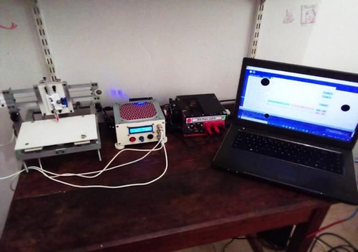
International Research Journal of Engineering and Technology (IRJET)                                  e-ISSN: 2395-0056
        Volume: 08 Issue: 06 | June 2021               www.irjet.net                                          p-ISSN: 2395-0072

considered the best approach to manufacture parts                     plasma cutting machines, 5-axis machines, 3-D printers,
throughout the 19th century, several challenges remained;             pick and place machines, etc. [1].
which include the production of tapes being expensive,
tapes being fragile, and difficult to pair. Nowadays, digital         This paper focuses on CNC plotter machines. Plotter
processing technology is used instead. This type of                   machines are the type of CNC machines that are commonly
technology uses computers to store, generate and stream               known to produce vector graphic sketches on paper using
the machine control instructions onto CNC machines. The               a pen, but in some applications, they are used as cutting
CNC technology uses Geometric Code (G-Code) and                       machines, replacing a pen with a cutting knife i.e. in vinyl
Miscellaneous Code (M-code) as their programming                      and lather cutting process[9]. This type of plotters, which
language instead of punched cards. [5]. Figure 2 shows an             possess the cutting capabilities are called cutting plotters,
example of a CNC milling machine, reading instructions                while those used to produce sketches are called pen
from a G-Code file to reproduce a custom design on a piece            plotters [9]. The plotter machines were commonly used
of aluminum.                                                          before the advent of laser printer machines around the
                                                                      1980s, and they were a perfect alternative over
                                                                      conventional printers since they relatively produced line
                                                                      sketches much faster and at a much higher accuracy [9].
                                                                      Even though the birth of laser printers eliminated most of
                                                                      the roles commonly performed by plotters, they are still
                                                                      useful in many manufacturing industries [9].

                                                                      The rest of this paper is organized as follows. Section 2
                                                                      outlines some literature on CNC technology basics. Section
    Figure 2: G-Codes and M-codes from a computer used as             3 gives a detailed account of the design and
              instructions to a milling machine [6]                   implementation of the mini CNC machine prototype. In
Before the invention of NC technology, machine tools were             section 4 the image vector and different shapes produced
manually controlled by the machinists, as a result, the               by the plotter will be observed and compared with their
industrial and commercial manufacturing processes were                respective input templates. Section 5 concludes this paper
often slow and inefficient, and of low quality due to the             by outlining some major findings drawn from this work as
fallibility nature of humans [1]. The advent of CNC                   well as the remarks on future developments.
machines was the state of the art in production industries.
                                                                      2. CNC TECHNOLOGY BACKGROUND
It brought about improved production accuracy, and
efficiency, simplicity, flexibility, reduced costs [1]. It also       While the CNC machines use graphical codes (G-Codes)
led to high-quality products, reduced production time,                and miscellaneous codes (M-Codes) as their programming
reduced chances of product damages, etc. These were all               language, the first step in CNC machining is to create a
achieved from the fact that CNC machines used computers,              custom 2D or 3D vector design using the CAD software
and their operation was automatic i.e. CNC machines                   installed in a computer. The finished CAD design is then
required minimal assistance from humans.                              saved in the file format that corresponds to CNC
                                                                      machining, which is predominantly Exchange of Product
CNC machines were normally known to be industrial
                                                                      Data Files (STEP files) and Initial Graphics Exchange
machines because they were very expensive [7]. However,
                                                                      Specifications Files (IGES files). The concept of file formats
nowadays this technology is becoming increasingly more
                                                                      has become handier in the competitive and ever-changing
popular and is extending to small-scale manufacturing
                                                                      software space, in the parts manufacturing process, to
processes in some developed countries. CNC machines
                                                                      enable sharing of CAD information between programs
currently take different forms and sizes and are sold at
                                                                      without the use of any tedious conversion processes.
relatively affordable costs in some countries. This makes it
possible for some individuals to own CNC machines i.e. the            CAD software is a platform used to create 2-3D vector
DIY CNC’ers are currently able to manufacture the CNC                 blueprint designs within a computer [1]. A CAD design file
machines for their personal use [8]. The most common                  is then passed through another important manufacturing
CNC machine types are CNC plotters, CNC laser cutting                 software called Computer-Aided Manufacturing (CAM),
machines, CNC lathe machines, CNC milling machines, CNC               which is responsible for generating highly optimized tool
                                                                      paths to be followed by the CNC machine [2]. The CAM

© 2021, IRJET        |     Impact Factor value: 7.529             |    ISO 9001:2008 Certified Journal            |   Page 1488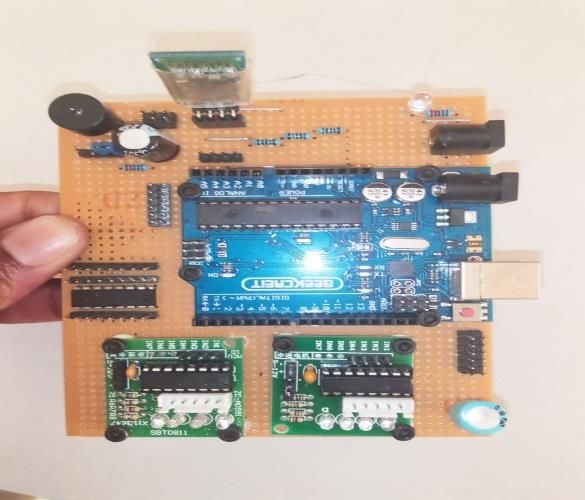
International Research Journal of Engineering and Technology (IRJET)                              e-ISSN: 2395-0056
        Volume: 08 Issue: 06 | June 2021            www.irjet.net                                         p-ISSN: 2395-0072

software outputs a G-Code file, which is a language of CNC
machines. The CAM and CAD software can be used
independently, but a CAM program usually exists as an
add-on to CAD software [10]. Some examples of CAD
software are FreeCAD, TinkerCAD, Sketchup, and Blender,
while those of CAM software are CAMWorks, NX CAM,
MasterCAM, Fusion 360, and Solidworks CAM [10].                   Figure 4: Manufacturing information flow from CAD to CNC
                                                                                             [13]
IGES and STEP file formats are the popular file formats
created from CAD programs to facilitate sharing of CAD            2.1 Software Subsystem
designs to work across various design systems [11]. The
IGES file format was created by the U.S. Government               The CNC program file contains the instructions which
around the 1970s with a realization that more money and           control the motion and state of the system [16]. Since the
time are being wasted in the process of converting shared         program is normally in the higher-level languages i.e. G-
data files across various software systems [11]. The use of       Code, there has to be a mechanism inside the system to
IGES file format made it through to 2D and 3D CAD file            translate/decode the instructions from the higher
sharing across major CAD software systems, and thus               language into the language that can be understood by the
became a standard across various fields such as aerospace,        machine, and usually, this mechanism is implemented
military, etc. At around the 1980s, the STEP file format          inside the system’s controller. The controller’s program
came into being [11]. This format came along with some            interpreter will receive the instructions set from the CNC
improvements upon IGES and became widely accessible               program file in the form of a text and will process and
around the 90s. The STEP format is continually gaining            convert the textual instructions into electrical pulse
popularity with continuous improvements in its                    signals which are in the form of 0’s and 1’s whereby 0
functionalities across an increasingly growing number of          represents the absence of a signal while 1 represents the
CAD systems [12]. Figure 3 shows the workflow of                  presence of the electrical signal. The electrical signals are
CAD/CAM for subtractive (Mill, Lathe, etc.) and additive          later converted into either mechanical motion or
(3D printer) CNC machining.                                       mechanical state control instructions.

                                                                  The motion along x, y, and z dimensions are normally
                                                                  described as shapes in the graphic vector space using the
                                                                  Cartesian plane, but when dealing with computer graphics,
                                                                  the approach of normal Cartesian plane description fails.
                                                                  The solution to this failure requires a transformation
                                                                  algorithm from the graphic vector space to the raster
                                                                  space, and the process is called Rasterization [17]. Figure
                                                                  727 below depicts an example of the rasterization of a
         Figure 3: The workflow of CAD/CAM [10]                   straight line graphic vector into a computer graphic
                                                                  format.
Figure 3 shows the workflow of the CAD/CAM process in
CNC machining. The first step, shows the creation of a 2D
or 3D model of a part, using CAD software, such as
SolidWorks, Autodesk, etc. The CAD file design is then
saved as an IGES, STEP, or Native CAD File in the case of a
2D model, and saved as an STL file for 3D models. An STL
(stereolithography) file format is a standard for 3D
systems. These CAD files are then transferred to CAM
software and converted to G-code, which will later be used
by CNC machines to manufacture parts. The information               Figure 72: Rasterization of a straight line graphic vector
flow chart shown in Error! Reference source not                                               [17].
found.4 depicts clearly, the compositions of each file in
                                                                  In Figure 727 a black straight line is shown; which is
the manufacturing CAD/CAM workflow.
                                                                  normally represented by a line equation (1). The

© 2021, IRJET       |    Impact Factor value: 7.529           |    ISO 9001:2008 Certified Journal            |   Page 1489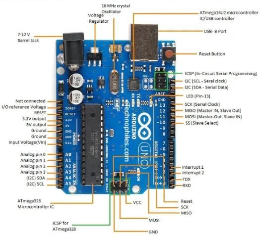
International Research Journal of Engineering and Technology (IRJET)                              e-ISSN: 2395-0056
        Volume: 08 Issue: 06 | June 2021            www.irjet.net                                         p-ISSN: 2395-0072

corresponding representation of the line in the Raster
plane is shown using the grey boxes in the grid, and it is
conspicuous how complex, simple vector graphic shapes,
could be represented in this space.

                        ( )                             (1)

Interpolation algorithms (linear [18] or circular [19]) are
typically used to estimate the intermediate (and
fractional) pixel positions over which the line (or curve)
crosses.                                                                           Figure 83: A stepper motor

2.1 Mechanical Subsystem                                          2.1.2 Servo Motor
                                                                  A servo motor is an electromechanical system that
The concept of CNC machining is mainly to automate the            converts electrical signals into mechanical motion. This
conventional manual toolsets such as hand-saw, drilling           type of motor is normally used in precision control
machine, and grinding machine. This automatic feature is          applications such as CNC machines, military robots with
achieved by using the motors to drive the CNC tool i.e.,          bomb detection, and other applications of position control.
spindle along the paths declared in the CNC program. In           Even though servo motors and stepper motors are both
the CNC machining process, precision is of higher priority,       meant for position precision control applications, the two
thus the motors to be used to establish these motion sets         are quite different, and in some cases, one motor type is
have to be very special motors, whose rotary motions can          preferred over the other. The stepper motors are
precisely be controlled. The commonly used motor types            commonly preferred in open looped control applications
in CNC machines are stepper motors and servo motors.              whereas servo motors are normally used in closed-loop
                                                                  control applications because of their unique positioning
2.1.1 Stepper motor                                               feedback mechanism.
A stepper motor is an electromechanical device that is
sometimes referred to as a special DC brushless                   Servo motors exist in various sizes and forms, which can
synchronous motor, whose rotation is of discretized equal         be operated either by AC or DC. The AC servo motors are
steps as opposed to normal brush DC motors, with                  normally used in heavy-duty machines, due to their
continuous rotation[20]. It functions by converting the           capability to handle heavy currents, while the DC servo
pulses of electrical signals into mechanical rotary               motors are used in smaller applications that involve
motion[20]. A type of motion used by stepper motors,              precision control. The frequency of the input voltage signal
where a full rotation is divided into an equal expansive          and the number of magnetic poles are the key features
number of steps makes it easier to control. The position of       that determine the speed of the motor. There are three
the motor can precisely be controlled by the pulse signals        basic types of servo motors which include positional
which are made to generate unit step of a specific size,          rotation, linear, and continuous rotation.
thus stepper motors can be successfully employed in open
looped precision control systems, operating without any           2.1.3 Motor Driver
feedback mechanism or position sensor in as long as the           In CNC machining, the motion of the precision motors (i.e.,
motor sizing in respect to torque and speed are adequately        stepper and servo motors) is controlled via the CNC
selected for an application. In the situation whereby the         controller, which generates the PWM control signal
motor is not properly sized for an application, the stepper       patterns to rotate the motor back and forth in discrete
motor is likely to miss some step without any                     steps [21]. However, the motors are usually not connected
compensation mechanism and would result in errors in              directly to the controller pins due to their high current
the construction of the programmed paths. Error!                  requirements, and a dedicated precision motor driver
Reference source not found.8 shows an example of a                board is always used [21]. The motor drivers are the
real-life stepper motor.                                          interfacing circuit boards between the CNC controller and
                                                                  precision motors. They are used to translate low currents
                                                                  from the controller board into high currents required by
                                                                  the motors [22]. Figure 949 shows an example of the most
                                                                  common unipolar stepper motor (28BYJ-48), and its

© 2021, IRJET       |     Impact Factor value: 7.529          |    ISO 9001:2008 Certified Journal              |   Page 1490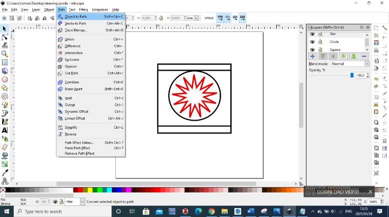
International Research Journal of Engineering and Technology (IRJET) e-ISSN: 2395-0056
Volume: 08 Issue: 06 | June 2021 www.irjet.net p-ISSN: 2395-0072
circuit connection to the controller together with their The use of Microcontroller Based CNC controllers is
corresponding table of the motor control signal patterns. gaining popularity, and this is due to the accessibility and
low prices of microcontroller boards [25]. One example of
the microcontroller board is shown in Figure 11611 and is
called the Arduino Uno microcontroller board.
Figure 94: The ULN2003a stepper motor controller circuit
with the control signal patterns table [22].
The UNL2003a stepper drivers are dedicated to the 28BYJ-
stepper motors, and an example of their kit is shown in
Figure 10510.
Figure 116: Arduino Uno Microcontroller board [25].
3. DESIGN AND IMPLEMENTATION
In this section, the focus is on the design and
implementation of the NC plotter, which would be
subdivided into three major compartments; being NC
frame design and implementation, NC circuit design, and
NC software.
Figure 105: ULN2003 Driver Board and 5 wire 5v 4 phase 3.1 Frame Design and Implementation
28BYJ-48 unipolar stepper motor [23].
3.1.1 Hardware requirements:
2.1.4 CNC Controller
The CNC controller is a digital circuit that acts as the brain Aluminium angle iron 1.5 x 19 mm & 1.5 x 25 mm
of the CNC machine [24]. It is the source of all the RM3ZZ 12mm V-Groove Guide Bearing Shielded
(x8)
intelligence of the CNC machines and in control of the
Eccentric Nut Spacers (x12)
operation of CNC machining processes. The CNC machine Socket Screws and Washer kit
controllers are programmed to decode the g-code M6 75 mm hex (nuts and bolts) (x4)
instructions from the computer and translate them into M5 30 mm Machine screws (bolts & nuts) (x10)
precise motor rotary steps, which are then sent to the GT2 pulley head
stepper motor drivers to obtain the mechanical 25 mm Nylon Bearing Pulley idler
movements [24]. There are various types of CNC Clear Plastic Sheet (e.g., Drawing board) 3mm
CD/DVD Drives Rail System
controllers, and these include [24]:
28byj-48 Stepper Motors (x2)
Plastic furniture corner bracket 27.5 x 26.5 mm
Industrial OEM CNC Controller
(LxW) Mounting Hole:M3 (x2)
CNC Retrofit Controller
Arduino Positional servo motor (x1)
PCB Based CNC Controller
Ball-bearing 16 mm out diameter & 2 mm in
Microcontroller Based CNC Controller
diameter (x1)
Breakout Board CNC Controller
Ballpoint Pen Spring
etc.
© 2021, IRJET | Impact Factor value: 7.529 | ISO 9001:2008 Certified Journal | Page 1491
International Research Journal of Engineering and Technology (IRJET) e-ISSN: 2395-0056
Volume: 08 Issue: 06 | June 2021 www.irjet.net p-ISSN: 2395-0072
3.1.2 Tools: Arduino Positional servo US$ 5.73 M 80.00
motor
Hand Saw
Drilling machine and drill bit set
Ball bearing 16 mm out M 1.40 M 1.40
Wood-working file (i.e., flat and or triangular file)
diameter & 2 mm in
Allen key Set
diameter
Ballpoint Pen Spring M 4.99 M 4.99
3.1.3 Estimated Cost:
Table 1: Table of NC frame quotation prices.
Contact Glue M 20.00 M 20.00
Material Unit Cost Total Cost
Aluminium angle iron 1.5 x M 96.00 M 96.00
19 mm M 1, 465.44
Aluminium angle iron 1.5 x M 109.99 M 109.99
25 mm
RM3ZZ 12mm V-Groove US$ 9.65 M 134.71 Most of the materials found on the table can be salvaged
Guide Bearing Shielded (12 from old equipment at home for someone interested in
pcs) implementing a similar plotter design at home to reduce
Eccentric Nut Spacer (10 US$ 7.84 M 210.88 the manufacturing costs e.g., an old engineering drawing
pcs) board was used instead of buying M 331.12 PVC sheets,
M2CH2 M2 Carbon Steel US$ 7.99 M 111.54 CD/DVD Drives Rail System salvaged from old CD/DVD
Allen Bolt 4-16 mm Hex player, etc. Delivery and transport costs have not been
Socket Cap Screw Metric
included in Table 1.
Assortment Kit (180 pcs)
Metric Flat Washers (180 US$ 8.39 M 117.12
pcs) 1.1.1 Frame Design:
The NC frame is designed using the 3D CAD software
M6 75 mm hex (nuts and M 21.50 M 21.50 called Sketchup. This software is preferred because it is
bolts) (4 pcs) very user-friendly and open source. The sketch design in
this paper is mainly used to visualize the plotter frame in
3D to access the feasibility of the design before the actual
M5 30 mm Machine screws M0.5 M 5.00 implementation. The advantages of the sketching process
(bolts & nuts)
are that it facilitates the reasonable choice of the type of
GT2 Pulley Head US$3.23 M 90.18 materials to be used, easy dimensioning of a product, easy
costs estimation process and to easily access whether the
design is practical. Error! Reference source not found.
Nylon Bearing Pulley idler US$1.18 M 32.94 show the design process of the NC frame.
25 mm
Clear Plastic Sheet (e.g., US$ 23.72 M 331.12
Drawing board) 4ft x 8ft x
3mm
CD/DVD Drives Rail System
28byj-48 Stepper Motors (2 US$ 5.77 M 80.55
pcs)
Plastic furniture corner M 18.40 M 18.40
bracket 27.5 x 26.5 mm Figure 12: Isometric view of an NC frame Design
(LxW) Mounting Hole:M3 (2
pcs)
1.1.2 Implementation
Error! Reference source not found.shows the frame
design made from aluminum angle profiles and plastic
© 2021, IRJET | Impact Factor value: 7.529 | ISO 9001:2008 Certified Journal | Page 1492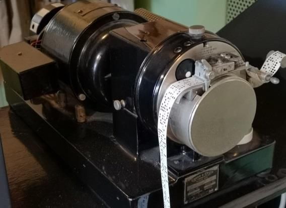
International Research Journal of Engineering and Technology (IRJET) e-ISSN: 2395-0056
Volume: 08 Issue: 06 | June 2021 www.irjet.net p-ISSN: 2395-0072
plain sheets. The aluminum and plastic were preferred in The pen holder mechanism was made from plastic pair of
this paper because of their lighter weight which would campus and was glued onto the plastic sheet using contact
result in a portable and lightweight frame structure. Apart glue. The rail system is made from the CD/DVD drive
from that, the aluminum materials are easy to process and system shafts using the ballpoint pen spring to always
do not require expensive and complicated tools to process push the pen holder mechanism downward. The reason
i.e., a metal cutting hand saw can still be used effectively to why the spring was used was to facilitate a smoother pen
nicely cut aluminum angles instead of a cutting grinder movement. The spring would absorb any machine
machine, a manual hand drilling machine instead of an paper_base surface imbalances and roughness by allowing
electric hand drilling machine to make holes and again the the pen holder to stretch with the surface geometry and
high-quality drill bits are not necessary to effectively get roughness. The eccentric nut spacers between the wheel
the best results. All the qualities just mentioned about the gentry plate and the rail plate offer an allowance for the
aluminum and plastic materials ultimately address the servo motor to slide into the Z-Axis system. The ball
issue of production cost and portability of the NC machine. bearing on the pen holder plate also facilitates the
smoother jerking of the pen holder plate, by the servo arm
The design structure mainly uses bolts and nuts to fasten by simply sliding on the arm without gripping.
the angle irons together. This facilitates simpler and
flexible product which can easily be assembled and 1.2 NC Circuit Design
disassembled to make the system mobile and easy to
maintain. The type of screws used was also carefully 1.2.1 Hardware requirements:
selected. The socket screws were found to be the perfect ULN2003A stepper drivers (x2)
selection for this application since they offer more HC-06 Bluetooth module
clamping force than other standard screws such as 10k potentiometer
machine screws and other formats of small fasteners. The LED Screen (2x16)
frame legs are also made from 6 x 75 mm hex screws to ON/OFF LED
enable the structure legs to be fastened to eliminate any 220k, 1k, 2k resistors
Power Jack
mechanical vibrations that may affect the accuracy of the
Buttons (x2)
system.
Arduino Uno
Buzzer
The type of stepper motors used in the design is 28byj-48
470uF capacitor
stepper motors. These motors provide high torque at
Male and female PCB connector strips
reasonable speeds (around 500rpm), and this calls for PCB Jumper wires
more accuracy of the plotter machine. The plotter rail Heat shrink 3mm
system is made from v-slot wheels which were made
specifically for precision machine rail systems. The wheels 1.2.2 Tools:
go hand-in-hand with the adjustable spacers, to control Soldering iron & wire
the creep on the metal rails. Wood-working flat file
Drilling machine & drill bit set
Allen key Set
Copy saw
Lighter
1.2.3 Estimated Cost:
Table 2: The estimated cost of all the electronics required.
Material Unit Cost Total Cost
ULN2003a Stepper Motor
US$ 2.15 M 60.03
Driver
HC-06 Bluetooth
US$ 4.31 M 60.17
Figure 7: Design Implementation of the NC Plotter Machine module
© 2021, IRJET | Impact Factor value: 7.529 | ISO 9001:2008 Certified Journal | Page 1493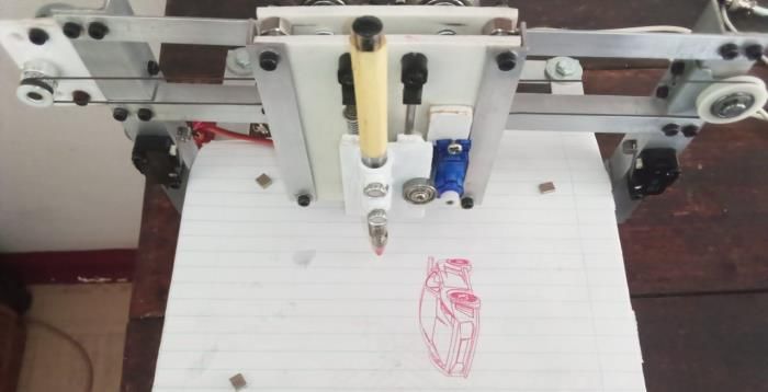
International Research Journal of Engineering and Technology (IRJET)                                 e-ISSN: 2395-0056
         Volume: 08 Issue: 06 | June 2021                 www.irjet.net                                       p-ISSN: 2395-0072

         10k potentiometer          US$ 2.88         M 40.20          The type of microcontroller used for this design paper is
                                                                      Arduino Uno. The board was preferred over many others
         LED Screen (2x16)          US$ 3.69         M 51.51          due to its moderately lower costs and the number of pins
                                                                      it offers i.e., the paper required about 14 input-output pins
           ON/OFF LED                M 1.00           M 1.00
                                                                      which the exact number of pins in Arduino Uno.
                                                                      Otherwise, any other microcontroller with an adequate
            220k, 1k, 2k
                                     M 1.50           M 4.50          number of pins (e.g. Arduino Mega) would still be ok, even
             resistors
                                                                      though they are a bit costlier than Arduino Uno.
          Power Jack (50
                                    US$ 4.31         M 60.17          The type of stepper motors and stepper drivers used in
              pcs)
                                                                      the design are 28BYJ-48 stepper motors and ULN2003a
         Buttons (10 pcs)           US$ 3.73         M 52.07          stepper drivers respectively. Usually, the selection of
                                                                      motors and driver to be used in the design of the CNC
       Arduino Uno                  US$ 5.29         M 73.84          machine is a very critical and long process and helps
                                                                      optimize the performance of the machine in terms of
          Buzzer (5 pcs)            US$ 1.59         M 22.20          torque, and maximum speed to improve the production
                                                                      process quality. However, in this proposed design, not
          470uF capacitor            M 1.20           M 1.20
                                                                      special attention was given to the process of stepper and
         Male Female PCB                                              driver selection because the gentry systems of the
                                    US$ 2.26         M 31.55          machine were made to be very light (used aluminum and
         connector Strip
                                                                      plastic) apart from the fact that the machine is also very
         PCB Jumper wires           US$ 1.23         M 17.17          small. The 28BYJ-48 stepper motors are geared to have
                                                                      very high torque and reasonable speed, so it was very
    Heat shrink 3mm                 US$ 2.12         M 29.59          obvious that they should be adequate for this application.
                                                                      The drivers and motors are usually sold as a kit, and a
                                                                      cheaper one for that matter, hence why they were both
                                                                      selected for this application.
  M
505.20                                                                The servo motor type that was selected for this application
                                                                      was the 1800 positional servo motors. This type of motor
It is also important to note that it is usually wise to have 2-
                                                                      was also preferred simply because it is cheaper and easily
3 extra components as the backup to the components that
                                                                      accessible i.e., they are usually present in the starter
may accidentally get damaged in the manufacturing
                                                                      Arduino kits. Another important reason, for the selection
process.
                                                                      of this motor, is that they have a relatively very high
1.2.4 Circuit Design:                                                 torque which would be more than enough for this
                                                                      application, not leaving behind the fact that they were
                                                                      could easily be integrated with the proposed z-axis design.

                                                                      There is nothing special for the selection of the HC-06
                                                                      Bluetooth module type used in the design. Any other
                                                                      Bluetooth module (e.g. HC-05) would still be fine, and the
                                                                      HC-06 just happened to be the one accessible. The LCD
                                                                      screen is used to display the g-code, and other important
                                                                      technical messages such as errors and the potentiometer
                                                                      are used to adjust the brightness of the screen. The buzzer
                                                                      is used to indicate the booting process of the machine, and
                                                                      the two buttons are the emergency stop and tool change
                                                                      buttons. The capacitor connected to the servo motor is
                                                                      used to improve the servo motor’s operation, to ensure
       Figure 18: The circuit design of the NC plotter.               stable motion.

© 2021, IRJET        |     Impact Factor value: 7.529             |    ISO 9001:2008 Certified Journal            |   Page 1494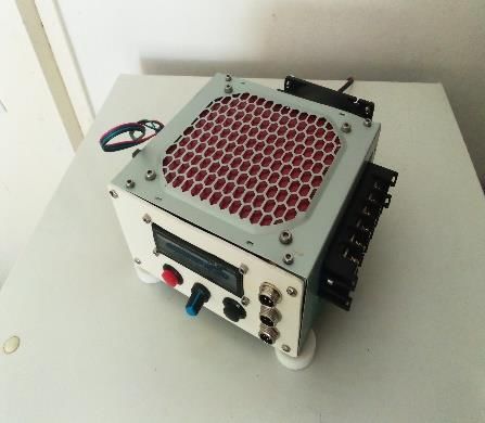
International Research Journal of Engineering and Technology (IRJET) e-ISSN: 2395-0056
Volume: 08 Issue: 06 | June 2021 www.irjet.net p-ISSN: 2395-0072
1.2.5 Implementation: Wood-working file
Drilling machine & Drill bits Set
Flat type Screw Drivers Set
Error! Reference source not found.17 shows the
implemented design of an electronics enclosure for the NC
machine.
1.3.3 Estimated Cost:
Table 3: Estimated cost of an electronics enclosure
Material Unit Cost Total Cost
Machine screws
Figure 15: The NC plotter PCD. (bolts & nuts) M 15.00 M 15.00
3.5mm (50 pcs)
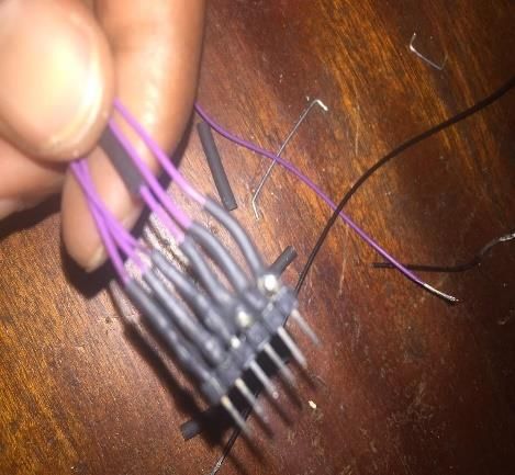
The electronic components and modules were bought
together on a single solder type PCB, and the connections GX 5-way
US$ 5.99 M 250.86
were made using the PCB male and female connector connectors
strips.
Heat shrink
1.2.6 LCD Screen Connection PCB: 3mm (length US$ 2.51 M 35.04
To ensure clean packaging, the LCD screen, due to its 2.5 m)
numerous pins had also called for the screen connection
Insulation tape M 34.50 M 34.50
PCB, which is shown in Figure 169.
Potentiometer
Knob cap (10 US$ 4.31 M 60.17
pcs)
M 395.57
1.3.4 Implementation:
Figure 169: The NC plotter LCD screen connection PCB.
1.3 Electronics Enclosure
1.3.1 Hardware requirements:
ATX desktop power supply case
Clear Plastic sheet (e.g., drawing board) 3mm
2mm metal sheet
Machine screws (bolts & nuts) 3.5mm (x4)
Socket screws and washers Figure 1710: A complete electronics enclosure.
GX 5-way connectors
Heat shrink 3mm 1.4 NC Power Supply
Insulation tape
There are various options for powering the plotter
Potentiometer Knob cap
machine in this paper since most of the electronics used
1.3.2 Tools: require a 5v supply. To cater for the coolant fan powering,
an extra 12v voltage was required and the closest option
Copy saw
was to reuse a PC power supply.
© 2021, IRJET | Impact Factor value: 7.529 | ISO 9001:2008 Certified Journal | Page 1495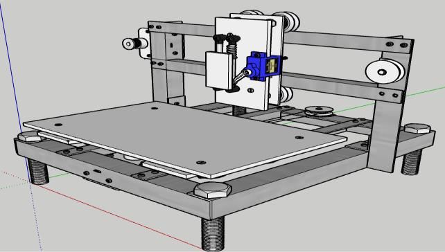
International Research Journal of Engineering and Technology (IRJET) e-ISSN: 2395-0056
Volume: 08 Issue: 06 | June 2021 www.irjet.net p-ISSN: 2395-0072
1.4.2 Hardware requirements: 1.4.5 Implementation:
Banana plugs (x6) (3 black, 3 red)
Switch
LEDs (x2)
330ohm resistors
10-ohm 10w Power resistor
1-Amp fuse
Laminated front panel design
Zero PCB
ATX PC Power Supply Case
1.4.3 Tools: Figure 1811: NC bench power supply from the PC power
Drilling Machine & Drill bits Set supply.
Hear shrink & Lighter
Soldering iron The power supply enclosure front panel was designed
Wood-working file using Inkscape CAD software colored-printed and
Screw Drivers Set laminated to protect the printed paper. It was then glued
at the front side of the case as shown in Figure 181118.
1.4.4 Cost Estimate:
Table 4: Estimated cost of building a power supply. 1.5 NC Software
Material Unit Cost Total Cost 1.5.2 Interpreter
The function of an interpreter in CNC programming still
Banana plug (2xBlack & retains its meaning as in any other programming language.
M 3.50 M 21.00
2xRed) The NC interpreter converts the G-code instructions text
into machine language instructions to control the NC
Switch M 17.99 M 17.99
motions and other miscellaneous features.
LED (Redx1, Green x1, Table 5: g-code commands for the CNC plotter design.
M 1.00 M 2.00
Blue x1)
COMMAND MEANING
330ohm resistors M 0.50 M 1.00
G00 & G01
Move to position XY at the
10-ohm 10w
M 15.00 M 15.00 G01 [X(n1)] [Y(n2)] [F(n3)]
federate F
Power resistor
Laminated front G04
Wait/Pause for n
panel design G04 P(n)
milliseconds
M 12.00 M 12.00
(printing +
laminating) Metric Scale selection
G21
command
Zero PCB (3 cm x
M 7.50 M 7.50 G90 Absolute mode
3 cm)
M G92
Relative mode
76.49
G92[X(n1)] [Y(n2)] [Z(n3)]
M01 Pen change command
M114 Position reporting command
M300 M300 S50.00: Pen up
M300 S50.00 M300 S30.00: Pen down
© 2021, IRJET | Impact Factor value: 7.529 | ISO 9001:2008 Certified Journal | Page 1496International Research Journal of Engineering and Technology (IRJET) e-ISSN: 2395-0056
Volume: 08 Issue: 06 | June 2021 www.irjet.net p-ISSN: 2395-0072
M300 S30.00 Figure 211321 shows a portion of the generated g-code
file opened in a notepad text editor.
M18 Drivers Off
1.5.3 Generating the G-Code
The custom design was generated using Inkscape
software, and the G-code Unicorn Master Inkscape
extension was used to generate the corresponding g-code
for the custom design. The default units used in the
document were in millimeters, and the document size was
set to 100 x 100 mm which is a perfect fit in the machine
plotting range of 250 x 250 mm. The graphic object was
designed in 3-layers named (star, circle, and square)
shown at the right-side panel of the document to enable a
Figure 2113: A portion of a generated g-code file.
pen change functionality at every layer change. A
successful design of the graphic object was then followed The g-code file was then sent to the CNC plotter machine,
by the conversion of the object design into design line line by line, to reproduce a custom design encoded in g-
paths as shown in Figure 1912. code data in Figure 211321.
1.5.4 G-code Streaming:
The generated g-code would ultimately be sent line by line
to the NC plotter machine via the USB or Bluetooth serial
port, and this called for the development of a very simple
g-code sender software called Moeti CNC Machines G-Code
Sender. This software offers a very straightforward GUI
with limited functionalities since it was mainly dedicated
to sending the g-code instructions from the file in the PC to
the NC machine. This G-Code sender was implemented
using java programming language confined in processing
sketchbook. The interface for the g-code streamer was
Figure 1912: Converting a graphic object into line paths. developed using the controlP5 and G4P GUI processing
libraries.
The conversion of an object into line paths format is
followed by saving a design with a .gcode file extension The streaming process will continue with the previously
made possible by the MakerBot Unicorn Gcode Inkscape generated g-code file, and show in steps how to stream the
extension. g-code file to the NC machine using Moeti CNC Machines
software. The first step is to connect the software to the
correct com port depending on the means of
communication used i.e., the com port used in USB Serial
communication would differ from the one used in
Bluetooth Serial Communication. The com ports can be
validated in the PC device manager. Figure 221422 shows
the process of selecting the com port in Moeti CNC
Machines software.
Figure 20: Saving a design in a .gcode file extension.
© 2021, IRJET | Impact Factor value: 7.529 | ISO 9001:2008 Certified Journal | Page 1497International Research Journal of Engineering and Technology (IRJET) e-ISSN: 2395-0056
Volume: 08 Issue: 06 | June 2021 www.irjet.net p-ISSN: 2395-0072
Figure 2517: Manual control context menu showing the
Figure 2214: Selecting the Com Port in Moeti CNC Machines motion buttons and the keyboard hotkeys.
software.
The g-code sender in Figure 241624 displays some g-code
When the software is successfully connected to an
commands received from the file on the PC from a
appropriate com port, the g-code file can then be browsed
directory shown below the file button on the left side of
from the PC in an appropriate directory by clicking on the
the interface. It also shows the progress bar which
file button on the left side of the GUI. The g-code file is
displays the plotting progress as a percentage determined
selected and opened, and to stream the file, the send
by (current line number/total number of lines in the file) x
button is clicked. This process is demonstrated in Figure
100%. The keyboard keys are also supported to manually
2315, and Figure 2416 shows the streaming process of the
move the machine axis, and the hotkeys are the navigation
g-code file.
keys, page up and page down, etc. By pressing the manual
button, the manual control context menu is displayed as
shown in Figure 251725.
4. TEST RESULTS & DISCUSSION
This section is designed to determine whether the
machine works and adheres to the following objectives,
Mass Production Capability
Portability (i.e., lighter structure)
Cost-Effectiveness
Ability to write text
Draw any form of shape (Regular and Irregular)
Figure 2315: Importing the g-code file into Moeti CNC 4.1 Complete Product
Machines software.
When the product is complete, it would be composed of
the NC plotter machine structure, electronics box, power
supply, and Moeti CNC Machines software installed on the
PC. Figure 261826 shows an overview of the complete NC
plotter machine.
Figure 2416: The generated g-code streaming process to the
NC plotter using Moeti CNC Machine g-code sender.
© 2021, IRJET | Impact Factor value: 7.529 | ISO 9001:2008 Certified Journal | Page 1498International Research Journal of Engineering and Technology (IRJET) e-ISSN: 2395-0056
Volume: 08 Issue: 06 | June 2021 www.irjet.net p-ISSN: 2395-0072
of the angle profile per unit NC Plotter to about
M109.99/3 = M36.66. The costs of the NC machines found
in AliExpress range between US$ 120.00 – US$ 700.00
with an exception to delivery costs, thus the mass
production of the custom design introduced in this paper
could relatively be cheaper than importing the depicted
NC machines in Lesotho.
4.3 Product Testing
This section deals with the testing of the NC plotter
capabilities, to observe whether the final product gives the
results which were expected as per the goals and
objectives of the paper. Figure 271927 shows the plotter
Figure 2618: Complete NC plotter overview. output of the g-code generated in the previous sections.
The NC frame of the complete CNC plotter was found to be
very firm, light, and stable. In design, it was mostly made
from nuts and bolds and this had made the end product to
be very flexible, repeatable, and mobile, thus the structure
could easily be maintained through a quick disassembling
process. With the quality for repeatability in the building
of the CNC plotter, it would imply the potential of the
machines to be mass-produced.
Figure 2719: The CNC plotter machine results from the
4.2 Estimated Porduction Cost generated g-code.
Table 6: NC Plotter Manufacturing Total Estimated Cost The NC machine plotter output result shown in Figure
271927 seems to match with the custom CAD design
Type Cost object in Figure 191219.
Hardware Design M 1, 465.44
Electronics M 505.20
Power Supply M 76.49
Enclosure M 395.57
Total Cost M 2, 442.70 Figure 2820: CAD Design of the Bluetooth icon.
The total estimated cost of building the NC plotter for
commercial and mass production purposes was found to
be around M 2, 442.77. Although the estimated cost looked
a little high, intuitively, it was still reasonable. Looking
closely at Table 6, most of the bought components were
bought in bulk, which means that similar expenses would
be exclusive in the preceding building of several NC
machines. With this thought, the cost price for the unit NC Figure 2921: The Plotter results of the Bluetooth icon.
plotter machine production would immensely be reduced
The NC Plotter machine was also expected to be able to
i.e, a single 6m 25mm M109.99 angle iron can produce
reproduce any given text, and plotter results are shown in
about 3 NC plotter machines, which renders the total cost
Figure 302230.
© 2021, IRJET | Impact Factor value: 7.529 | ISO 9001:2008 Certified Journal | Page 1499International Research Journal of Engineering and Technology (IRJET) e-ISSN: 2395-0056
Volume: 08 Issue: 06 | June 2021 www.irjet.net p-ISSN: 2395-0072
Figure 3022: Inkscape text design.
Figure 33: The Lamborghini NC plotter results.
The design and implementation of the mini CNC plotter
were a success, and the results obtained were quite
impressive. However, the major challenge encountered in
the implementation of the machine was that most
materials used in the paper were ordered from outside the
country. That ultimately increased the manufacturing
costs for this particular startup machine because most of
Figure 3123: The plotter text results the materials were bought in bulk as a backup for anything
that might go wrong in the middle of the manufacturing
Figure 302231 shows the success of the plotter to process.
reconstruct the Inkscape text ‘hello’ onto the piece of
paper. The reproduced is double lines, but this property The machines to be designed in the future would be made
can be changed from the design by editing the line paths in such a way to minimize the number of imported
from double to single line path, otherwise the results materials i.e., the linear guide v-wheels will be substituted
satisfactory with the normal ball bearings, and the driver boards be
redesigned to make use of the electronic components
The NC plotter was also tested on very complicated already found in the country. Another challenge was to
designs to observe its performance, and most of the find a regulated power supply with adequate power to
results obtained were satisfactory. One instance of the offering both the 5v and 12v for the electronics coolant,
tested designs is shown in Figure 2432, and the NC plotter and the power supply design used in this paper made the
results are shown in Figure33. overall paper to be a little bulky, and in the future, a
smaller power supply, which would fit inside the
electronics box will be redesigned.
5. CONCLUSIONS
The motive behind these papers came from an observation
that not many people acknowledge and take advantage of
the CNC technology in Lesotho. The success of this paper
could work as a wake-up call and an introduction to CNC
Figure 242: The Lamborghini Inkscape graphic vector machine manufacturing companies in Lesotho for quality
design. productions. It was found in the results of this paper, that
it could be quite expensive to import CNC machines from
other countries as compared to when produced in
Lesotho. Another advantage of developing these machines
in Lesotho is that it would be easier to maintain them, and
can be easily accessible to anyone in the country hence
improve their livelihood.
© 2021, IRJET | Impact Factor value: 7.529 | ISO 9001:2008 Certified Journal | Page 1500International Research Journal of Engineering and Technology (IRJET) e-ISSN: 2395-0056
Volume: 08 Issue: 06 | June 2021 www.irjet.net p-ISSN: 2395-0072
In this paper, the mini CNC plotter (250 mm x 250 mm) [7] “CNC Machining Definition, Processes, Components,
was designed and implemented. The structural design was & Equipment.”
developed using a free and open-source 3D vector design https://www.thomasnet.com/articles/custom-
manufacturing-fabricating/understanding-cnc-
software called SketchUp, and the frame was designed to
machining (accessed Oct. 22, 2020).
be rigid, light, and stable to facilitate mobility, and
improved the operation process. The machine was mostly [8] B. Warfield, “What is CNC Machining and CNC
implemented using fasteners for easy maintenance and Machines? [2020 Easy Guide],” CNCCookbook: Be A
Better CNC’er, Jul. 21, 2019.
repeatability and made gave a design a capability of mass
https://www.cnccookbook.com/what-is-cnc-
production. The CNC design implementation costs were machining-and-cnc-machines/ (accessed Oct. 22,
also estimated to be at around M 2, 442.70 with the 2020).
materials capable of producing at least three machines,
[9] “Plotter,” Wikipedia. Dec. 28, 2020. Accessed: Feb.
thus reducing the unit cost of the machine. In comparison 16, 2021. [Online]. Available:
with other CNC plotters already in the market, the https://en.wikipedia.org/w/index.php?title=Plotter
production of these CNC machines was found to be &oldid=996732389
reasonably cheaper as opposed to their import in Lesotho
[10] “Best CAD/CAM Software for CNC Machining
from other countries, not leaving fact that it would Beginners [2020],” CNCCookbook: Be A Better CNC’er,
motivate the machines to be maintained locally. Dec. 09, 2019. https://www.cnccookbook.com/best-
cad-cam-software-for-cnc-machining-beginners/
As already highlighted earlier that the fundamental (accessed Feb. 23, 2021).
principles remain the same in all types of CNC machines,
[11] “IGES,” Wikipedia. Nov. 26, 2020. Accessed: Feb. 22,
the success of this paper would attract a variety of CNC 2021. [Online]. Available:
machine types. For example, one of the future https://en.wikipedia.org/w/index.php?title=IGES&o
improvements to this paper would be to alter the plotter ldid=990792667
into a laser CNC machine and use the laser to draw [12] S. Marjudi, M. F. M. Amran, K. A. Abdullah, S.
sketches and cut soft materials. The bigger papers would Widyarto, N. A. A. Majid, and R. Sulaiman, “A Review
then follow, whereby machines like CNC routers, plasma and Comparison of IGES and STEP,” p. 6, 2010.
cutters, bigger laser machines would be developed for
[13] A. Nassehi, S. T. Newman, X. W. Xu, and R. D. Allen,
industrial purposes. “ADAPTABILITY AND INTEROPERABILITY IN CNC
MANUFACTURING,” Digit. Enterp. Technol., p. 9.
REFERENCES
[14] “G-code,” Wikipedia. Feb. 10, 2021. Accessed: Feb.
[1] “Numerical control,” Wikipedia. Oct. 06, 2020. 24, 2021. [Online]. Available:
Accessed: Oct. 21, 2020. [Online]. Available: https://en.wikipedia.org/w/index.php?title=G-
https://en.wikipedia.org/w/index.php?title=Numeri code&oldid=1005962633
cal_control&oldid=982132776
[15] V. K. Pabolu, “Design and Implementation of a Three
[2] “Okokpujie et al. - 2019 - A Review of Recent Dimensional CNC Machine,” vol. 02, no. 08, p. 4,
Application of Machining Techni.pdf.” 2010.
[3] “my CNC - advanced CNC control, software - CNC [16] N. M. Basheer and H. A. Abdulla, “CNC Software
Vision.” https://www.pv- Control System Using Visual Basic,” IOP Conf. Ser.
automation.com/en/products/cnc-vision (accessed Mater. Sci. Eng., vol. 928, p. 032069, Nov. 2020, DOI:
Oct. 21, 2020). 10.1088/1757-899X/928/3/032069.
[4] “Punched tape,” Wikipedia. Feb. 05, 2021. Accessed: [17] “Bresenham’s line algorithm,” Wikipedia. Jan. 12,
Feb. 13, 2021. [Online]. Available: 2021. Accessed: Feb. 17, 2021. [Online]. Available:
https://en.wikipedia.org/w/index.php?title=Punche https://en.wikipedia.org/w/index.php?title=Bresen
d_tape&oldid=1005036050 ham%27s_line_algorithm&oldid=999800217
[5] S. V. Deshpande and P. U. Karthik, “Design and [18] “Bresenham’s Line Generation Algorithm -
fabrication of 3-axis CNC Milling machine,” vol. 6, no. GeeksforGeeks.”
4, p. 5, 2018. https://www.geeksforgeeks.org/bresenhams-line-
[6] Marc, “CNC G Codes,” GCodeTutor. generation-algorithm/ (accessed Feb. 17, 2021).
https://gcodetutor.com/gcode-tutorial/cnc-m- [19] HelmanCNC, “Circular Interpolation Concepts &
codes.html (accessed Feb. 16, 2021). Programming Part 2 (Use of R),” Helman CNC, Sep.
24, 2013. http://www.helmancnc.com/circular-
© 2021, IRJET | Impact Factor value: 7.529 | ISO 9001:2008 Certified Journal | Page 1501International Research Journal of Engineering and Technology (IRJET) e-ISSN: 2395-0056
Volume: 08 Issue: 06 | June 2021 www.irjet.net p-ISSN: 2395-0072
interpolation-concepts-programming-part-2/
(accessed Mar. 09, 2021).
[20] “Stepper motor,” Wikipedia. Feb. 07, 2021. Accessed:
Feb. 16, 2021. [Online]. Available:
https://en.wikipedia.org/w/index.php?title=Steppe
r_motor&oldid=1005425532
[21] “ULN2003 Stepper Motor Driver - Elecrow.”
https://www.elecrow.com/wiki/index.php?title=UL
N2003_Stepper_Motor_Driver (accessed Jun. 02,
2021).
[22] “ULN2003 Stepper Motor Driver - Elecrow.”
https://www.elecrow.com/wiki/index.php?title=UL
N2003_Stepper_Motor_Driver (accessed Jun. 02,
2021).
[23] Banggood.com, “28YBJ-48 DC 5V 4 Phase 5 Wire
Stepper Motor With ULN2003 Driver Board,”
www.banggood.com.
https://www.banggood.com/28YBJ-48-DC-5V-4-
Phase-5-Wire-Stepper-Motor-With-ULN2003-
Driver-Board-p-74397.html (accessed Jun. 02,
2021).
[24] “CNC Controller: Software, Drivers, & Boards
[Complete DIY Guide],” CNCCookbook: Be A Better
CNC’er. https://www.cnccookbook.com/cnc-
controller-software-drivers-boards/ (accessed Jun.
02, 2021).
[25] M. Tonutti, “The Companion Crutch - Design and
Development of a Wireless Instrumented Crutch,”
2015, doi: 10.13140/RG.2.2.20813.33763.
[26] “ATX Power Supply Pinout and Connectors.”
https://www.smpspowersupply.com/connectors-
pinouts.html (accessed May 27, 2021).
© 2021, IRJET | Impact Factor value: 7.529 | ISO 9001:2008 Certified Journal | Page 1502You can also read