Electronically steered metasurface antenna - Nature
←
→
Page content transcription
If your browser does not render page correctly, please read the page content below
www.nature.com/scientificreports
OPEN Electronically steered metasurface
antenna
Michael Boyarsky*, Timothy Sleasman, Mohammadreza F. Imani, Jonah N. Gollub &
David R. Smith
Mobile devices, climate science, and autonomous vehicles all require advanced microwave antennas
for imaging, radar, and wireless communications. We propose a waveguide-fed metasurface antenna
architecture that enables electronic beamsteering from a lightweight circuit board with varactor-
tuned elements. Our approach uses a unique feed structure and layout that enables spatial sampling
at the Nyquist limit of half a wavelength. We detail the design of this Nyquist metasurface antenna
and experimentally demonstrate electronic beamsteering in two directions. Nyquist metasurface
antennas can realize high performance without costly and power hungry phase shifters, making them
a compelling technology for future antenna hardware.
Electronic beamsteering is an essential capability for antennas used in Earth observation, radar, and
communications1–7. A common means of forming a desired radiation pattern is to specify the phase and ampli-
tude of the field over an aperture. Fourier optics then provides the quantitative connection between the spatial
distribution of the aperture field and the angular distribution of the far-field. When the phase and magnitude of
the aperture fields can be specified without constraint, the possible far-field radiation spatial patterns are nearly
boundless, subject only to diffraction l imits4,5.
Aperture antennas that generate and steer beams or other tailored patterns inherently make use of this Fourier
relationship. In practice, it is the phase of the aperture fields that has much more of an influence on the far-field
waveform, leading naturally to the concept of the phased-array antenna. A phased array antenna achieves its
beam steering capabilities through active phase shifters—devices that require external power—positioned at
every radiating node across a defined aperture4,5,8. Exactly controlling the phase of each radiating node in this
way provides excellent electronic beamforming capabilities.
The number of radiating nodes is typically set by the Nyquist theorem, which states that a signal needs to be
sampled at a rate twice the highest frequency component present. For aperture antennas, this requirement trans-
lates to spatial sampling of half of the operational wavelength across the aperture (depending on the desired steer-
ing limits). In antenna systems where both the phase and magnitude are controlled, such as in more advanced
electronically scanned antennas (ESAs), amplifiers, circulators, and other components are often present at each
node, resulting in high performance, but at the cost of considerable system complexity, cost, and power draw4,5,8.
The system complexity of ESAs has led to the development of many alternatives which exhibit reduced capa-
bilities. Reflector dish systems can steer a beam with motors, but this operation suffers from slow switching speeds
and limited beam tailoring capabilities9. Leaky-wave antennas can form a beam with a series of irises etched into
a waveguide, but struggle to form arbitrary radiation patterns independent of frequency10–17.
Two decades ago, metamaterials and metasurfaces gained attention as a new type of electromagnetic device
for sculpting electromagnetic waves. While initially considered as artificial materials described by effective mate-
rial parameters, metamaterials have since proven advantageous as the basis for a wide range of electromagnetic
products18–21. Specifically, metasurface apertures have been developed as a type of holographic antenna, using
metamaterial elements to form a hologram excited by a feed wave acting as a reference. Waveguide-fed meta-
surfaces use a waveguide mode to excite metamaterial radiators etched into one of the conducting walls. The
incident field drives a resonance in each element, selectively leaking energy out of the waveguide. The overall
radiation pattern of the aperture is then the superposition of the radiation from each e lement22–24. Externally
tunable components, such as liquid crystal or diodes, can change the response of each element independently
by shifting the resonance. Tuning each element allows the overall aperture’s response to be dynamically recon-
figured, enabling the rapid creation of arbitrary radiation patterns, including steerable, directive beams20–23,25–27.
Although metasurfaces have demonstrated electronic beamforming, the question remains as to how their
performance compares with a true phased array. While an active phase shifter can tune the phase over a range
of 0−360◦, a passive, resonant metamaterial element can, at best, tune across a 0−180◦ range4,5,23. Further, the
Center for Metamaterials and Integrated Plasmonics, Department of Electrical and Computer Engineering, Duke
University, Durham, NC 27708, USA. *email: michaelboyarsky@gmail.com
Scientific Reports | (2021) 11:4693 | https://doi.org/10.1038/s41598-021-83377-9 1
Vol.:(0123456789)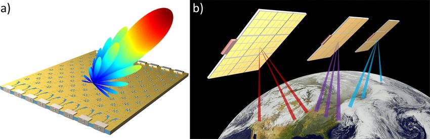
www.nature.com/scientificreports/
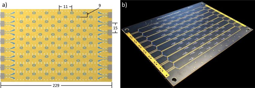
Figure 1. Nyquist metasurface antenna. (a) shows a Nyquist metasurface antenna forming a steered beam.
Nyquist metasurface antennas offer high performance from a low cost and thin platform, enabling the
construction of flat satellites. (b) shows a multi-satellite system using Nyquist metasurface antennas for satellite-
to-ground communications.
magnitude and phase response of a metamaterial element are linked through its resonance. Thus, the phase
and magnitude of a passive, radiating element cannot be controlled independently23,27. Despite this constrained
control, waveguide-fed metasurface antenna architectures have demonstrated high quality beamforming by
compensating for the reduced phase range by densely sampling the aperture (typically on the order of one-sixth
or less of the operating wavelength) and leveraging the phase advance of the guided w ave23,27.
In this paper, we describe the design of a metasurface antenna which relies on two key concepts: feed phase
diversity and varactors diodes. Feed phase diversity involves offsetting the initial wave in each waveguide com-
prising a metasurface antenna array; this strategy allows for the suppression of grating lobes without dense
element spacing27. Meanwhile, varactor diodes enable continuous phase tuning from metamaterial elements to
provide improved element tuning compared to PIN diodes. This design paradigm ultimately allows for meta-
material element placement at roughly half the wavelength of operation. Given that such sampling corresponds
to the Nyquist limit, we describe this device as a Nyquist metasurface antenna.
The Nyquist metasurface antenna offers electronic beamsteering not available with fixed beam metasurface
antennas17. Additionally, binary tuned metasurfaces can exhibit fast switching speeds, but they are difficult to
model (due to their dense element spacing, often required to be < /4)26. Meanwhile, liquid crystal metasur-
faces have demonstrated high quality beamforming, but suffer from slow switching speeds and high cost21. The
Nyquist metasurface antenna overcomes these challenges and limitations while demonstrating high performance
electronic beamforming.
In this work, we demonstrate a Nyquist metasurface antenna, fabricated using standard printed circuit board
(PCB) manufacturing. We show electronic beamforming in two (angular) dimensions while operating at 10
GHz. We show the Nyquist metasurface antenna has excellent performance, without incurring the high cost,
power consumption, and complexity of typical phased array antennas. Furthermore, the Nyquist metasurface
antenna can be readily redesigned to operate at higher or lower frequency bands and scaled to very large aper-
tures. An illustration of the antenna is shown in Fig. 1a. Figure 1b shows the potential to leverage the hardware
characteristics and performance associated with Nyquist metasurface antennas to deploy a constellation of flat
satellites for communication.
Methods
Metasurface antenna operation and challenges. To arrive at the design for the Nyquist metasurface
antenna, we addressed three major challenges associated with metasurface antennas: modeling the antenna, sup-
pressing grating lobes, and minimizing the coupling strength of each element. In this section, we describe these
challenges, which motivated our design, before briefly outlining our solutions. Further detail on the antenna
design is provided in the next section. By applying a cohesive design approach that addressed these issues simul-
taneously, we were able to realize a new design paradigm for high performance metasurface antennas.
First, ESAs often comprise electrically large structures with subwavelength features, rendering them difficult
to model with full-wave electromagnetic solvers, since the simulation domain tends to be extreme. A common
modeling approach is to simulate the radiation pattern of a single element in isolation. A composite antenna
array can then be predicted using array factor calculations to predict radiation patterns. These method works
well if the feed wave at every node is known and each element behaves the same.
In metasurface antennas, an approximate model is further necessary due to the small feature size of metamate-
rial radiators (often < /10). In our model, each metamaterial element is modeled as frequency-dependent point
dipole whose response can be measured from full-wave simulation (of one element) or experimental characteriza-
tion. Once the response of a single element has been determined, an overall antenna can be modeled as a series
of dipoles with array factor calculations. Additional consideration is given to the guided wave, which is modeled
using the complex scattering parameters of each element in conjunction with the analytic waveguide mode. This
overall approach enables the rapid simulation of different antenna layouts, tuning states, and f requencies28,29.
Scientific Reports | (2021) 11:4693 | https://doi.org/10.1038/s41598-021-83377-9 2
Vol:.(1234567890)
www.nature.com/scientificreports/
Figure 2. Varactor-tuned metamaterial element. The bottom left figure shows the dimensions of the
metamaterial radiators (in mm). The bottom right figure shows the magnitude and phase of the experimentally
characterized element response, measured at 9 GHz (red) and 10 GHz (blue), as the tuning sweeps from 0 to 5V.
Second, metasurface antennas are especially susceptible to unwanted grating lobes due to the lack of complete
control over phase and magnitude. In traditional antennas, grating lobes can arise when attempting to steer
beyond what the element spacing will allow. When sampled at the Nyquist limit, there is no upper bound on
steering, but sparser antennas can face this challenge. Metasurfaces, however, face grating lobe problems due to
their incomplete phase control—not their physical spacing. These metasurface-specific grating lobes arise because
phase-tuning metamaterial elements for beamforming creates an incidental, oscillating magnitude profile. Since
many elements are tuned to essentially non-radiating states, the effective element spacing becomes coarse, leading
to metasurface-specific grating lobes, independent of physical element s eparation27.
While previous metasurface designs have suppressed metasurface grating lobes using a combination of high
dielectric loading (to increase the effective waveguide index) and dense element spacing, here instead we seek
a design that allows a sparser sampling (close to half of a wavelength). We rely on the feed structure to provide
phase diversity at the excitation of each waveguide in our array. Such feed phase diversity suppresses grating
lobes in 2D metasurface arrays regardless of whether elements are spaced closer than the Nyquist l imit27. With
grating lobes suppressed by the feed structure, the elements can be positioned with spacing at or near the Nyquist
limit, even if hollow waveguides are used.
Third, as with leaky-wave antennas, the incident waveguide mode loses energy as it propagates through the
structure and excites the radiating metamaterial elements. If the elements are strongly coupled to the waveguide
mode, the waveguide mode attenuates quickly and much of the aperture no longer radiates significantly, result-
ing in a reduced effective aperture size. To avoid this effect, the coupling of the metamaterial elements can be
carefully reduced by offsetting them from the center of the waveguide (and further with tuning algorithms).
Offsetting the elements from the center and alternating sides of the waveguide reduces the coupling of the ele-
ments to the waveguide mode, allowing energy to reach elements far from the feed. Additionally, this approach
increases the distance between any two elements, reducing inter-element coupling, increasing the fidelity of the
modeling approach used in this work23,28,29.
Antenna subsystems. The composite 2D Nyquist metasurface antenna consists of an array of 1D wave-
guides; each 1D waveguide excites a linear array of metamaterial resonators. The waveguides are substrate inte-
grated waveguides (SIWs), which use a pair of via fences and metal layers to form a rectangular waveguide
within a PCB. The tunable element design, waveguide architecture, feed structure, and control system must all
be designed in an integrated fashion.
The metamaterial element design is a complementary electric-inductive-capacitive (cELC) resonator with
outer dimensions of 3.65 mm by 3.65 mm, as shown in Fig. 230. The cELC is used because it behaves electro-
magnetically as a polarizable magnetic dipole with a resonant polarizability, which can be electronically tuned.
Varactors placed across the capacitive gaps between the metamaterial and the surrounding waveguide’s upper
conductor provide a means of tuning the element’s capacitance, thereby tuning its resonance. The main considera-
tions for choosing the varactor are package size and self-resonant frequency. Given the relatively high frequency
range we are targeting, it is important that the self-resonant frequency be significantly higher than the operat-
ing frequencies so that the varactor does not add additional inductance or resistance to the circuit. MACOM
varactors (MAVR011020) were found to satisfy the requirements and selected for this design. A bias circuit is
integrated into the element design, with a control via extending from the center of the cELC through the SIW
core and through the bottom conductor of the waveguide to a layer used exclusively for biasing circuitry. Note
that the control via is located near the edge of the SIW to reduce its impact on the guided wave.
Applying voltage between 0 and 5 V changes the overall capacitance of the cELC and shifts the resonance of
the element from 8.5 to 10.7 GHz. At 10 GHz, the primary operating frequency of this antenna, this tunability
equates to 150◦ of phase tuning (the theoretical maximum phase tuning of a Lorentzian resonator is 180◦) and a
magnitude ratio of 4.5:1. The varactor-tuned metamaterial element is illustrated in Fig. 2, which also shows the
voltage-tuned polarizability, experimentally characterized at 10 GHz.
Substrate integrated waveguides were chosen for the metasurface antenna design as they are easily fabri-
cated using commercial, multilayer PCB technology (see Fig. 3c). SIWs behave as rectangular waveguides with
fields well-confined and described by well-known analytical e xpressions31. Rectangular waveguide modes are
particularly helpful in the context of a Nyquist metasurface antenna as most of the energy in the waveguide
Scientific Reports | (2021) 11:4693 | https://doi.org/10.1038/s41598-021-83377-9 3
Vol.:(0123456789)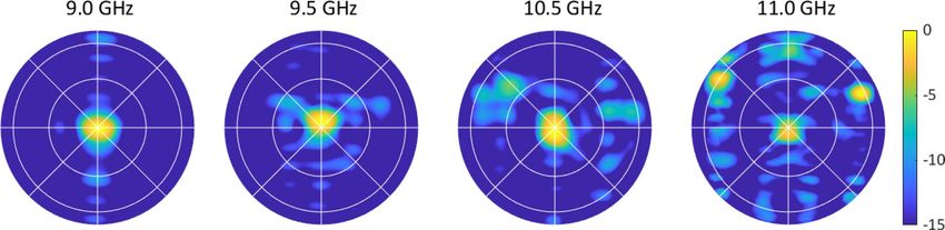
www.nature.com/scientificreports/
Figure 3. Waveguide structure underlying the Nyquist metasurface antenna. (a) shows an end launch
connector which excites a CPW. (b) shows the transition from CPW to the SIW shown in (c). (d) shows the RF
feed network which uses an eight-way power divider and passive phase shifters to apply the requisite feed phase
diversity.
Figure 4. Nyquist metasurface antenna layout, (a), with dimensions in mm. (b) Shows a picture of the antenna.
mode is concentrated towards the center. As a result, this waveguide structure allows for metamaterial elements
to be offset from the center of the waveguide to decrease coupling in order to allow sufficient energy to pass to
subsequent elements.
The Nyquist metasurface antenna layout consists of tiling the aperture area with adjacent SIWs; in this way,
a 2D aperture antenna comprises an array of eight 1D SIWs. Each SIW is 14 mm wide, with the SIWs separated
by 15 mm to provide space for via fences (see Fig. 4). To launch a wave into an SIW, we use end launch connec-
tors (shown in Fig. 3a). The end launch connector excites a grounded coplanar waveguide (CPW) mode, which
subsequently feeds the SIW through a CPW-to-SIW transition, optimized in CST Microwave Studio, and shown
in Fig. 3b32. The components of the waveguide structure are detailed graphically in Fig. 3. A 50 terminator at
the end of each waveguide minimizes reflection by absorbing the remaining energy.
One of the challenges mentioned above is suppressing metasurface-specific grating lobes. Metasurface anten-
nas are tuned with passive components to avoid active phase shifters, sacrificing complete phase control for a
continuous but limited range of phase tuning (less than half that of a phase shifter). The impact of this limitation
can be understood when considering the formation of a beam steered to some angle, which requires an aperture
field distribution whose phase profile linearly increases as a function of position. For metasurface antennas,
simply attempting to match this phase distribution leads to approximately half of the elements being unused;
these elements are set to non-radiating states since the targeted phase values lie outside the available phase space.
This phenomenon leads to an oscillating magnitude profile due to the repeating collections of elements tuned to
non-radiating states. In a recent work, it has been found that if multiple waveguides are used, each excited with
a distinct phase, the grating lobes can be cancelled out. The combination of this feed diversity with optimized
tuning strategies can lead to a 2D metasurface antenna that fully suppresses metasurface grating lobes without
relying on dense element s pacing27.
A phase diverse feed mechanism is an essential component of such a metasurface antenna, as pictured in
Fig. 3. The functions of such a feed mechanism are twofold. First, the feed layer must divide the power from
a single incoming RF source according to the number of waveguides present in the device. Second, the feed
mechanism must apply the requisite phase shift for grating lobe suppression. While these functions could be
realized with two devices, a mechanism such as a PCB-integrated feed layer could do both and thereby simplify
antenna construction. Overall, this feed layer would act as a corporate feed with individual delay lines, integrated
within the antenna PCB. While this approach would ultimately be preferred, its implementation exceeds the
scope of this work.
Scientific Reports | (2021) 11:4693 | https://doi.org/10.1038/s41598-021-83377-9 4
Vol:.(1234567890)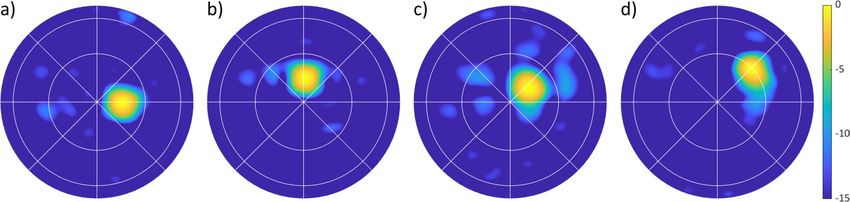
www.nature.com/scientificreports/
Rather than working through complex feed design, we chose for expediency to use an eight-way power divider
connected to a series of passive, mechanically set phase shifters to create the requisite phase diversity. From top
to bottom, the phase shifters provide a feed phase of [270◦ , 180◦ , 90◦ , 0◦ , 0◦ , 90◦ , 180◦ , 270◦ ], respectively, result-
ing in the feed waves shown in Fig. 3d. The phase shifters have been mechanically set for operation at 10 GHz.
A more elegant waveguide feed structure could operate over a larger bandwidth, but such a structure is beyond
the scope of this work.
Modeling and tuning. An accurate model of a metasurface antenna is necessary to determine the tuning of each
element needed to form desired radiation patterns such as steerable, directive beams. For electrically large anten-
nas, typical simulators that numerically solve Maxwell’s equations require extremely large numbers of unknowns
resulting in prohibitively long simulation times and memory storage requirements. As a means of dealing with
the multiscale modeling problem, we abstract each metamaterial element as a frequency-dependent, infinitesi-
mal, polarizable dipole, as mentioned above28,29. Metamaterial elements are resonant structures. If the element
is suitably smaller than the operational wavelength, it can be modeled as a polarizable dipole as a function of
geometry and material p arameters23. The radiated fields can then be quickly and easily determined by summing
the radiated fields from each of the effective dipoles. During the design process, the polarizability of one element
was determined from a full-wave simulation of one element, requiring a minimal simulation domain. The dipole
moment representing each metamaterial element (η) can be calculated as the product of the incident magnetic
field (H) and the element’s polarizability (α)29.
η = Hα (1)
The magnetic polarizability of a cELC element follows a Lorentzian response as a function of the excitation
frequency (ω ), resonant frequency (ω0), coupling factor (F), and damping (γ ).
Fω2
α= 2 (2)
ω0 − ω2 + jωγ
These parameters are difficult to estimate analytically but can be readily obtained from full-wave simulations of
single metamaterial elements25,29. Though useful for prediction and design, experimental characterization must
ultimately be used to determine α accurately for a given metasurface structure, since fabrication variances and
varactor properties lead to unavoidable uncertainties for key parameters.
After fabrication, experimental characterization determined the exact value of α for the metamaterial ele-
ment. A separate PCB was fabricated alongside the metasurface antenna to facilitate waveguide and element
characterization. This characterization board includes thru-reflect-line (TRL) characterization channels as well
as a channel with a single element. The TRL channels provide a means of de-embedding an individual element’s
scattering parameters to isolate them from the surrounding waveguide structure33,34. The scattering parameters
can then be used to calculate the element’s polarizability as a function of frequency and tuning v oltage25,35,36.
jab
α=− (1 + S11 − S21 ) (3)
β
Here, a and b are the horizontal and vertical dimensions of the waveguide, respectively, and β is the wavenumber
of the SIW (determined experimentally). Figure 2 shows the element response at 10 GHz, showing the tunable
α. Polarizability extraction in this way is further detailed in25,35.
After measuring or modeling α, the guided wave, H, must be modeled. The waveguide mode can be readily
calculated analytically as a function of the geometry and material properties of the waveguide. To validate the
analytic model of H, the characterization board described above was also used to experimentally measure β of
an empty waveguide.
When a waveguide is populated with several metamaterial elements, scattering from each element decays
the guided wave’s energy and applies a phase shift. To account for the impact of each element’s scattering on the
guided wave, complex S21 is extracted along with α during the element characterization. The field at element n,
Hn, can then be determined approximately as a function of each element’s tuning and position.
Hn = H0 e−jβxn S21,n (4)
n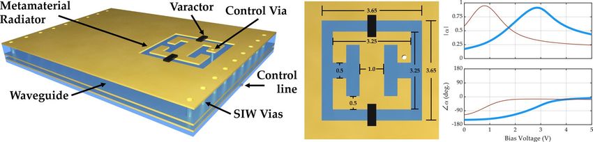
www.nature.com/scientificreports/
ηdesired,nm = ejk(xn sin θ0 cos φ0 +ym sin θ0 sin φ0 ) (5)
Here, k is the free space wavenumber, θ0 and φ0 are the angles to which the beam is steered, and xn and ym are
the position4,5,23. A magnitude taper can also be applied in order to change the side lobe levels and other antenna
metrics, but such considerations are beyond the scope of this investigation. Equation 5 is the starting point to
determine the tuning state of a metasurface antenna, in which we have control over the polarizability of each
element. The product of the polarizability and the incident magnetic field equate to the dipole moment (Eq. 1),
which functions in exactly the same manner as the antenna weights in an array factor calculation. For a given
metamaterial element to have the value ηdesired,nm, the element’s tunable polarizability must be chosen so as to
counteract the phase advance of the guided wave and apply the phase prescribed by Eq. (5). In a traditional
phased array antenna, this process would be done by simply mapping the phase of each element to that of
Eq. (5). Here, we opt for a metasurface-specific tuning strategy—Euclidean modulation—which maps each ele-
ment’s polarizability by minimizing the Euclidean norm between the desired and available values of αnm (rather
than minimizing the phase difference). Using this mapping strategy leads to a compromise between the phase
and magnitude response of a metamaterial element, resulting in highly directive beamforming while avoiding
unnecessary efficiency loss.
In a metasurface antenna, as the guided wave traverses the waveguide, energy is gradually leaked into free
space, creating a natural exponential magnitude taper. The decay rate of the taper is related to the tuning state
of each element, the average coupling strength, the dielectric loss, and the element spacing. This decay can limit
performance in two major ways. If the decay is too fast, a portion of the aperture will be unused, limiting aperture
size and thus directivity. If the decay is too slow, unused energy will be terminated at the end of the waveguide,
reducing efficiency. To balance these factors, the decay of the guided wave must be deliberately controlled with
tuning and geometry. A balance between these concerns can be met by augmenting Euclidean modulation with a
scale factor. To use scaled Euclidean modulation, αdesired,nm is divided by a scale factor (A) as αdesired,nm /A before
minimizing applying Euclidean modulation.
α
desired
min − αavailable (6)
A
Nyquist metasurface antenna design. The final metasurface antenna design comprises eight adjacent wave-
guides that cover a 2D area. Each waveguide includes an integrated waveguide transition show in Fig. 3. A
coaxial-fed end launch connector excites a wave into a grounded coplanar waveguide, which then transitions to
a SIW. Each waveguide contains 12 individually tunable metamaterial elements, spaced 11 mm apart along the
waveguides. As indicated in Fig. 2, each element is located 4.75 mm away from the center of the waveguide to
reduce coupling with the guided wave. Additionally, elements alternate sides down the waveguide to increase
the distance between elements, reducing the inter-element coupling. The overall layout is illustrated in Fig. 4.
The antenna is fabricated on a four-layer PCB using Rogers 4003C (ǫ = 3.38, δ = 0.0027). The top two layers
contain the waveguides and metamaterial elements, while the bottom two layers contain control circuitry and
components. The elements are controlled using 8-bit, 8 channel digital to analog converters (DACs), which pro-
vide an independent bias for each element from 0 to 5V. A PC running Matlab was interfaced with an Arduino
microcontroller to control the antenna. Radial stubs are connected to each control line to decouple the DC and
RF signals. The antenna was designed to operate over a bandwidth of 9.6 to 10 GHz.
The overall Nyquist metasurface antenna uses 96 elements to cover a radiating area of 12 cm by 12 cm. The
sparse layout has not been presented in previous metasurface antenna designs due to concerns with grating lobes.
But by combining feed diversity (for grating lobe suppression) with continuous phase tunable metamaterial ele-
ments (using varactors), such a Nyquist metasurface antenna can avoid the high dielectrics and dense element
spacing associated with prior waveguide-fed metasurface antenna designs. The sparse layout of weakly coupled
elements has the additional advantage that the analytical dipole model does not need to consider interactions
among elements. Though such modeling can be performed using coupled dipoles, simulation and optimization
are much more straightforward if each element can be treated as an independent dipole.
Results
The main design goal for the metasurface antenna described in this work was to demonstrate the generation of
a directive beam that could be steered in azimuth and elevation over a defined bandwidth. Efficiency, sidelobe
level, and all other metrics were secondary considerations, though they could readily be addressed in future
designs. After the characterization board was used to measure a single element and an empty waveguide, an
experimental model was used when modeling the antenna. For the metamaterial element, the effective polariz-
ability was extracted as a function of frequency and tuning voltage. For the feed structure and empty waveguides,
the experimentally characterized waveguide mode was used in place of the analytically modeled H (including
the phase diversity present within H0). Scaled Euclidean modulation optimization (described in Eq. 6) was then
applied to determine the tuning state for each element as a function of steered angle. After determining each
element’s tuning state, the appropriate bias voltage was then applied to each element in the antenna.
To characterize the radiation pattern of the antenna, near-field scan measurements were taken at an independ-
ent facility with an anechoic chamber (Wireless Research Center, Wake Forest, NC). The near-field measurements
were then propagated to the far-field to determine the antenna’s radiation p attern37. For all results in this section,
the operating frequency was 10 GHz unless otherwise stated.
Scientific Reports | (2021) 11:4693 | https://doi.org/10.1038/s41598-021-83377-9 6
Vol:.(1234567890)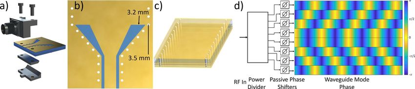
www.nature.com/scientificreports/

                                  Figure 5.  Broadside farfield radiation pattern (measured in normalized directivity) of the Nyquist metasurface
                                  antenna at 10 GHz. Farfields in all figures are in the u − v plane, where u = cos θ cos φ and v = cos θ sin φ, with
                                  gridlines showing θ at 30◦ and 60◦ and φ from 0◦ to 360◦ in 45◦ increments.

                                  Figure 6.  Each plot shows the normalized directivity (dB) radiation pattern from the Nyquist metasurface
                                  antenna. (a) is steered in azimuth to 15◦; (b) is steered in elevation to 15◦. (c,d) show steering in both azimuth
                                  and elevation to (10◦, 10◦) and (30◦, 30◦), respectively.

                                      The first demonstration with the metasurface antenna was to generate a broadside beam. The measured
                                  farfield pattern for broadside beam generation is shown in Fig. 5. Cross sections in azimuth and elevation show
                                  the beam pattern and sidelobe level. From the 2D plot, it can be seen that there are no significant grating lobes.
                                      The antenna was also tuned to generate a beam steered in azimuth and elevation. Figure 6a shows the beam
                                  steered to 15◦ in azimuth; Fig. 6b shows the beam steered to 15◦ in elevation. Figure 6c,d show beams steered
                                  diagonally. Still, no grating lobes appear in the 2D beam patterns, indicating that using feed phase diversity to
                                  suppress grating lobes is functioning as intended.
                                      Next, steering performance was more rigorously measured. In azimuth, a beam was steered continuously
                                  from −60◦ to 60◦, shown in Fig. 7a,b. In elevation, a beam was steered continuously from −75◦ to 75◦, as shown
                                  in Fig. 7c,d. In both directions, the steering accuracy is shown to the right of the cross section plots. The deter-
                                  mined steering ranges are ±50◦ in azimuth and ±70◦ in elevation. Videos of the antenna steering in azimuth/
                                  elevation and also around in circles can be seen in the supplemental information.
                                      To explore the operational bandwidth of the antenna, we generated a broadside beam at various frequencies
                                  near 10 GHz. Our target bandwidth of operation was 9.6–10 GHz. Note that performance away from 10 GHz
                                  may be degraded due to the feed structure, which was mechanically set for operation at 10 GHz. From 9 to 11
                                  GHz, a new tuning state was applied and the radiation pattern was measured. Figure 8 shows that the antenna
                                  can generate a broadside beam across a large frequency range, from 9.00 to 10.75 GHz.
                                      Though azimuth steering, elevation steering, and operational bandwidth were the primary performance met-
                                  rics, other metrics were measured. The maximum efficiency of the antenna was measured to be 11% (recorded
                                  for broadside beam generation). Polarization isolation was measured to be 30 dB. It should also be noted that
                                  all of the tuning states used here were generated by the dipole model described above, without modification to
                                  account for fabrication tolerance, mutual coupling, or other effects.
                                      Metrics such as efficiency, gain, and sidelobe level were also measured for broadside beam generation and
                                  across a steered range of −45◦ to 45◦ in azimuth and elevation. These results are reported in Fig. 9, which show
                                  that the antenna realizes a sidelobe level of − 13 dB at broadside. Across those steering ranges, the sidelobes
                                  remain below − 9 dB. It should also be noted some tuning parameters (such as A in (6)) have been optimized
                                  for broadside beam generation, so results at other steered angles may be worse than at broadside. Optimizing
                                  model/tuning parameters or individual element tuning states for all steered angles could improve performance,
                                  but such studies are beyond the scope of this work.

Scientific Reports |   (2021) 11:4693 |                https://doi.org/10.1038/s41598-021-83377-9                                                      7

                                                                                                                                                Vol.:(0123456789)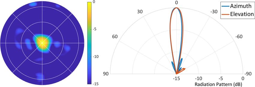
www.nature.com/scientificreports/

                                            Figure 7.  The radiation pattern of the metasurface antenna steering in azimuth (φ = 0◦) and elevation
                                            (φ = 90◦). (a) shows azimuth cross sections steered from −60◦ to 60◦ in 15◦ increments. (b) shows the azimuth
                                            steering accuracy (with the dashed line showing the goal), indicating that the antenna can accurately steer
                                            from −50◦ to 50◦. (c) shows elevation cross sections steered from −75◦ to 75◦ in 15◦ increments. (d) shows the
                                            elevation steering accuracy (with the dashed line showing the goal), indicating that the antenna can accurately
                                            steer from −70◦ to 70◦.

                                            Figure 8.  Frequency coverage of the Nyquist metasurface antenna, determined by broadside beam formation.
                                            For each measurement, a new tuning state has been applied. Plots show radiation pattern (dB).

                                            Figure 9.  Antenna metrics as a function of azimuth and elevation steering.

                                               To explore the capabilities of the antenna further, we generated multiple beams simultaneously. To determine
                                            the tuning state for multiple beams, we averaged the αdesired for each beam and then applied scaled Euclidean
                                            modulation. Still, with this relatively rudimentary effort, two beams could be formed simultaneously in azimuth
                                            and in elevation. This experiment yielded the beam patterns shown in Fig. 10.

          Scientific Reports |   (2021) 11:4693 |               https://doi.org/10.1038/s41598-021-83377-9                                                    8

Vol:.(1234567890)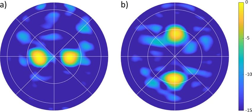
www.nature.com/scientificreports/

                                 Figure 10.  Multiple-beam formation with the Nyquist metasurface antenna, measured in normalized
                                 directivity. (a) shows two beams in azimuth (steered to ±15◦); (b) shows two beams in elevation (steered to
                                 ±25◦).

                                  Discussion
                                  Dynamically reconfigurable antennas play a critical role in many critical technologies, including radar, micro-
                                  wave and imaging, communications, synthetic aperture radar, and many others. Yet, capabilities in many of
                                  these fields have been hindered by the high cost and complexity of electronically scanned antenna systems,
                                  which have relied predominantly on active components. Metasurface antennas have offered an alternative to
                                  traditional ESAs, providing nearly equivalent performance with passive components, avoiding the phase shift-
                                  ers and amplifiers in conventional systems. Where previous systems required dense element spacing and lossy
                                  dielectrics, the Nyquist metasurface antenna approach avoids these requirements. The ability to form metasurface
                                  antennas using lightweight PCB components unlocks the potential for use in mobile or power-limited environ-
                                  ments. Further, Nyquist metasurfaces can be built with hollow waveguides, allowing for future antennas to be
                                  highly efficient. The sparse layout presented here scales far better—both in cost and power draw—to extremely
                                  large apertures such as those that might be needed in massive MIMO systems, providing a realistic path towards
                                  satellite constellations for Earth observation and wireless communications.

                                  Received: 2 October 2020; Accepted: 27 January 2021

                                  References
                                   1. Soumekh, M. Synthetic Aperture Radar Signal Processing Vol. 7 (Wiley, New York, 1999).
                                   2. Ager, T. P. An introduction to synthetic aperture radar imaging. Oceanography 26, 20–33 (2013).
                                   3. Ochs, S. & Pitz, W. The terrasar-x and tandem-x satellites. In 2007 3rd International Conference on Recent Advances in Space Tech-
                                      nologies 294–298 (IEEE, 2007).
                                   4. Hansen, R. C. Phased Array Antennas Vol. 213 (Wiley, New York, 2009).
                                   5. Mailloux, R. J. Phased Array Atenna Handbook (Artech House, Norwood, 2017).
                                   6. Mittermayer, J., Wollstadt, S., Prats, P., Scheiber, R. & Koppe, W. Staring spotlight imaging with terrasar-x. In 2012 IEEE Interna-
                                      tional Geoscience and Remote Sensing Symposium, 1606–1609 (IEEE, New York, 2012).
                                   7. National Academies of Sciences, Engineering, and Medicine. Thriving on our Changing Planet: A Decadal Strategy for Earth
                                      Observation from Space (National Academies Press, 2019).
                                   8. Soumekh, M. Fourier Array Imaging (Prentice-Hall Inc, Upper Saddle River, 1994).
                                   9. Rosen, P. A. et al. The nasa-isro sar mission-an international space partnership for science and societal benefit. In 2015 IEEE Radar
                                      Conference (RadarCon), 1610–1613 (IEEE, 2015).
                                  10. Lim, S., Caloz, C. & Itoh, T. Metamaterial-based electronically controlled transmission-line structure as a novel leaky-wave antenna
                                      with tunable radiation angle and beamwidth. IEEE Trans. Microwave Tech. 52, 2678–2690 (2004).
                                  11. Martinez-Ros, A. J., Gómez-Tornero, J. L. & Goussetis, G. Holographic pattern synthesis with modulated substrate integrated
                                      waveguide line-source leaky-wave antennas. IEEE Trans. Antennas Propag. 61, 3466–3474 (2013).
                                  12. Fong, B. H., Colburn, J. S., Ottusch, J. J., Visher, J. L. & Sievenpiper, D. F. Scalar and tensor holographic artificial impedance surfaces.
                                      IEEE Trans. Antennas Propag. 58, 3212–3221 (2010).
                                  13. Sievenpiper, D., Schaffner, J., Lee, J. & Livingston, S. A steerable leaky-wave antenna using a tunable impedance ground plane.
                                      IEEE Antennas Wirel. Propag. Lett. 1, 179–182 (2002).
                                  14. Gregoire, D., Colburn, J., Patel, A., Quarfoth, R. & Sievenpiper, D. An electronically-steerable artificial-impedance-surface antenna.
                                      In 2014 IEEE Antennas and Propagation Society International Symposium (APSURSI), 551–552 (IEEE, New York, 2014).
                                  15. Epstein, A., Wong, J. P. & Eleftheriades, G. V. Cavity-excited huygens’ metasurface antennas for near-unity aperture illumination
                                      efficiency from arbitrarily large apertures. Nat. Commun. 7, 1–10 (2016).
                                  16. Patel, A. M. & Grbic, A. A printed leaky-wave antenna based on a sinusoidally-modulated reactance surface. IEEE Trans. Antennas
                                      Propag. 59, 2087–2096 (2011).
                                  17. Minatti, G. et al. Modulated metasurface antennas for space: Synthesis, analysis and realizations. IEEE Trans. Antennas Propag.
                                      63, 1288–1300 (2014).
                                  18. Smith, D. R., Padilla, W. J., Vier, D., Nemat-Nasser, S. C. & Schultz, S. Composite medium with simultaneously negative perme-
                                      ability and permittivity. Phys. Rev. Lett. 84, 4184 (2000).
                                  19. Smith, D., Vier, D., Koschny, T. & Soukoulis, C. Electromagnetic parameter retrieval from inhomogeneous metamaterials. Phys.
                                      Rev. E 71, 036617 (2005).
                                  20. Li, L. et al. Electromagnetic reprogrammable coding-metasurface holograms. Nat. Commun. 8, 1–7 (2017).
                                  21. Johnson, M. C., Brunton, S. L., Kundtz, N. B. & Kutz, J. N. Sidelobe canceling for reconfigurable holographic metamaterial antenna.
                                      IEEE Trans. Antennas Propag. 63, 1881–1886 (2015).
                                  22. Hunt, J. et al. Metamaterial apertures for computational imaging. Science 339, 310–313 (2013).

Scientific Reports |   (2021) 11:4693 |                     https://doi.org/10.1038/s41598-021-83377-9                                                                          9

                                                                                                                                                                         Vol.:(0123456789)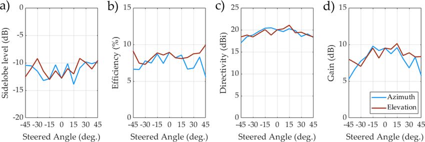
www.nature.com/scientificreports/
23. Smith, D. R., Yurduseven, O., Mancera, L. P., Bowen, P. & Kundtz, N. B. Analysis of a waveguide-fed metasurface antenna. Phys.
Rev. Appl. 8, 054048 (2017).
24. Sleasman, T., Boyarsky, M., Imani, M. F., Gollub, J. N. & Smith, D. R. Design considerations for a dynamic metamaterial aperture
for computational imaging at microwave frequencies. JOSA B 33, 1098–1111 (2016).
25. Boyarsky, M. et al. Synthetic aperture radar with dynamic metasurface antennas: A conceptual development. JOSA A 34, A22–A36
(2017).
26. Sleasman, T. et al. Experimental synthetic aperture radar with dynamic metasurfaces. IEEE Trans. Antennas Propag. 65, 6864–6877
(2017).
27. Boyarsky, M., Imani, M. F. & Smith, D. R. Grating lobe suppression in metasurface antenna arrays with a waveguide feed layer.
Opt. Express 28, 23991–24004 (2020).
28. Hunt, J. et al. Metamaterial microwave holographic imaging system. JOSA A 31, 2109–2119 (2014).
29. Lipworth, G. et al. Comprehensive simulation platform for a metamaterial imaging system. Appl. Opt. 54, 9343–9353 (2015).
30. Sleasman, T. et al. Waveguide-fed tunable metamaterial element for dynamic apertures. IEEE Antennas Wireless Propag. Lett. 15,
606–609 (2015).
31. Xu, F. & Wu, K. Guided-wave and leakage characteristics of substrate integrated waveguide. IEEE Trans. Microwave Theory Tech.
53, 66–73 (2005).
32. Taringou, F., Dousset, D., Bornemann, J. & Wu, K. Broadband cpw feed for millimeter-wave siw-based antipodal linearly tapered
slot antennas. IEEE Trans. Antennas Propag. 61, 1756–1762 (2012).
33. Engen, G. F. & Hoer, C. A. Thru-reflect-line: An improved technique for calibrating the dual six-port automatic network analyzer.
IEEE Trans. Microwave Theory Tech. 27, 987–993 (1979).
34. Eul, H.-J. & Schiek, B. Thru-match-reflect: One result of a rigorous theory for de-embedding and network analyzer calibration. In
1988 18th European Microwave Conference, 909–914 (IEEE, New York, 1988).
35. Scher, A. D. & Kuester, E. F. Extracting the bulk effective parameters of a metamaterial via the scattering from a single planar array
of particles. Metamaterials 3, 44–55 (2009).
36. Pulido-Mancera, L., Bowen, P. T., Imani, M. F., Kundtz, N. & Smith, D. Polarizability extraction of complementary metamaterial
elements in waveguides for aperture modeling. Phys. Rev. B 96, 235402 (2017).
37. Johnson, R. C., Ecker, H. A. & Hollis, J. S. Determination of far-field antenna patterns from near-field measurements. Proc. IEEE
61, 1668–1694 (1973).
Acknowledgements
This work was supported by the Air Force Office of Scientific Research (AFOSR), grant number FA9550-18-1-
0187. The authors would like to thank Russell Hannigan, K. Parker Trofatter, and Dr. Daniel Marks.
Author contributions
M.B. designed and simulated the antenna with input from T.S. T.S. designed the control circuitry. M.B. and M.F.I.
designed the feed structure. M.B. wrote the control software and took measurements, with help from J.N.G. M.B.
prepared the manuscript, with input from all other authors.
Competing interests
The authors declare no competing interests.
Additional information
Supplementary Information The online version contains supplementary material available at https://doi.
org/10.1038/s41598-021-83377-9.
Correspondence and requests for materials should be addressed to M.B.
Reprints and permissions information is available at www.nature.com/reprints.
Publisher’s note Springer Nature remains neutral with regard to jurisdictional claims in published maps and
institutional affiliations.
Open Access This article is licensed under a Creative Commons Attribution 4.0 International
License, which permits use, sharing, adaptation, distribution and reproduction in any medium or
format, as long as you give appropriate credit to the original author(s) and the source, provide a link to the
Creative Commons licence, and indicate if changes were made. The images or other third party material in this
article are included in the article’s Creative Commons licence, unless indicated otherwise in a credit line to the
material. If material is not included in the article’s Creative Commons licence and your intended use is not
permitted by statutory regulation or exceeds the permitted use, you will need to obtain permission directly from
the copyright holder. To view a copy of this licence, visit http://creativecommons.org/licenses/by/4.0/.
© The Author(s) 2021
Scientific Reports | (2021) 11:4693 | https://doi.org/10.1038/s41598-021-83377-9 10
Vol:.(1234567890)You can also read