SUNSHINE COAST REGIONAL DISTRICT ANTENNA SYSTEMS INSTALLATION AND TOWER REENFORCEMENT PROJECT TELUS CO TOWER - GIBSONS, BC VERSION 1.0 - Telus ...
←
→
Page content transcription
If your browser does not render page correctly, please read the page content below
SUNSHINE COAST REGIONAL DISTRICT

                   ANTENNA SYSTEMS INSTALLATION
                 AND TOWER REENFORCEMENT PROJECT

                      TELUS CO TOWER – GIBSONS, BC

                                    VERSION 1.0

REVISION HISTORY

 Ver      Date                       By                                   Remarks
 1.0   2021 05 20    M. Kapustianyk, P.Eng.               Final Version
                     Planetworks Consulting Corporation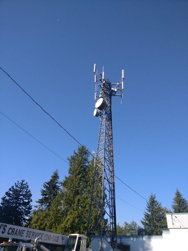
SUNSHINE COAST REGIONAL DISTRICT
                             ANTENNA SYSTEM INSTALLATION, RACK INSTALLATION
                                   AND TOWER REINFORCEMENT PROJECT

                                                TELUS CO TOWER – GIBSONS, BC

                                                           TABLE OF CONTENTS

1.0     General ............................................................................................................................................. 2
  1.1      Overview ....................................................................................................................................... 2
2.0     Schedule .......................................................................................................................................... 3
3.0     Installation and Integration Services ............................................................................................ 4
  3.2      Codes and Standards ................................................................................................................... 4
  3.3      Delivery Point ................................................................................................................................ 5
  3.4      Project Management ..................................................................................................................... 5
4.0     Technical Specifications and Guidelines ..................................................................................... 6
  4.1      Antenna Mounting ......................................................................................................................... 6
  4.2      Transmission Lines ....................................................................................................................... 6
  4.3      Transmission Line Supports .......................................................................................................... 7
  4.4      Grounding (Tower) ........................................................................................................................ 7
  4.5      Connectors .................................................................................................................................... 7
  4.6      Lightning Arrestors (LPU) .............................................................................................................. 7
5.0     System As-Built Documentation ................................................................................................... 8
6.0     Appendix A - Bill of Materials ........................................................................................................ 9
7.0     Appendix B – Site Pictures ......................................................................................................... 13
8.0     Appendix C – LTE Antenna and Mount Specifications ............................................................ 18
9.0     Appendix D – VHF Antenna Specifications ............................................................................... 19
10.0    Appendix E – 900MHz Antenna Specifications ......................................................................... 20

V1.0                                                                    Page 1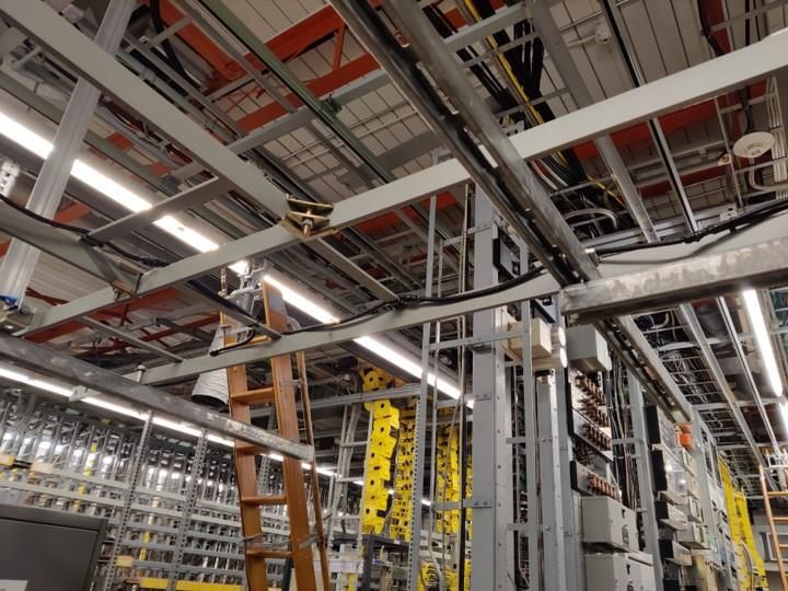
SUNSHINE COAST REGIONAL DISTRICT
                     ANTENNA SYSTEM INSTALLATION, RACK INSTALLATION
                           AND TOWER REINFORCEMENT PROJECT

                                TELUS CO TOWER – GIBSONS, BC

1.0    GENERAL
       1.1   Overview

             1.1.1     This document defines the scope of a Contract to provide antenna systems supply
                       and installation, tower reinforcement and electrical grounding services at the 30m
                       TELUS Communications Inc. (TELUS) CO Tower located at 692 North Road,
                       Gibsons, BC (49.408228N, 123.512902W). This work is required to facilitate a
                       collocation of antenna systems belonging to the Sunshine Coast Regional District
                       (SCRD). Site pictures are in the Appendices.

             1.1.1     The work requires the reinforcement of tower splice plates prior to antenna system
                       installation. All installation and tower reinforcement details are provided in the
                       separate drawing set, “Telecon Design Antenna and Reinforcement Installation
                       Drawing Package for TELUS CO Tower BC0310”.
             1.1.2     The work requires the supply, installation, and testing of antenna systems at the
                       tower, including:

                                   1. Comprod 874F-70 VHF antenna extended above the tower top
                                      (34m),
                                   2. SCALA KATHREIN PR900 paragrid antenna at 30.5m
                                   3. LTE Antenna, Phoenix Contact, part #2702273 mounting near
                                      roof height near/on the site building.

             1.1.2     A summary Bill of Materials matrix is provided in Appendix A detailing the items
                       required at this site. The Contractor must confirm that this Bill of Materials is
                       accurate for the project.
             1.1.3     The Contractor shall provide the following services related to the delivery of these
                       services:

                                   1. Procure and assemble all equipment as required by these
                                      specifications,
                                   2. Pack, ship and deliver all components to the tower site,
                                   3. Provide required tower reinforcements as per the attached
                                      drawings,
                                   4. Install, test, and align the antenna systems for proper functioning,
                                   5. Provide proper grounding systems to be connected to existing
                                      tower and site grounding systems,
                                   6. Provide red-lined marked up drawings for Telecon Engineering to
                                      aid in drawing updates and confirmation of proper construction
                                      services,
                                   7. Manage the project through a single point of contact. The
                                      Contractor should provide project management as required to
                                      maintain the schedule and quality of work within the
                                      Specifications, and
                                   8. Provide a two-year warranty per the contracted terms and
                                      conditions.

V1.0                                            Page 2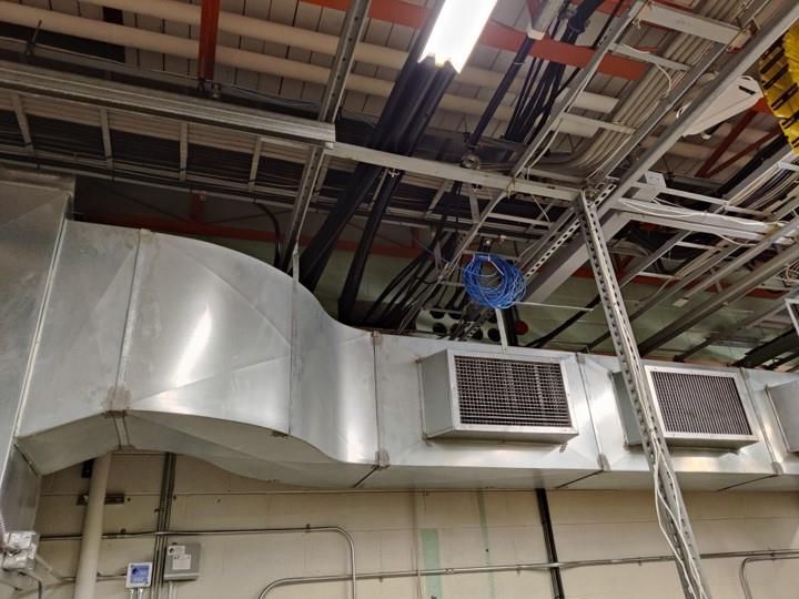
SUNSHINE COAST REGIONAL DISTRICT
                    ANTENNA SYSTEM INSTALLATION, RACK INSTALLATION
                          AND TOWER REINFORCEMENT PROJECT

                              TELUS CO TOWER – GIBSONS, BC

2.0    SCHEDULE
            2.1.1     The project target dates are shown in the table below. Provide the proposed
                      schedule in the right-most column.

                                                                Target            Proposed
                                 Description                  Completion        Completion Date

                      Last day for Questions                  4 June 2021             N/A

                      Tender Bid Close                       11 June 2021             N/A

                      Contract Award                         25 June 2021             N/A

                      Equipment Delivery                      4 Aug 2021

                      Antenna system installations and
                                                              11 Aug 2021
                      tower reinforcement

                      Documentation                           18 Aug 2021

V1.0                                           Page 3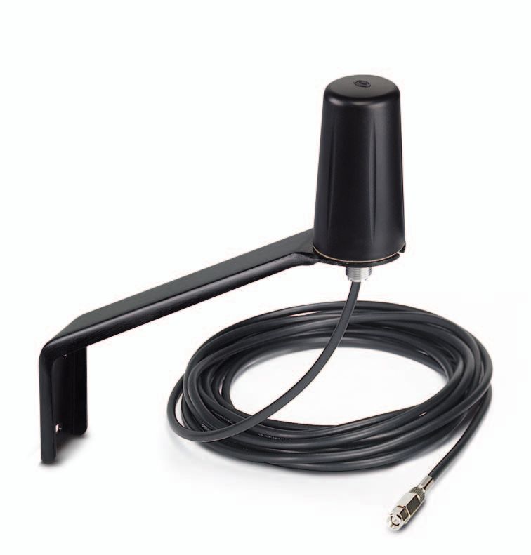
SUNSHINE COAST REGIONAL DISTRICT
                     ANTENNA SYSTEM INSTALLATION, RACK INSTALLATION
                           AND TOWER REINFORCEMENT PROJECT

                                 TELUS CO TOWER – GIBSONS, BC

3.0    INSTALLATION AND INTEGRATION SERVICES
             3.1.1     The Contractor shall be currently approved by TELUS to carryout antenna
                       installation and tower reinforcement work on this tower. This will be confirmed with
                       TELUS prior to any contract award.
             3.1.2     The Contractor shall use experienced and certified tower riggers and technical
                       support staff to plan and carry out all fabrication, installation, and testing.
             3.1.3     The Contractor shall use industry standard installation procedures and practices
                       to ensure that logical, professional, and reliable installations are provided for this
                       contract. Contractors must be aware and ensure that work will be consistent with
                       any TELUS installation policies, procedures, and practices.
             3.1.4     The Contractor shall coordinate all work to the tower and the antenna installations
                       directly with TELUS, always informing the Sunshine Coast Regional District of
                       work progress and areas of concern.
             3.1.5     The Contractor shall take care ensuring that the following is carried out during any
                       implementation or other on-site work:
                                   1. A structured and documented safety plan is provided, and all
                                      safety policies adhered to as per guidelines set by TELUS,
                                   2. All equipment is securely installed,
                                   3. All cabling and equipment are appropriately labelled and are
                                      consistent with all approved drawings,
                                   4. All equipment, antenna system and antenna mounts/towers are
                                      grounded to TELUS grounding points. All grounding systems to
                                      meet local, provincial, and national electrical codes.
                                   5. No unsafe physical or electrical conditions are left once fieldwork
                                      is complete,
                                   6. All sites are left thoroughly cleaned, vacuumed and orderly at the
                                      end of each day of installation work, and
                                   7. No unconventional or ad hoc integration or mounting is used.

       3.2   Codes and Standards
             3.2.1     The equipment and all integration items shall meet relevant codes and standards
                       from the following organizations that are in force on the date of issue of this
                       document.
                                   1.   Canadian Standards Association (CSA)
                                   2.   Innovation, Science and Economic Development Canada (ISED)
                                   3.   Canadian Electrical Code (CEC)
                                   4.   Electronic Industries Association (EIA)
                                   5.   Telecommunications Industry Association (TIA)

V1.0                                             Page 4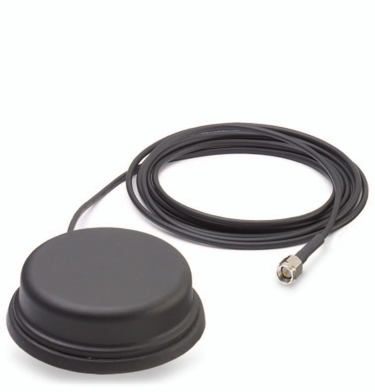
SUNSHINE COAST REGIONAL DISTRICT
                      ANTENNA SYSTEM INSTALLATION, RACK INSTALLATION
                            AND TOWER REINFORCEMENT PROJECT

                                 TELUS CO TOWER – GIBSONS, BC

              3.2.2     Unless specifically noted otherwise elsewhere, in the event of conflict or
                        discrepancy between any requirements of the above codes and standards, the
                        more stringent requirement will govern.
              3.2.3     The Contractor shall apply for and administer all permits required for this project.
                        This includes electrical permits, development permits, building permits, etc., if
                        required.

       3.3   Delivery Point
              3.3.1     Equipment shall be delivered to the tower site for installation. Documentation shall
                        be delivered to TELUS, Telecon Design, and the Sunshine Coast Regional District.

       3.4   Project Management
              3.4.1     The Contractor should use risk management procedures to identify and quantify
                        risks in cost and delay terms, assess their probability, and devise and implement
                        strategies to avoid or minimize the impact of serious risks.

V1.0                                              Page 5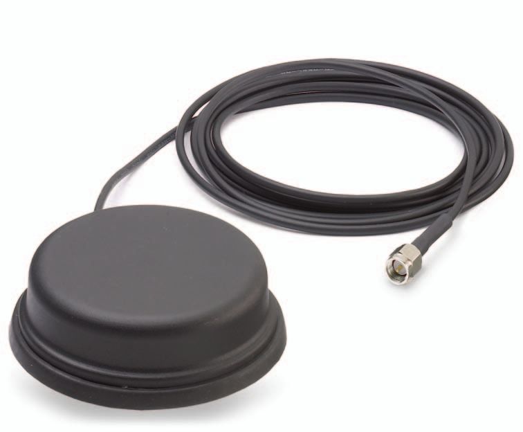
SUNSHINE COAST REGIONAL DISTRICT
                     ANTENNA SYSTEM INSTALLATION, RACK INSTALLATION
                           AND TOWER REINFORCEMENT PROJECT

                                 TELUS CO TOWER – GIBSONS, BC

4.0    TECHNICAL SPECIFICATIONS AND GUIDELINES

       4.1   Antenna Mounting
             4.1.1     Supply and install antenna mounts for the two tower antenna locations as designed
                       by Telecon Design.       .
             4.1.2     Supply and install LTE antenna mount near the building cable entry. Final location
                       to be specified by the site owner. The appendix provides details for the antenna
                       and mounting.

       4.2   Transmission Lines
             4.2.1     The Contractor shall exercise extreme care and good installation practices in the
                       handling, transporting, hoisting, and installing of transmission lines and antennas.
             4.2.2     Transmission lines and antennas shall be installed in the positions indicated.
             4.2.3     The Contractor shall make and waterproof all outdoor connections.
             4.2.4     For tower antennas use AVA5-50 (approx. 40m length) transmission line from
                       antenna connector through to the Lightning Protection Unit (LPU) connection. Use
                       LMR600-FR Fire retardant FT4 rated transmission line from the LPU through to
                       the equipment rack location (approx. 20m length).
             4.2.5     All transmission line lengths shall be verified on-site prior to cutting cable.
             4.2.6     All transmission lines from the antenna connection through to the lightning arrestor
                       shall be one continuous piece. Inter-run couplings are not acceptable.
             4.2.7     Each transmission line shall be routed straight and true from bend to bend. All
                       bends shall be smoothly formed with uniform curvature, and the bend radius shall
                       not be less than the minimum bend radius specified by the cable manufacturer.
             4.2.8     All transmission line runs shall be routed and secured in a neat manner which will
                       protect the cables from damage and will not present obstruction hazards. Final
                       routing will be at the discretion of TELUS.
             4.2.9     The Contractor shall install the connectors on the transmission lines at each end
                       of the transmission line.
             4.2.10 Installation of connectors, and the making and sealing of connections, shall
                    conform in all respects to the manufacturer recommended procedures.
             4.2.11 All exposed connections shall be sealed with suitable tape to be waterproof.
                    Waterproofing shall extend to completely enclose both the cable to connector and
                    connector to connector junctions.
             4.2.12 Coax transmission line metal tags with punched identification labels shall be
                    supplied and installed. Tags shall be located at each coax connector on the AVA5-
                    50 and LMR600 lines.
             4.2.13 Existing building entry points shall be used.

V1.0                                             Page 6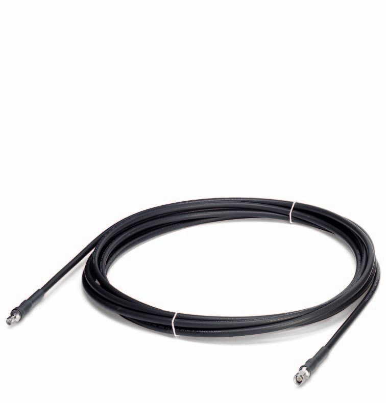
SUNSHINE COAST REGIONAL DISTRICT
                      ANTENNA SYSTEM INSTALLATION, RACK INSTALLATION
                            AND TOWER REINFORCEMENT PROJECT

                                 TELUS CO TOWER – GIBSONS, BC

       4.3   Transmission Line Supports
              4.3.1     Transmission lines shall be laterally supported between the antenna and
                        equipment building with stainless steel clamps or hangers of the type specified by
                        the manufacturer. The existing cable bridge is to be used.
              4.3.2     Each transmission line shall be supported at every point where it crosses a
                        transmission line bracket and at every support under a cable bridge by a clamp
                        specified above. Clamp spacing shall not exceed manufacturer’s
                        recommendations.

       4.4   Grounding (Tower)
              4.4.1     Grounding kits shall be installed and bonded to the coax feed line and grounding
                        point at the top of the tower, lower end of the transmission line run on the tower
                        and immediately outside the building entry point.
              4.4.2     Grounding kits shall be of the type specified by the transmission line manufacturer
                        and be installed and waterproofed in a manner which conforms to manufacturer
                        recommendations.
              4.4.3     Each ground strap shall be attached to the Tower with a 3/8” stainless steel bolt
                        and shall not interfere with the installation of future transmission lines.

       4.5   Connectors
              4.5.1     All connectors shall be high grade compression fit models, typically N type and
                        7/16 DIN (see Bill of Materials). In-line connector adapters shall not be used.
              4.5.2     The make and model of connector shall conform to the recommendations by the
                        transmission line manufacturer.

       4.6   Lightning Arrestors (LPU)
              4.6.1     The LPU’s shall be installed inside the building within 300mm from the building
                        entry point. LPU’s shall be grounded to the exterior ground bar at the building entry
                        point.
              4.6.2     A Polyphaser lightning arrestor shall be installed on each cable run and mounted
                        and grounded to the ground bar. Supply Polyphaser IS-B50LN-C2 for the 900MHz
                        antenna system, the Polyphaser VHF50HN for the VHF antenna, and the
                        Polyphaser TSX-NFF for the LTE modem antenna.

V1.0                                              Page 7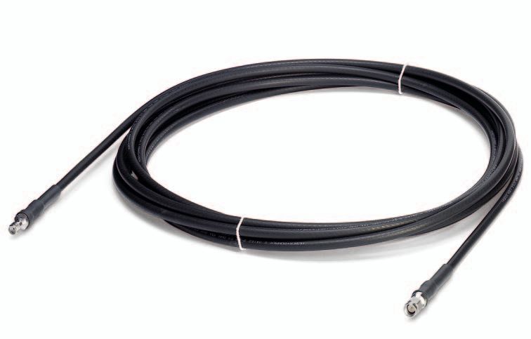
SUNSHINE COAST REGIONAL DISTRICT
                    ANTENNA SYSTEM INSTALLATION, RACK INSTALLATION
                          AND TOWER REINFORCEMENT PROJECT

                               TELUS CO TOWER – GIBSONS, BC

5.0    SYSTEM AS-BUILT DOCUMENTATION
            5.1.1     The Contractor should provide as-built documentation for this installation in PDF
                      format and hardcopy. As a minimum, this documentation should include the
                      following:
                           5.1.1.1 Contact Information for the purposes of support, including primary
                                   service manager phone number, cell number, email address and
                                   address,
                           5.1.1.2 Redline as-built drawings complete with cable identifiers,
                           5.1.1.3 Equipment list including the manufacture, model, and serial number,
                           5.1.1.4 Digital pictures of antenna systems installation at all key points,
                                   including the connectors, cable entry, ground connection and
                                   antenna mounting.
                           5.1.1.5 Copies of antenna system sweeps with graphical curves in VSWR or
                                   Return Loss , supplied for the following sub bands:
                                    (i)      VHF – 136 to 174MHz
                                    (ii)     900MHz - to 930-950MHz
                                    (iii)    LTE – 750 to 2000MHz
                           5.1.1.6 Copies of factory test sheets for antenna equipment supplied,
            5.1.2     The hardcopy documentation should be securely bound into convenient size
                      binder and provided with durable covers. Covers and spines should include
                      documentation titles. Provide two (2) copies in binders with coversheet and
                      labelled page tabs separating sections.
            5.1.3     The softcopy documentation should be provided on Flash Memory/USB memory
                      drive. PDF copies should be in a single file or minimum number of files with each
                      file bookmarked for ease of navigation. The information should be complete, with
                      minimum or no need for links to web sites that may in future break.

                                            END OF SECTION

V1.0                                            Page 8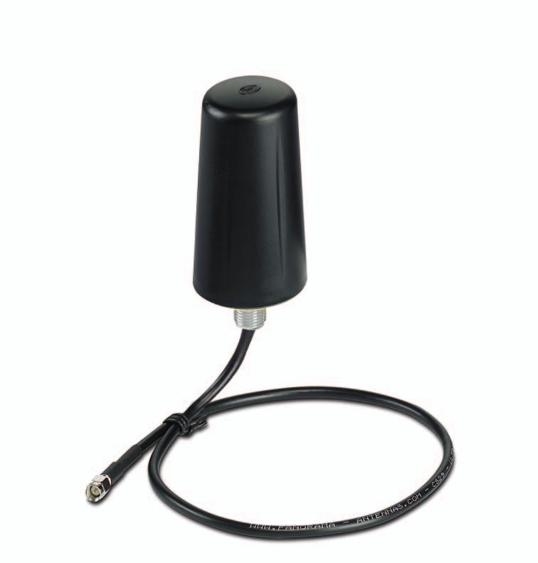
SUNSHINE COAST REGIONAL DISTRICT
                 ANTENNA SYSTEM INSTALLATION, RACK INSTALLATION
                       AND TOWER REINFORCEMENT PROJECT

                           TELUS CO TOWER – GIBSONS, BC

6.0    APPENDIX A - BILL OF MATERIALS

V1.0                                    Page 9
SUNSHINE COAST REGIONAL DISTRICT
ANTENNA SYSTEM INSTALLATION, RACK INSTALLATION
AND TOWER REINFORCEMENT PROJECT
TELUS CO TOWER – GIBSONS, BC
QUANTITY
& UNIT OF EXTENDED
DESCRIPTION ISSUE UNIT PRICE PRICE
Tower reinforcement material and labour, as per
1 1 Each
Telecon design specifications.
Antenna mounts for 874F-70 antenna, as per
2 1 Each
Telecon design specifications.
Antenna mounts for Kathrein PR-900 paragrid
3 1 Each
antenna, as per Telecon design specifications.
Comprod 874F-70 1/2 wave, VHF 4 Exposed
Dipoles, Heavy Duty, TOP MOUNT, PIM rated DIN
4 1 Each
connector, 138-174MHz and appropriate mounting
clamps
Kathrein PR-900 paragrid antenna, 896-960MHz,
5 1 Each
with MKPX-xx mounting kit (Contractor select xx)
Phoenix Contact LTE Antenna/ Wall mount 5M,
6 1 Each
part #2702273
7 SMA(f) to N(m) adapter (LTE antenna to LPU) 1 Each
8 SMA(m) to N(f) adapter (jumper to LTE modem) 1 Each
9 AVA5-50 50ohm feedline (one continuous length) 100m
10 AVA5-50 cable prep tool, part # CPT-78U 1 Each
11 AVA5-50 Coupling Nut Torque Tool, part #244377 1 Each
12 AVA5-50 coax hangers LOT
V1.0 Page 10SUNSHINE COAST REGIONAL DISTRICT
ANTENNA SYSTEM INSTALLATION, RACK INSTALLATION
AND TOWER REINFORCEMENT PROJECT
TELUS CO TOWER – GIBSONS, BC
QUANTITY
& UNIT OF EXTENDED
DESCRIPTION ISSUE UNIT PRICE PRICE
13 AVA5-50 Hoist Grip 2 Each
DIN-female compression connector for AVA5-50,
14 1 Each
part # AL5DF-PSA (one antenna connection)
N-male connector for AVA5-50, part # AL5NM-PSA
15 (one antenna connection and two LPU 3 Each
connections)
16 AVA5-50 Coupling Nut Torque Tool, part #244379 1 Each
17 Ground kits for AVA5-50, part #SG78-12B2U 6 Each
Polyphaser Lightning Arrestor for VHF band (N-
18 female both ends), part #VHF50HN (includes 2 Each
spare)
Polyphaser Lightning Arrestor for 900MHz band (N-
19 female both ends), part #IS-B50LN-C2 (includes 2 Each
spare)
Polyphaser Lightning Arrestor for LTE band (N-
20 2 Each
female both ends), part #TSX-NFF (includes spare)
LMR-600-FR indoor/outdoor fire retardant 50ohm
21 80m
feedline (one continuous length)
N-male compression connector for LMR600, part #
22 Comp-NM-600 (three for LPU connections, three 6 Each
for radio equipment connections)
V1.0 Page 11SUNSHINE COAST REGIONAL DISTRICT
ANTENNA SYSTEM INSTALLATION, RACK INSTALLATION
AND TOWER REINFORCEMENT PROJECT
TELUS CO TOWER – GIBSONS, BC
QUANTITY
& UNIT OF EXTENDED
DESCRIPTION ISSUE UNIT PRICE PRICE
Antenna System, antenna mounts and grounding
23 installation services, including tools and equipment Lump Sum
required to complete the project.
24 Travel Costs Lump Sum
25 Project Management Services Lump Sum
Other - describe fully here:
26
Subtotal
GST (5%)
PST (7%) $
Total $
V1.0 Page 12SUNSHINE COAST REGIONAL DISTRICT
ANTENNA SYSTEM INSTALLATION, RACK INSTALLATION
AND TOWER REINFORCEMENT PROJECT
TELUS CO TOWER – GIBSONS, BC
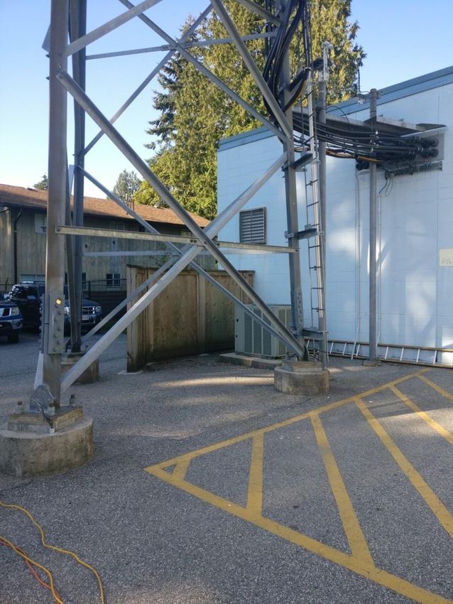
7.0 APPENDIX B – SITE PICTURES
V1.0 Page 13SUNSHINE COAST REGIONAL DISTRICT
ANTENNA SYSTEM INSTALLATION, RACK INSTALLATION
AND TOWER REINFORCEMENT PROJECT
TELUS CO TOWER – GIBSONS, BC
V1.0 Page 14SUNSHINE COAST REGIONAL DISTRICT
ANTENNA SYSTEM INSTALLATION, RACK INSTALLATION
AND TOWER REINFORCEMENT PROJECT
TELUS CO TOWER – GIBSONS, BC
V1.0 Page 15SUNSHINE COAST REGIONAL DISTRICT
ANTENNA SYSTEM INSTALLATION, RACK INSTALLATION
AND TOWER REINFORCEMENT PROJECT
TELUS CO TOWER – GIBSONS, BC
V1.0 Page 16SUNSHINE COAST REGIONAL DISTRICT
ANTENNA SYSTEM INSTALLATION, RACK INSTALLATION
AND TOWER REINFORCEMENT PROJECT
TELUS CO TOWER – GIBSONS, BC
V1.0 Page 17SUNSHINE COAST REGIONAL DISTRICT
ANTENNA SYSTEM INSTALLATION, RACK INSTALLATION
AND TOWER REINFORCEMENT PROJECT
TELUS CO TOWER – GIBSONS, BC
8.0 APPENDIX C – LTE ANTENNA AND MOUNT SPECIFICATIONS
V1.0 Page 18TC ANT MOBILE...
Mobile antennas and antenna cables
Data sheet
106760_en_04 © PHOENIX CONTACT 2019-06-05
1 Description
This data sheet describes the accessories for mobile com-
munications products. All mobile communications products
from Phoenix Contact have an SMA antenna connection.
Therefore, you can use the following antennas:
Designation Order No. Mounting Image
Mounting directly on device, installation not visi-
PSI-GSM-STUB-ANT 2313342
ble from the outside in plastic control cabinets
Wall or mast mounting with mounting bracket,
TC ANT MOBILE WALL 5M 2702273 indoor or outdoor installation,
suitable for LTE/4G
Wall mounting with mounting bracket,
TC ANT MOBILE WALL 0,5M 2702274 indoor or outdoor installation,
suitable for LTE/4G
PSI-GSM/UMTS-QB-ANT 2313371 Mounting on the control cabinet,
TC ANT MOBILE/GPS 2903590 with 2 m antenna cable
Mounting on the control cabinet,
TC ANT MOBILE CABINET 10M 1046361
with 10 m antenna cable
Furthermore, antenna cables are also available for extending by 5 meters or 10 meters.
Make sure you always use the latest documentation.
It can be downloaded at phoenixcontact.net/products.TC ANT MOBILE...
2 Table of contents
1 Description..................................................................................................................................1
2 Table of contents ........................................................................................................................2
3 Ordering data..............................................................................................................................3
4 PSI-GSM-STUB-ANT .................................................................................................................4
4.1 Dimensions ....................................................................................................................................................4
4.2 Mounting ........................................................................................................................................................4
5 TC ANT MOBILE WALL 5M and TC ANT MOBILE WALL 0,5M .................................................5
5.1 Safety notes ...................................................................................................................................................6
5.2 Mounting with mounting bracket.....................................................................................................................6
5.3 Mounting on a surface ....................................................................................................................................7
5.4 Laying the antenna cable ...............................................................................................................................7
6 PSI-GSM/UMTS-QB-ANT and TC ANT MOBILE/GPS ...............................................................8
6.1 Mounting ........................................................................................................................................................9
7 TC ANT MOBILE CABINET 10M ..............................................................................................10
7.1 Dimensions ..................................................................................................................................................10
7.2 Mounting ......................................................................................................................................................11
8 Antenna cables .........................................................................................................................12
106760_en_04 PHOENIX CONTACT 2 / 12TC ANT MOBILE... 3 Ordering data Antennas Type Order No. Pcs./Pkt. GSM antenna for direct mounting on the device, angled PSI-GSM-STUB-ANT 2313342 1 antenna plug (90°, SMA circular connector). The antenna is suitable for installation not visible from the outside in plastic control cabinets. Multiband mobile antenna with mounting bracket for outdoor TC ANT MOBILE WALL 5M 2702273 1 installation, 5 m antenna cable with SMA circular connector, suitable for LTE/4G Multiband mobile antenna for wall mounting, 0.5 m antenna TC ANT MOBILE WALL 0,5 2702274 1 cable, with SMA circular connector, suitable for LTE/4G M GSM-UMTS antenna, with omnidirectional characteristics, PSI-GSM/UMTS-QB-ANT 2313371 1 2 m antenna cable with SMA circular connector, for mount- ing on the control cabinet Combined mobile GPS antenna with omnidirectional charac- TC ANT MOBILE/GPS 2903590 1 teristics, 2 m antenna cable with SMA circular connector (GSM/UMTS) and R-SMA circular connector (GPS) for mounting on the control cabinet Mobile antenna for mounting on the control cabinet, TC ANT MOBILE CABINET 1046361 1 10 m antenna cable with SMA circular connector 10M Antenna cables Type Order No. Pcs./Pkt. Mobile antenna cable, 5 m in length, PSI-CAB-GSM/UMTS- 5M 2900980 1 SMA (male) -> SMA (female), 50 ohm impedance Mobile antenna cable, 10 m in length, PSI-CAB-GSM/UMTS-10M 2900981 1 SMA (male) -> SMA (female), 50 ohm impedance 106760_en_04 PHOENIX CONTACT 3 / 12
TC ANT MOBILE...

4       PSI-GSM-STUB-ANT
The antenna is suitable for installation not visible from the outside in plastic control cabinets.

PSI-GSM-STUB-ANT                                                  2313342
Frequency range                                                   900 MHz / 1800 MHz
Standing wave ratio (VSWR in a 50 ohm system)                     Typical
TC ANT MOBILE...

5       TC ANT MOBILE WALL 5M and TC ANT MOBILE WALL 0,5M

                                         TC ANT MOBILE WALL 5M                      TC ANT MOBILE WALL 0,5M
                                                  2702273                              2702274
Frequency range                                      700 MHz / 800 MHz / 850 MHz / 900 MHz /
                                                   1700 MHz / 1800 MHz / 1900 MHz / 2100 MHz /
                                                              2600 MHz / 3600 MHz
Standing wave ratio (VSWR in a
TC ANT MOBILE...
5.1 Safety notes TC ANT MOBILE WALL 5M, wall or mast mounting
WARNING: Risk of death due to electric • Wall mounting: Mount the mounting bracket. Use M5
shock machine screws or self-tapping screws. You can use
the bracket as a drilling template (see Figure 5).
Parts of the antenna are electrically conductive.
Mast mounting: Mount the mounting bracket using a
Contact with live cables can lead to death or seri-
worm drive clip with a maximum width of 14 mm (see
ous injuries.
Figure 6).
– The antenna and the mast must not be in the
• If you wish to mount the antenna permanently, you can
vicinity of live cables during installation or re-
also use the adhesive surface on the bottom side of the
moval.
antenna. In this case, make sure that the surface of the
– If there is risk of lightning strikes: Make sure bracket is clean and dry. Pull the foil off the adhesive
that the antenna is mounted and grounded by surface. Press the antenna firmly onto the bracket.
qualified specialist personnel in accordance
• Fix the antenna firmly to the mounting bracket using the
with generally recognized technical regula-
nut and washer supplied.
tions.
WARNING: Fall hazard 47
Make sure that the mounting location can be
reached safely with the available equipment.
84
CAUTION: High frequency
Ø14,3
Mount the antenna in such a way that persons will
135
not be within a radius of 30 centimeters during op-
eration.
38
5
5.2 Mounting with mounting bracket 16 205
15,3
37,2
Selecting the mounting location
Figure 5 TC ANT MOBILE WALL 5M, wall mounting
With the mounting bracket, you can mount the antenna onto
a wall. Alternatively, you can also mount the
TC ANT MOBILE WALL 5M to a mast.
Mount the antenna vertically with the antenna cable facing
downwards. Note that there must be a gap of at least
30 centimeters between the antenna and metallic parts or
surfaces. Select the mounting location so that the antenna
cable can be routed safely to the device.
If you use screws, make sure that there is sufficient space
behind the mounting area. Only use the mounting bracket
supplied. Other brackets could impair the performance of
the antenna.
Select an antenna position providing good wireless network
conditions.
If you use two antennas on a 4G mobile communications
device (MIMO), allow at least 20 centimeters distance
between the antennas. This way, you will achieve optimum
reception.
Figure 6 TC ANT MOBILE WALL 5M, mast mounting
106760_en_04 PHOENIX CONTACT 6 / 12TC ANT MOBILE...
TC ANT MOBILE WALL 0,5M, wall mounting 5.3 Mounting on a surface
• Mount the mounting bracket. Use M5 machine screws
Selecting the mounting location
or self-tapping screws. You can use the bracket as a
drilling template. For optimum performance, mount the antenna on a suffi-
• If you wish to mount the antenna permanently, you can ciently dimensioned electrically conductive grounding plate.
also use the adhesive surface on the bottom side of the Plates with a thickness of 1 mm ... 13 mm and a diameter of
antenna. In this case, make sure that the surface of the at least 200 mm are suitable. Note that there must be a gap
bracket is clean and dry. Pull the foil off the adhesive of at least 30 centimeters between the antenna and other
surface. Press the antenna firmly onto the bracket. metallic parts.
• Fix the antenna firmly to the mounting bracket using the Make sure that there is sufficient space underneath the
nut and washer supplied. mounting surface.
If you use two antennas on a 4G mobile communications
Ø48 device (MIMO), allow at least 20 centimeters distance
between the antennas. This way, you will achieve optimum
reception.
Mounting
85
• Cover the plate around the hole to be drilled in order to
protect the surface.
• Drill a small hole and enlarge it to a diameter of 14 mm.
Make sure that you do not damage any parts under-
neath the drill hole with the drill.
48
Ø4,5
• Clean the surface surrounding the drill hole and remove
82
any chipping. Remove paint and primer on the bottom
side of the plate. Sufficient electrical contact must be
24
ensured via the washer and the nut.
34,5 60
• Remove the washer and the nut from the antenna. Pull
48
the foil off the adhesive surface.
Figure 7 TC ANT MOBILE WALL 0,5M, wall mounting • Feed the antenna cable through the drill hole.
• Press the antenna firmly onto the plate.
• Secure the antenna underneath the plate using the
washer and nut. Tighten the nut.
5.4 Laying the antenna cable
• Route the antenna cable to the device.
• Do not route the cable in the immediate vicinity of other
cables.
• Make sure that moving parts do not knock against the
antenna cable.
106760_en_04 PHOENIX CONTACT 7 / 12TC ANT MOBILE...
6 PSI-GSM/UMTS-QB-ANT and TC ANT MOBILE/GPS
PSI-GSM/UMTS-QB-ANT TC ANT MOBILE/GPS
2313371 2903590
Frequency range 850 MHz / 900 MHz / 1800 MHz / 1900 MHz / 2100 MHz
Gain (depending on frequency and
connection assembly)
800 MHz / 900 MHz 5 dBi 5 dBi
1800 MHz / 1900 MHz 3 dBi 3 dBi
2100 MHz 1 dBi 1 dBi
GPS - 25 dBi
Standing wave ratio mobile networkTC ANT MOBILE...
6.1 Mounting
Figure 8 Antenna for mounting on the control cabinet
• Drill a hole with a diameter of 16.5 mm into the top of the
control cabinet.
• When mounting, please note that the antenna has a
diameter of 76 mm. The cable has a length of 2 meters.
• Secure the antenna using the washer and nut provided.
Figure 9 Mounting
106760_en_04 PHOENIX CONTACT 9 / 12TC ANT MOBILE... 7 TC ANT MOBILE CABINET 10M This antenna is especially suited for mounting on the control cabinet. A 10 m antenna cable is supplied as standard. TC ANT MOBILE CABINET 10M 1046361 Frequency range 850 MHz / 900 MHz / 1800 MHz / 1900 MHz / 2100 MHz Standing wave ratio (VSWR)
TC ANT MOBILE...

7.2      Mounting

Figure 11      Antenna for mounting on the control cabinet

•     Drill a hole with a diameter of 18.9 mm into the top of the
      control cabinet.
•     When mounting, please note that the antenna has a
      diameter of 77.4 mm. The cable has a length of
      10 meters.
•     Secure the antenna using the washer and nut provided.

Figure 12      Mounting

106760_en_04                                                        PHOENIX CONTACT   11 / 12
TC ANT MOBILE...
8 Antenna cables
Each antenna cable is equipped with an SMA connector and socket. You can simply mount them without an additional
adapter between the antenna and device.
PSI-CAB-GSM/UMTS- 5M PSI-CAB-GSM/UMTS-10M
2900980 2900981
Length 5 meters 10 meters
Cable attenuation
850 MHz 1.15 dB 2.3 dB
900 MHz 1.2 dB 2.4 dB
1800 MHz 1.75 dB 3.5 dB
2100 MHz 1.95 dB 3.9 dB
2600 MHz 2.2 dB 4.4 dB
Impedance 50 Ω
Frequency range 850 MHz / 900 MHz / 1800 MHz / 1900 MHz / 2100 MHz / 2600 MHz
Connection SMA (male) - SMA (female)
Bending radius, permanent 82 mm
Outside diameter 5.5 mm
Material of outer sheath LSFH
Ambient temperature range -40°C ... 85°C
We recommend using only one of these cables in
applications. Otherwise attenuation is too high.
Figure 13 Antenna cables
106760_en_04 PHOENIX CONTACT GmbH & Co. KG • Flachsmarktstraße 8 • 32825 Blomberg • Germany 12 / 12
phoenixcontact.comSUNSHINE COAST REGIONAL DISTRICT
ANTENNA SYSTEM INSTALLATION, RACK INSTALLATION
AND TOWER REINFORCEMENT PROJECT
TELUS CO TOWER – GIBSONS, BC
9.0 APPENDIX D – VHF ANTENNA SPECIFICATIONS
V1.0 Page 19BASE STATION ANTENNAS
VHF EXPOSED DIPOLES 138-174 MHz
870 Series VHF Exposed Dipoles
The 870 Series VHF Exposed Dipoles are available in 1, 2, 4, 8, dipole and dual dipole configurations. All our antennas can
be completely customized to your particular applications. Our antennas can be black anodized, adjustable or fixed, side
mount or top mount, and heavy-duty versions are available.
• Each antenna is offered in a 1/4, 3/8, or 1/2 wave spacing versions.
• The 87XA-70 has external cabling and a field-adjustable pattern.
• The 87XF-70 has internal cabling and fixed dipole-mast spacing.
• Heavy-duty versions are available. Please contact our Technical Support team for consultation.
Electrical Specifications 871F-70 872F-70 874F-70
Frequency Range, MHz 138-174 138-174 138-174
Nominal Gain, dBd 2.0-2.5 5.0-5.5 8.0-8.5
Number of Dipoles 1 2 4
Bandwidth 1.5:1 VSWR, MHz 36 36 36
Polarization Vertical Vertical Vertical
Pattern Offset / bi Offset / bi Offset / bi
Power Rating, Watts 200 450 450
Nominal Impedance, Ohms 50 50 50
Lightning Protection DC Ground DC Ground DC Ground
Standard Termination Type N Type N Type N
Male Male Male
Mechanical Specifications 871F-70 872F-70 874F-70
872F-70
Length, in (mm) 78 (1981) 162 (3200) 246 (6248)
Width (1/2 Wave Spacing), in (mm) 40 (1016) 40 (1016) 40 (1016)
Weight, lbs. (kg) 13 (6) 24 (10.8) 67 (30)
Rated Wind Velocity, No Ice, mph (km/h) 170 (274) 150 (241) 110 (177)
Rated Wind Velocity, 0.5” (13mm) ice, mph (km/h) 145 (233) 135 (217) 85 (137)
Lateral Thrust @ 100 mph, wind, lbs. (N) 45 (199) 92 (407) 206 (914)
Bending Moment @ top clamp: 100 mph, ft.*lb 18 (24) 205 (278) 1440 (1953)
(N*m)
Projected Area, ft² (m²) 1.7 (0.16) 3.5 (0.33) 7.7 (0.72)
Mounting Information Mast O.D. (mm) 1.9" (48) 2.4" (61) 2.9" (73)
* See next page for ordering information (page 3) *
Tel: US 1.877.825.2007 / CAN 1.800.603.1454
1
www.comprodcom.com Email: sales@comprodcom.com
Fax: 1.800.554.1033BASE STATION ANTENNAS
VHF EXPOSED DIPOLES 138-174 MHz
0 0 0
0 0
0
330 30 330 30 330 30
-5 -5 -5
dB dB dB
-10 -10 -10
300 -15
60 300 -15
60 300 60
-15
-20 -20 -20
-25 -25 -25
270 90 270 90 270 90
240 120 240 120 240 120
210 150 210 150 210 150
180
871F-70 180 180
Quarter-wave Spacing Horizontal Half-wave Spacing Horizontal Half-wave Spacing Vertical
0
0 0
0
330 30 0
0
-5
330 30 330 30
dB -5
-5
dB
dB
-10
-10
-10
300 -15
60 300 60 300 60
-15 -15
-20 -20 -20
-25 -25 -25
270 90 270 90 270 90
240 120 240 120 240 120
210 150 210 150
210 150
872F-70 180 180
180
Quarter-wave Spacing Horizontal Half-wave Spacing Horizontal Half-wave Spacing Vertical
0 0 0
0 0
0
330 30 330 30 330 30
-5 -5 -5
dB dB dB
-10 -10 -10
300 -15
60 300 60 300 60
-15 -15
-20 -20 -20
-25 -25 -25
270 90 270 90 270 90
240 120 240 120 240 120
210 150 210 150 210 150
180 180 180
Quarter-wave Spacing Horizontal Half-wave Spacing Horizontal Half-wave Spacing Vertical
874F-70
Tel: US 1.877.825.2007 / CAN 1.800.603.1454
2
www.comprodcom.com Email: sales@comprodcom.com
Fax: 1.800.554.1033BASE STATION ANTENNAS
VHF EXPOSED DIPOLES 138-174 MHz
Order Information Adjustable Heavy Duty Side Mount Top Mount Black Anodized
871F-70 871A-70 871F-70-HD 871F-70-SM 871F-70-TM 871F-70-HDB
872F-70 872A-70 872F-70-HD 872F-70-SM 872F-70-TM 872F-70-HDB
874F-70 874A-70 874F-70-HD 874F-70-SM 874F-70-TM 874F-70-HDB
3Tel: US 1.877.825.2007 / CAN 1.800.603.1454
www.comprodcom.com Email: sales@comprodcom.com
Fax: 1.800.554.1033SUNSHINE COAST REGIONAL DISTRICT
ANTENNA SYSTEM INSTALLATION, RACK INSTALLATION
AND TOWER REINFORCEMENT PROJECT
TELUS CO TOWER – GIBSONS, BC
10.0 APPENDIX E – 900MHZ ANTENNA SPECIFICATIONS
V1.0 Page 20PR-900
High-Gain Half-Parabolic Antenna
The Scala Paraflector® is a high-gain half-parabolic
antenna used in broadcast and communications
systems around the world.
High front-to-back ratio for point-to-point relay system
applications, as well as GSM cellular repeaters and
MAS and ISM systems.
Fabricated from seamless drawn aluminum tubing and
extruded pipe and heavy aluminum castings, gold
anodized for corrosion protection, plus stainless steel
hardware and fastenings. Foam filled broadband feed
assembly requires no pressurization and can be easily
replaced if necessary.
6SHFLILFDWLRQV
Frequency range 890—960 MHz
Gain 16 dBd (18.15 dBi)
Impedance 50 ohms
VSWR 23 dB
Maximum input power 100 watts (at 50°C)
H-plane beamwidth 12 degrees (half-power)
E-plane beamwidth 24 degrees (half-power)
Connector N female
Weight 38 lb (17.2 kg)
Dimensions 68 x 36 x 18 inches
(1727 x 914 x 457 mm)
Wind load at 93 mph (150 kph) H-plane
Front / side 134 lbf / 72 lbf Horizontal pattern — V-polarization
Vertical pattern — H-polarization
(594 N) / (320 N)
Wind survival rating* 100 mph (160 kph)
Shipping dimensions 40 x 36 x 7 inches
(1016 x 914 x 178 mm)
Shipping weight 47 lb (21.3 kg)
Mounting Mounting kits available for masts of
2.375 to 4.5 inch (60 to 114 mm) OD.
* Mechanical design is based on environmental conditions as stipulated in
TIA-222-G-2 (December 2009) and/or ETS 300 019-1-4 which include
the static mechanical load imposed on an antenna by wind at maximum
velocity. Contact KBU for further details.
PARAFLECTOR is a registered trademark of Kathrein Broadcast USA. E-plane
Horizontal pattern — H-polarization
Vertical pattern — V-polarization
30016 subject to alteration
PR-900 Page 1 of 2
All specifications are subject to change without notice.
The latest specifications are available at www.kathrein-bca.com
Kathrein Broadcast USA Greenway Plaza II, 2400 Lakeside Blvd., Suite 650, Richardson TX 75082
Phone: 541.879.2300 Email: support-usa@kathrein-bca.comPR-900
High-Gain Half-Parabolic Antenna
68 inches
(1727 mm)
36 inches 18 inches
(914 mm) (457 mm)
Rear view Top view
Paraflector Screen Dimensions
(shown vertically polarized)
2x MKPX-2 Mounting Kit
Mounting options
Model Description
MKPX-2 (2x) Mounting kit for 2.375 inch (60 mm) OD mast
MKPX-9 Mounting kit for 2.875 inch (73 mm) OD mast
30016 subject to alteration
MKPX-10 Mounting kit for 3.5 inch (89 mm) OD mast
MKPX-11 Mounting kit for 4 inch (102 mm) OD mast
MKPX-12 Mounting kit for 4.5 inch (114 mm) OD mast
MKTB-1 Tilt Mount Kit, 8—39 degrees tilt angle.
Used with any MKPX kit listed above.
PR-900 Page 2 of 2
All specifications are subject to change without notice.
The latest specifications are available at www.kathrein-bca.com
Kathrein Broadcast USA Greenway Plaza II, 2400 Lakeside Blvd., Suite 650, Richardson TX 75082
Phone: 541.879.2300 Email: support-usa@kathrein-bca.comYou can also read