PRO-WAV WI-FI INDOOR BOARD MOUNTED RANGE EXTENDER KIT QUICK INSTALL GUIDE
←
→
Page content transcription
If your browser does not render page correctly, please read the page content below
PRO-WAV™ WI-FI Indoor
 BOARD MOUNTED
 RANGE EXTENDER KIT
 QUICK INSTALL GUIDE

F CC                                     WG103 AP Included
CERTIFIED

    Congratulations on your purchase of the Luxul Pro-WAV™ Range Extender
    Kit! You are just minutes away from enjoying the benefits of a farther
    reaching, clearer wireless signal in your home or office.

    Luxul Wireless Products Covered by this Guide
    PWK1-24-FC2 - Pro-WAV 1W 2.4GHz indoor Wi-Fi Range Extender Kit
PRO-WAV™ Indoor BOARD MOUNTED RANGE EXTENDER KIT Model Number: PWK1-24-FC2 © 2010 by Luxul Wireless Inc. All rights reserved No part of this publication may be modified or adapted in any way, for any purposes without permission in writing from Luxul Wireless, Inc. (Luxul). The material in this manual is subject to change without notice. Luxul reserves the right to make changes to any product to improve reliability, function, or design. No license is granted, either expressly or by impli- cation or otherwise under any Luxul Wireless, Inc., intellectual property rights. An implied license only exists for equipment, circuits and subsystems contained in Luxul products. This product is covered by one or more U.S. and foreign patents. Patents: 7,783,270, 7,379,717, 6,606,075, 6,373,448, other patents pending Shock-WAV™ Wi-Fi Signal Booster Netgear® Model Number: PW-FC2 MODEL NUMBER: WG103 FCC ID: W59PWFC2 FCC ID: PY308400097 IC: 8584A-PWFC2 IC: 4054A-08400097 Luxul Wireless, Inc. NETGEAR, Inc. 357 South 670 West, Suite 160 350 East Plumeria Drive Lindon, UT 84042 San Jose, California 95134-1911 www.luxulwireless.com www.netgear.com Professional Installation Considerations The Luxul Wireless Pro-WAV Wi-Fi Range Extender System is required to be professionally installed. The following components are approved for use in the system. • Luxul Wireless Shock-WAV PW-FC2 Wi-Fi Signal Booster • Luxul Wireless X-WAV™ XW-24-FP7 Flat Panel Antenna • Netgear ProSafe WG103 Access Point • Netgear Omni antenna included with WG103 access point The output power of the amplifier is set and tested during manufacturing. There are no user modifiable parameters in the amplifier. The Luxul Shock-WAV Wi-Fi Signal Booster system incorporates a Digital AGC (D-AGC) that ensures a consistent and approved output power.
QUICK Install GUIDE

The Pro-WAV Range Extender Kit INCLUDES the following:

• Shock-WAV™ 802.11b/g Signal Booster          • Velcro
• X-WAV™ CP (Circularly Polarized)             • Quick Install Guide
  Antenna                                      • Netgear ProSafe Access Point.
• 2-Coax Cables                                  –– Included with the Netgear is: a
• One 48VDC Universal Input Power                   Detachable Antenna, Ethernet Cable,
  Supply                                            Power Supply, Installation Guide,
• One Antenna Mount with Adaptor                    Warranty/Support Information Card
• Antenna and Signal Booster                        and Resource CD.
  Mounting Screws
• One Mounting Board

Additional Item Required

External Ethernet cable from your data/network source (Max. length 329’ or 100 meters).

Optional Equipment

• POE-1PORT - Single Port Power Over Ethernet Injector
• XWK-24-FP7A - Provides everything necessary to add a second antenna to your
  Pro-WAV PWK1 Indoor Wi-Fi Range Extender Kit.

Configure your AP

See the guide included with your AP and configure the AP before you connect the Luxul
Range Extender kit. Once the AP is configured, disconnect all power and connect the
Luxul Range Extender Kit.

          CAUTION:	Disconnect all power before connecting or disconnecting any cables
                    or coax to or from this device. Failure to do so will void your warranty.
Assemble the Range Extender Kit
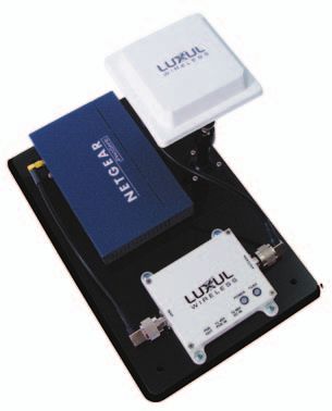
1. Position the mounting board with the four holes for
the signal booster at the bottom of the board and the
three holes for the antenna mount at the right side of
the board.
2. Attach the Shock-WAV Signal Booster and antenna
mount to the pre-drilled holes in the mounting board
using the screws provided.
ANTENNA
3. Attach the antenna to the mounting bracket by
INPUT
turning it in a clockwise motion until it stops. Don’t POE POE
OUT IN
48V
DC IN
over tighten. The adjustable antenna mount will allow
setting the antenna angle. FIGURE 1
4. Mount the AP to the mounting board using the
included Velcro mounting strips.
Connecting the Coax Cables
1. Connect the X-WAV antenna to the Shock-WAV Wi-Fi
Signal Booster using the N-Male to N-Male cable. Be
sure to connect the cable to the side of the Shock-
WAV Wi-Fi Signal Booster labeled “Antenna”.
2. Remove the stock antenna from your AP. Set aside the
stock antenna, you will not need it for this installation.
3. Using the included N-Male to RP-SMA cable connect the
Shock-WAV Wi-Fi Signal Booster to the antenna port of
ANTENNA
INPUT
your AP. Be sure to connect the cable to the side of the POE POE 48V
OUT IN DC IN
Shock-WAV Wi-Fi Signal Booster labeled “INPUT”.
FIGURE 2
Powering Options
For maximum flexibility you may power the Pro-WAV Board Mounted Range Extender Kit by
Direct Power or POE using the optional Luxul Wireless POE Injector or a POE injector that
supports legacy mode. The Luxul Wireless Signal Booster does not support 802.3af POE
power. (Check POE’s documentation).QUICK Install GUIDE
Direct Power: (Figure 3)
NOTE: If powering the Shock-WAV
Signal Booster directly the
“POE OUT” port is disabled.
1. Connect the Ethernet cable from your data/
network source to the “10/100M” port of your
Netgear AP, (See AP’s documentation).
2. Attach the Luxul power supply (48VDC) to the
ANTENNA
INPUT
“48V DC IN” port of the Signal Booster. POE POE 48V
OUT IN DC IN Data
3. Connect Netgear power supply to the AP’s power Source
port (See AP’s documentation). Power Power Ethernet
4. Plug the power supplies into your power source. Supply Supply Power
Coax
FIGURE 3
Optional POE (Power Over Ethernet) (Figure 4)
1. Connect the Ethernet cable from your data/network
source to the “48V POE IN” port of the Wi-Fi Signal
Booster.
2. Connect the next Ethernet cable from the “POE OUT”
of the Wi-Fi Signal Booster to the “10/100M” port of
your Netgear AP, (See AP’s documentation).
3. Be sure all cables are connected securely and power
up your POE injector.
ANTENNA
INPUT
4. You may now power your POE injector. POE POE 48V
OUT IN DC IN Data
Source
Optional POE with the POE-1Port Injector (Figure 5)
Ethernet
Power
Coax
Install the optional POE injector where you have FIGURE 4
access to your data/network source Ethernet cable and
Data/Pwr
power sources. Out
(Ethernet)
Power
In POE-
NOTE: The POE-1Port is a non 802.3af/at 1port
Injector
compliant injector
Data
Power Data In
Source Source (Ethernet)
FIGURE 5Deployment
The Pro-WAV PWK1 Wi-Fi Range Extender Kit is designed to placed in an attic, above
ceiling tiles, or utility closet. For best results, the Kit should be deployed where the
maximum amount of signal can be sent throughout the desired coverage area. The flat
panel antenna included in the Wi-Fi Range Extender Kit is a directional antenna and should
be pointed toward the desired coverage area, similar to aiming a flash light. Use the
adjustable antenna mount included in the kit to aim your antenna.
Placement Within Your Coverage Area
Luxul Wireless products, particularly those implementing our patented booster products,
are often capable of emitting enough signal strength to cover an entire home regardless
of orientation. However, for best results, the deployment suggestions, figure 6,
are recommended.
FIGURE 6QUICK Install GUIDE
Large or Unusually Shaped Coverage Areas
If installing the Wi-Fi Range Extender Kit in the center of the desired coverage area or you
have a large or unusually shaped coverage area you may want to consider adding a second
antenna with the optional X-WAV XWK-24-FP7A Antenna Kit. Figure 7 demonstrates how
two antennas can more effectively cover large or unusual coverage areas.
FIGURE 7Troubleshooting
Weak or non-existent coverage.
• Make sure the cables are properly connected and that there is power to the Shock-WAV
Wi-Fi Signal Booster and your WAP (Wireless Access Point).
• If the Signal Booster is powered the Power and TX/RX indicators will be solid green. If
data is passing through the signal booster the TX/RX indicator will be Green with flashing
Red. If there is no indication of data pass through remove the Luxul unit and test with
the WAPs stock antennas to make sure the WAP’s radio is transmitting. If the WAP is not
transmitting check your WAP’s documentation for possible causes.
• Sometimes, WAP’s with multiple antennas have primary and secondary antenna ports.
Be sure to connect the signal booster to the primary antenna port of the WAP as many
secondary ports are receive only, or do not transmit at the same power level as the
primary antenna port. If your WAP has more than one antenna port, try connecting
to a different port and/or, if available, change the administration settings disable the
secondary antenna port. (See your WAP’s documentation).
• Ensure the X-WAV antenna is properly positioned. Directional antennas should face the
direction of the area to be covered. Omni antennas should be centered in the desired
coverage area. Antennas should have minimum of 2 feet (.6 meters) of clearance with
no obstructions.
• The Luxul Wireless Circular Polarized signal is superior for penetrating wood, concrete,
and stucco, but all wireless signals can be disrupted by certain obstructions, including
large metal objects, or strong magnetic fields. Try orienting the antenna where line-of-
sight access to the desired coverage area is available.
After checking the above items, if your Luxul Wireless product still does not seem to be
functioning properly, please contact Technical Support at: support@luxulwireless.com
For warranty information please go to: www.luxulwireless.com/warranty/
Results may vary depending on building layout, type of construction and other environmental factors
including Wi-Fi traffic, Microwave Ovens, Cordless Phones etc.
FCC NOTICE: The use of all radio equipment is subject to regulations in each country. To comply with FCC part
15 rules in the United States, radio equipment must only be used in systems that have been FCC certified. It is the
responsibility of the user/professional installer/operator to ensure that only approved equipment/systems are
deployed. To ensure FCC part 15 compliance, Luxul amplifier products should only be installed in certified systems
by licensed professionals.
FCC Certification Support for OEMs: Luxul Wireless offers FCC certification assistance and engineering support
for qualified OEM’s interested in certifying complete amplified WLAN systems. Please contact us for details.
LUXUL WIRELESS | 357 South 670 West, Lindon, UT, 84042
p: 801-822-5450 f: 801-822-5460 | www.luxulwireless.com
© 2010 Luxul Corp. All rights reserved. LUX-QIG-090320101236-PWK1FC2You can also read