Differential pressure gauge with output signal For the process industry, high overload safety up to 400 bar Models DPGT43HP.100 and DPGT43HP.160 ...
←
→
Page content transcription
If your browser does not render page correctly, please read the page content below
Pressure
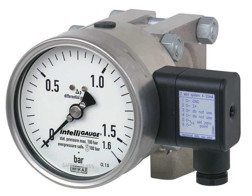
Differential pressure gauge with output signal
For the process industry, high overload safety up to 400 bar
Models DPGT43HP.100 and DPGT43HP.160
WIKA data sheet PV 17.13
for further approvals see
page 4
Applications
■■ Acquisition and display of process values
■■ Output signals 4 ... 20 mA, 0 ... 20 mA, 0 ... 10 V for the
transmission of process values to the control room
■■ For measuring locations with a high differential pressure
overload and/or high working pressures (static pressures),
also in aggressive environments
■■ Easy-to-read, analogue on-site display needing no exter-
nal power
Special features
■■ High working pressure (static pressure) and high overload
safety, selectable up to 40, 100, 250 or 400 bar
Differential pressure gauge, model DPGT43HP.100
■■ Hydraulic cushioning protection against rapid pressure
changes
■■ No configuration necessary due to “plug-and-play”
■■ Differential pressure measuring ranges from 0 … 60 mbar
■■ Individual, non-linear characteristic curves (e. g. x2 or √x
for flow measurement)
Description
Wherever the differential pressure must be indicated locally from wear and friction. From this, the electrical output signal,
and, at the same time, a signal transmission to the central proportional to the pressure, of 4 ... 20 mA, is produced. In
control or remote centre is desired, the model DPGT43 addition, the electrical zero point can be set manually.
intelliGAUGE® (US patent: 8,030,990) can be used. The
electronic WIKA sensor, integrated into the model 732.14 These differential pressure measuring instruments are made
high-quality, mechanical differential pressure gauge, of highly corrosion-resistant stainless steel. A high overload
combines the advantages of electrical signal transmission safety is achieved by the all-metal construction and the
with the advantages of a local mechanical display. close-fitting design of the diaphragm pressure element.
Even if the voltage supply is completely lost, the differen- The use of high-quality stainless steel materials and the
tial pressure can be read securely. The robust diaphragm robust design are geared to applications in the chemical
measuring system produces a pointer rotation proportional and process engineering industries. Thus the instrument is
to the pressure. suitable for liquid and gaseous media, also in aggressive
An electronic angle encoder, proven in safety-critical automo- environments.
tive applications, determines the position of the pointer shaft
– it is a non-contact sensor and therefore completely free
WIKA data sheet PV 17.13 ∙ 08/2018 Page 1 of 5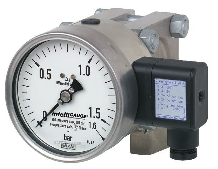
Specifications
Mechanical data
Mechanical version                         Highest overload safety either side, pressure ratings PN 40, 100, 250 or 400, system fill fluid of
                                           the measuring cell acts as the damping for the display
Nominal size in mm                         100, 160
Accuracy (mechanical display)              ≤ 1.6 % of measuring span (class 1.6 per EN 837-3)
Scale ranges                               0 ... 60 mbar to 0 ... 250 mbar (measuring cell DN 140, for dimensions see page 5)
                                           0 ... 400 mbar to 0 ... 40 bar (measuring cell DN 80)
                                           or all other equivalent vacuum or combined pressure and vacuum ranges

Operating limits                           Overload resistance per EN 837-3
Pressure limitation
   Steady                                  Full scale value
   Fluctuating                             0.9 x full scale value
                                           Observe the recommendations for the use of mechanical pressure measuring systems in ac-
                                           cordance with EN 837-2
Overpressure safety / max. working         Overload safety either side for the following pressure ratings:
pressure (static pressure)                 ■■ PN 40: 40 bar
                                           ■■ PN 100: 100 bar
                                           ■■ PN 250: 250 bar
                                           ■■ PN 400: 400 bar (only for scale ranges ≥ 0 ... 400 mbar)
Media chamber with process connec-         Stainless steel 316Ti (1.4571)
tion (wetted)                              Lower mount, 2 x G ½ female
System fill fluid for the measuring cell   Silicone oil
Pressure elements (wetted)                 Scale ranges ≤ 0 ... 250 mbar: 316L stainless steel
                                           Scale ranges > 250 mbar: 316L stainless steel/Inconel
Venting of the media chambers              PN 40/100: Standard for scale ranges ≤ 0 ... 160 mbar
(wetted)                                   PN 250/400: Standard for scale ranges ≤ 0 ... 250 mbar
                                           Other scale ranges on request
                                           Material: 316Ti stainless steel (1.4571)
Movement                                   Stainless steel
Dial                                       Aluminium, white, black lettering
Pointer                                    Adjustable pointer, aluminium, black
Case                                       Stainless steel
Window                                     Laminated safety glass
Ring                                       Bayonet ring, stainless steel
Damping options
   For dynam. pressure load                Restrictor in the pressure port
   For vibration                           Liquid filling of the case
Permissible temperature range
   Medium                                  -20... +100 °C
   Ambient                                 -20 ... +60 °C (with window from polycarbonate max. 80 °C)
Temperature effect                         max. ±0.5 %/10 K of full scale value (when the temperature deviates from 20 °C reference
                                           temperature)
Ingress protection per IEC/EN 60529        IP54 (with liquid filling IP65)
Installation                               according to affixed symbols: ⊕ high pressure, ⊖ low pressure
Mounting                                   ■■   Rigid measuring lines
                                           ■■   Mounting holes in measuring flange
                                           ■■   Panel mounting flange (option)
                                           ■■   Instrument mounting bracket for wall or pipe mounting (option)

Options                                                                    ■■ Venting of the media chamber for scale ranges ≥ 0.4 bar
                                                                           ■■ Lateral connection location (right, left)
■■ Sealings (model 910.17, see data sheet AC 09.08)                        ■■ Panel mounting flange
■■ Other process connections via female or male threads                    ■■ Instrument mounting bracket for wall or pipe mounting
■■ Other system fill fluids in the measuring cell, e.g. for use in         ■■ Valve manifolds (models IV3x and IV5x,
   oxygen environments                                                        see data sheet AC 09.23)
■■ Higher max. working pressure (static pressure) and higher               ■■ With switch contacts (data sheet PV 27.13)
   overload safety (see table page 5)
■■ Output signal 0 ... 20 mA, 0 ... 10 V
■■ Customer-specific characteristic curve (also non-linear)

WIKA data sheet PV 17.13 ∙ 08/2018                                                                                                  Page 2 of 5
Electrical data
Power supply UB DC 12 V < UB ≤ 30 V (variant 1)
DC 14 V < UB ≤ 30 V (variant 2)
Influence of power supply ≤ 0.1 % of full scale/10 V
Permissible residual ripple of UB ≤ 10 % ss
Output signal Variant 1: 4 … 20 mA, 2-wire, passive, per NAMUR NE 43
Variant 2: 4 ... 20 mA, per ATEX
Permissible max. load RA RA ≤ (UB - 12 V)/0.02 A with RA in Ω and UB in V, however max. 600 Ω
Effect of load ≤ 0.1 % of full scale
Impedance at voltage output 0.5 Ω
Electrical zero point Through a jumper across terminals 5 and 6 (see operating instructions)
Long-term stability of electronics < 0.3 % of full scale per year
Electr. output signal ≤ 1 % of measuring span
Linear error ≤ 1 % of measuring span (terminal method)
Resolution 0.13 % of full scale (10 bit resolution at 360°)
Refresh rate (measuring rate) 600 ms
Maximum values for the power supply circuit (only for Ex version)
Power supply Ui DC 30 V
Short-circuit current Ii 100 mA
Power Pi 1W
Internal capacitance Ci 12 nF
Internal inductance Li Negligible
Electrical connection Via angular connector, 180° rotatable, wire protection, cable gland M20 x 1.5, incl. strain
relief, connection cable: Outer diameter 7 ... 13 mm, conductor cross-section 0.14 ... 1.5 mm2,
temperature resistance up to 60 °C
Designation of connection Do not use this
terminals, 2-wire terminal
Terminals 3 and 4: For internal use only
UB+/I+ Terminals 5 and 6: Reset zero point
+0 V/GND
Cable connection
Angular connector
from PA6, black, IP65,
max. 1.5 mm2
Cable gland M20 x 1.5
WIKA data sheet PV 17.13 ∙ 08/2018 Page 3 of 5Approvals
Logo Description Country
EU declaration of conformity European Union
■■ EMC directive
■■ Pressure equipment directive
■■ ATEX directive (option)
EAC (option) Eurasian Economic Community
■■EMC directive
■■Pressure equipment directive
■■Low voltage directive
■■Hazardous areas
GOST (option) Russia
Metrology, measurement technology
KazInMetr (option) Kazakhstan
Metrology, measurement technology
- MTSCHS (option) Kazakhstan
Permission for commissioning
BelGIM (option) Belarus
Metrology, measurement technology
UkrSEPRO (option) Ukraine
Metrology, measurement technology
DNOP (MakNII) (option) Ukraine
■■ Hazardous areas
Uzstandard (option) Uzbekistan
Metrology, measurement technology
- CRN Canada
Safety (e.g. electr. safety, overpressure, ...)
Certificates (option)
■■ 2.2 test report per EN 10204 (e.g. state-of-the-art
manufacturing, indication accuracy)
■■ 3.1 inspection certificate per EN 10204 (e.g. indication
accuracy)
Patents, property rights
■■ Current output (2-wire) for pointer measuring instruments
(US 8,030,990, CN101438333)
Approvals and certificates, see website
WIKA data sheet PV 17.13 ∙ 08/2018 Page 4 of 5Dimensions in mm
Standard version
11358441.01
NS Scale range Dimensions in mm Weight in kg
b D1 h ±1 p□ (PN 40/100/250) p□ (PN 400) PN 40/100 PN 250 PN 400
100 ≤ 0 ... 250 mbar 58.5 101 86 140 - 12.1 13.1 -
100 > 0 ... 250 mbar 58.5 101 64 82 86 3.6 3.9 4.5
160 ≤ 0 ... 250 mbar 65.5 161 86 140 - 12.5 13.5 -
160 > 0 ... 250 mbar 65.5 161 64 82 86 4.0 4.3 4.9
Ordering information
Model / Nominal size / Scale range / Process connection / Connection location / Output signal / Scale layout (linear pressure or
square root incrementation) / Max. working pressure (static pressure) / Options
© 05/2008 WIKA Alexander Wiegand SE & Co. KG, all rights reserved.
The specifications given in this document represent the state of engineering at the time of publishing.
We reserve the right to make modifications to the specifications and materials.
08/2018 EN
WIKA data sheet PV 17.13 ∙ 08/2018 Page 5 of 5
WIKA Alexander Wiegand SE & Co. KG
Alexander-Wiegand-Straße 30
63911 Klingenberg/Germany
Tel. +49 9372 132-0
Fax +49 9372 132-406
info@wika.de
www.wika.deYou can also read