Tarot 2-Axis Brushless Gimbal for Gopro User Manual V1.0
←
→
Page content transcription
If your browser does not render page correctly, please read the page content below
Tarot 2-Axis Brushless Gimbal for Gopro User Manual V1.0
1. Introduction
Tarot T-2D gimbal is designed for the Gopro Hero3, which is widely used in film, television
productions, advertising aerial photography, etc. Using 6061T6 aluminum alloy full CNC
precision machining and brushless motor driving, its overall framework is designed with the idea
of compact, easy installation, high precision, lightweight, high stability and many other
characteristics. Even if the aircraft is in high-speed flight, it can still stabilize and control the
Gopro camera precisely with the highest stability, so pictures or videos output can reach the best
quality.
2. Specifications
1. Support GOPRO Hero3 video output.
2. Support reverse power supply protection and power voltage compensation.
3. Support motor connector short circuit protection.
4. Support tilt initial angle setting.
5. Support adjustable gains and 3D attitude display on PC software.
6. Support stick rate mode and position mode.
7. Supported receiver type: conventional/S-BUS/DSM2/DSMJ/DSMX receiver.
8. Supported RC: PPM/PCM/2.4G.
9. Operating supply: DC 7.4V~14.8V (Li-Po 3S is recommended)
10. Operating current: 200mA-500mA (Depending on power supply voltage and motor power)
11. Operating temperature: -15ºC~65ºC.
12. CPU: Double 32bit ARM
13. Sensor technology: 3-axis MEMS gyro and accelerometer.
14. Max angular rate: 2000 º /sec.
15. Max acceleration: 16g.
16. Control frequency:2000Hz
17. Motor driver frequency: 20KHz (quiet and smooth)
18. Control accuracy: 0.1°
19. Control range: -45º~45º(roll), -135 º~90 º(tilt).
20. Attitude arithmetic: BLDC gimbal dedicated brushless motor decoupled EKF algorithm.
21. Aerial photography equipment: GOPRO Hero3.
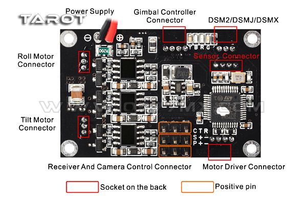
3. Connections
Connections instructions:
WWW.0577MX.COM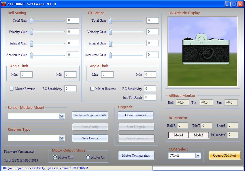
1.Power supply:
   DC 7.4V~14.8V (Li-Po 3S is Recommended)
2.Gimbal controller connector:
   Via USB module connected to the computer, used to adjust the gimbal controller parameter and
status monitoring.
3.Motor driver connector:
   Via USB module connected to the computer, used to adjust the motor driver module( motor
poles and power), and voltage and current monitoring.
4.Receiver and camera control connector:
   R: conventional receiver roll channel input
   T: conventional receiver tilt channel input
   C: conventional receiver stick mode channel input (rate mode and position mode)
   S: S-BUS receiver or conventional receiver camera input
   P: camera control servo output (Infrared camera module can be connected)
   +: 5V output
   -: power ground
5.DSM2/DSMJ/DSMX:
   Used to connect DSM2/DSMJ/DSMX receiver
6.Roll and tilt motor connector:
   Used to connect motor
7.Sensor connector:
   Used to connect sensor module

4. Video line:

                                  WWW.0577MX.COM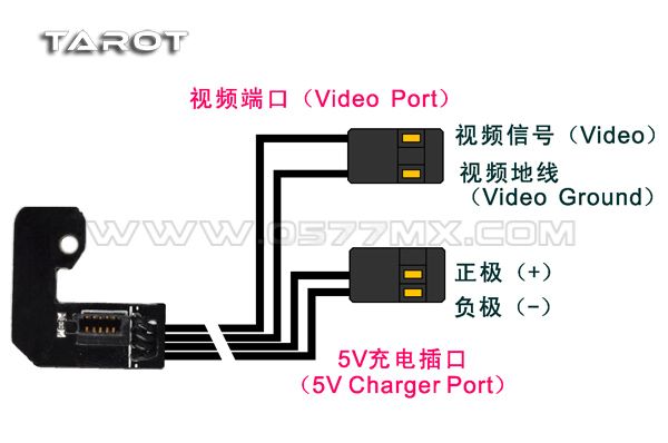
5. LED indication
Y: Yellow,B: Blue,R: Red,G: Green
Yellow blink 2 times           Initialization successfully
Yellow solid                   Initialization not finished, keep gimbal static
Blue blink                     Receiver connected or PC software connected(normal)
Blue LED solid                 Receiver not connected(normal)
Red solid                      Angle out of band or error occur
Green solid                    Over current,After troubleshooting, reapply power can recover

6. Protection function
Reverse power protection:
      When the power is reversed, the gimbal won’t response avoiding burning the control panel,
thereby enhancing reliability.
Motor output short circuit protection function:
      When the motor output is shorted motor output PTZ control panel will turn off and the green
light is lit, thereby protecting the control panel from burning. After the short troubleshooting, you
must re-power to lift the protection.
Angle overrun protection function:
      When the camera angle exceeds the limit, it will automatically shut down the motor output
and the red light is lit, thereby protecting the lines laid down being wrapped broken in unexpected
situations. After the short troubleshooting, re-power or re-start the motor on the computer side,
then the gimbal can be restored.

7. Setup instruction
     Brushless gimbal system uses a dual-processor solution (gimbal controller processor and

                                    WWW.0577MX.COM
motor driver processor). Software interface is as follows.
A、Gimbal controller software UI instructions
Connect USB programmer to gimbal controller port. Open ZYX-BMGC.exe, run
ZYX-BMGC software, software interface is as follows.
(1) Open port:
Select COM port in the software, and click “Open COM Port”. After that, you can power on
gimbal. The power supply should make gimbal work safely.
(2) Gimbal controller connection status:
After the initialization process, the status bar should show “All parameters updated!”. This
means gimbal has been connected to software successfully. Toggle arbitrary axis of the gimbal,
you should see the movement of the gimbal in 3D attitude display on the screen. For safe
configurations, when gimbal connected, the program automatically sets motor output mode off.
(3) Sensor module mount:
You should select right sensor module mounting way at “Sensor Module Mount” according
to step1. Then, you should observe “3D Attitude Display” whether can reflect camera’s real
WWW.0577MX.COMmotion.
(4) Receiver type:
Connect your receiver’s connection to ZYX-GS’ receiver input port, and select right receiver
type in configuration program. When the receiver type changed, you should click “Write Settings
to Flash”, and restart ZYX-GS.
DSM2/DSMJ/DSMX receiver type:
DSM2-1:Transmitter is DX7 etc. (binding by 6 or 7 channels receiver)
DSM2-2:Transmitter is DX8, DSX9 etc. (binding by 6 or 7 channels receiver)
DSM2-3:Transmitter is DX8, DSX9 etc. (binding by 9 channels receiver)
DSM2-4:Transmitter is DM8, DM9 module. (binding by 6 or 7 channels receiver)
DSMJ: Transmitter is DSMJ format. (Binding by matched receiver)
DSMX-1:Transmitter is DX 8 etc. (11ms mode, binding by matched receiver)
DSMX-2:Transmitter is DX 8 etc. (22ms mode, binding by matched receiver)
(5) RC monitor:
After you select receiver type and restart gimbal, the window will give you a real time
display for all input channels.
R: roll input channel.
T: tilt input channel
S: camera remote infrared shutter control channel
C: RC Mode Switch:
Mode1: stick rate mode
Mode2: stick position mode
(6) Angle limits:
You can limit the roll angle and tilt angle for your need. Roll angle limits range is -45º~45º,
tilt angle limits range is -135º~90º.
NOTICE: when the attitude of the gimbal is not in limits range, gimbal will set motor output
mode off for safety. When you configure gimbal at first time, you should set angle limits with
lower values.
(7) Motor direction:
Motor direction is selected according to the motor rotation.
(8) Initial tilt angle:
In stick rate mode, when the gimbal power on, the initial tilt angle is determined by this
parameter.
(9) Motor output mode:
Motor output mode is used for keeping the gimbal safe when configure gimbal.
Motor off mode: gimbal shuts down motor output signal.
Motor on mode: gimbal outputs motor signal, at this time, the gimbal stabilization works.
NOTICE:
(a) When the motor output mode is “motor off”, you can set sensor module mounting way.
(b) When the motor output mode is “motor on”, there are two situations gimbal will automatically
shut down motor output signal. First situation: the total gain is zero or other three gains are zero
on any axis. Second situation: current attitude of the gimbal is not in angle limit ranges. When you
need motor output, you should set gains value non-zero, keep the gimbal level and make sure the
sensor module mounted rightly.
WWW.0577MX.COM(10) PID parameters adjustment:
PID parameters range is [0-500], the basic rule is the total sensitivity can not be 0, speed
sensitivity and integration sensitivity can not both be 0. If break these rules the gimbal will turn
off the motor, this can protect gimbal and camera.
Under the same load condition, if motor power parameter is increased, you should reduce the
gimbal gains. If its value is decreased, you should increase the gimbal gains. In guarantee the
motor power under the condition of enough, you should minimize power value for larger gains to
get better gimbal stabilization performance. Notice that reducing motor power will affect the
ability of the gimbal resisting disturbance.
Step 1. Accelerate gain:
First, set the total gain to an appropriate value (e.g. 100), set the velocity gain and integral
gain to the minimum value(e.g. 1).Secondly, increase accelerate gain gradually until the gimbal
shaking. This value is the largest accelerate gain. Finally, reduce the accelerate gain by 20% as the
final gain.
Step 2. Velocity gain:
First, increase velocity gain gradually until the gimbal shaking. This value is the largest
velocity gain. Finally, reduce the velocity gain by 20% as the final gain.
Step 3. Integral gain:
First, increase integral gain gradually until the gimbal shaking. This value is the largest
integral gain. Finally, reduce the integral gain by 20% as the final gain.
Step 4. Fine-tune gains:
After completing the above steps, we can be appropriate to fine-tune each gains and get better
result.
(11) Write settings to flash:
After your configuration finished, click ”Write Settings To Flash”. When you write flash
successfully, the settings are saved in gimbal. Next time, when you restart gimbal, these settings
are loaded automatically.
B. Gimbal motor driver software UI instructions
Connect USB programmer to motor driver port. Open ZYX-BMGC.exe; run ZYX-BMGC
software, click ‘motor configuration’, the interface of motor configuration is in the following
figure.
WWW.0577MX.COM(1)Open COM port:
Select COM port in the motor configuration, and click ‘Open COM Port’. After that, you can
power on the gimbal. The power supply should make the gimbal work safely.
(2)Motor driver module connection status:
After motor driver module initialization process, the status bar should show “All parameters
updated!”. This means motor driver module has been connected to software successfully.
(3)Polar num:
Polar num is motor magnetic pole number; this parameter will affect the reduction ratio and
highest speed of the motor. Usually, its value should be set to the actual number of the motor. If
you need special performance, its value can be set to different from the actual pole number of the
motor.
(4)Motor power:
The range of motor power is 0%-100%, its value can be adjust according to load. Under the
same load condition, if motor power parameter is increased, you should reduce the gimbal gains.
If its value is decreased, you should increase the gimbal gains. In guarantee the motor power under
the condition of enough, you should minimize power value for larger gains to get better gimbal
stabilization performance. Notice that reducing motor power will affect the ability of the gimbal
resisting disturbance.
(5)Signal monitor:
Display supply voltage and operating current of the gimbal. Voltage value displayed will be
smaller than the power supply voltage of 0.3V or so.
(6)Write settings to flash:
After your motor configuration finished, click”Write Settings to Flash”. When you write flash
successfully, the settings are saved in gimbal. Next time, when you restart it, these settings are
loaded automatically.
8. Upgrade firmware
WWW.0577MX.COMNotice: Because this gimbal controller adopts double CPU solution, as main controller CPU
and motor driving CPU, there are different upgrade firmware files for these CPUs. Before
upgrading firmware, you should make sure the hardware interface connected rightly and choosing
corresponding firmware files.
1. Main controller firmware upgrade:
Firstly, you should connect USB programmer to main controller port, and select right COM
port, click “Open Firmware”, choose the firmware file you want to upgrade(do not click” Open
COM Port”). After that, click “Start Upgrade”, and then, power on the gimbal. When the progress
bar finished, firmware upgrades successfully. After firmware upgrades finished, you can open
COM port to connect gimbal to configuration program. The new main controller firmware version
can be seen in the window.
2. Motor driver firmware upgrade:
Firstly, you should connect USB programmer to motor driver port, and click ‘motor
configuration’ to enter into the interface of motor configuration. Select right COM port, click
“Open Firmware”, chooses the firmware file you want to upgrade (do not click” Open COM
Port”). After that, click “Start Upgrade”, and then, power on the gimbal. When the progress bar
finished, firmware upgrades successfully. After firmware upgrade finished, you can open COM
port to connect gimbal to configuration program. The new motor driver firmware version can be
seen in the window.
WWW.0577MX.COMYou can also read