Deployable Antenna System Electrical Model - DATASHEET Innovative, deployable upon command Antenna System Electrical Model - Innovative ...
←
→
Page content transcription
If your browser does not render page correctly, please read the page content below
Deployable Antenna System
Electrical Model

DATASHEET
ISIS-ANTS_ELEC-DSH-0001, version 3.0

Innovative, deployable upon command Antenna System Electrical Model

                  ISISPACE Group | Motorenweg 23, 2623CR, Delft, The Netherlands | www.isispace.nl
Doc ID: ISIS-ANTS_ELEC-DSH-0001
Issue: 3.0
DATASHEET Date: 2020-12-23
Page: 2 of 7
Applications
CubeSat TT&C
CubeSat AIV
General description
The ISIS deployable antenna system (AntS) provides a configurable antenna deployment system with a
configurable user interface. The AntS can house up to four antenna elements which may be tuned for typical
VHF and UHF frequencies in use by nano satellites as requested by the end user. The antennas may be
configured for various RF antenna configurations (4 x monopole, 2 x dipole or 1 x turnstile) and are deployed
under user command by a redundant control mechanism.
Especially for early software development and mission AIV it was proven convenient to have a version of the
AntS without any RF functionality and where the burn mechanism does not perform non reversible burning or
burn wires but is simply indicated by indicator LED’s. This requirement led to the definition of the AntS-
electrical model (ANTS-ELEC) which is described further in this document.
Optional features
• Supply Voltage 5V available on demand
• ADCS sensor set (sun sensor/temps sensor)
Compatibility
• Compatible with ISIS products and recent Pumpkin and GomSpace products.
• Compliant to CubeSat standard.
Quality assurance
• Units acceptance tested for workmanship.
Product features
• Power Consumption:
o Nominal < 40mW
o During Deployment 2W
• Supply Voltage 3V3 with a specified range of 3 to 3.6V
• Deployment simulation easily performed by means of switches.
• Deployment confirmation switch per antenna
• I2C Interface
• Software safe/arm implementation
• Dual redundant deployment system
• Deployment Duration: < 3 s above 15°C
• Operational Temperature Range: -20 to 60 °C
• Miniature 9pin or 8pin OMNETICS© connector for power and data interfaces.
Ordering information
Please contact sales@isispace.nl for ordering information
© 2021. All rights reserved. Disclosure to third parties of this document or any part thereof, or the use of any information contained therein
for purposes other than provided for by this document, is not permitted except with express written permission of ISISPACE Group.
PUBLICDoc ID: ISIS-ANTS_ELEC-DSH-0001
Issue: 3.0
DATASHEET Date: 2020-12-23
Page: 3 of 7
Block Diagram
A
Temperature
Antenna 1 Antenna 2
Sensor
Release Release
circuit circuit
J4 Debug / ICD2
Antenna 3 Antenna 4
Release Release
Arm circuit
Microcontroller circuit
I2C
Vcc
Repeater
Vcc
I2CA
J1 (Single I2C
I2CB bus option)
Antenna Antenna
1 switch 2 switch
Antenna Antenna
3 switch 4 switch
B
Temperature
Antenna 1 Antenna 2
Sensor
Release Release
circuit circuit
J4 Debug / ICD2
Antenna 3 Antenna 4
Release Release
Arm
Microcontroller circuit circuit
I2C
Repeater
Figure 1 ANTS-ELEC General block diagram
Specification
Table 1 ANTS-ELEC Specification
Parameter Typical Value Comments
Environmental Characteristics
Qualified operational temperature range -20 to +60°C
Storage temperature range -50 to +85°C (RHDoc ID: ISIS-ANTS_ELEC-DSH-0001
Issue: 3.0
DATASHEET Date: 2020-12-23
Page: 4 of 7
Parameter Typical Value Comments
Physical Characteristics
Dimensions (Main) 98 x 98 mm
Overall height 20 to 30 mm
Weight 30 to 40 grams
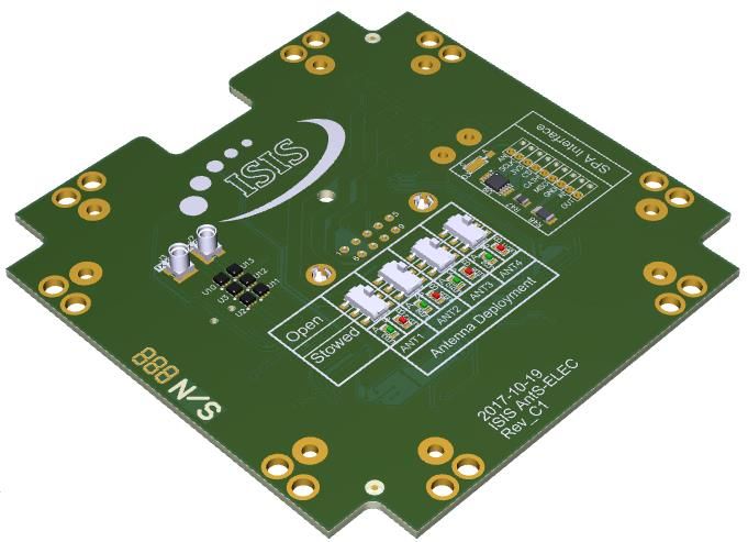
Functional Description
The main functionality of the antenna system is to deploy the stowed antennas so that the antennas can be
used for RF transmissions. In the ANTS-ELEC the activation of burn wires and physical deployment of antennas
has been replaced by status LED's. Green LED indicators are used for the A-side microcontroller and red LED
indicators are used for the B-side microcontroller.
A few of the concepts the system uses will be explained below.
Arming and disarming
In order to prevent the antennas from accidentally deploying, the system has an armed and disarmed state.
The deployment systems for the antennas can only be activated when the system has been armed. The antenna
system can be armed using an I2C command.
Antenna deployment switches
The deployment system of each antenna is equipped with a switch. The function of this switch is to detect
whether the antenna is deployed or undeployed (also referred to as stowed). The switches are connected to
both microcontrollers in the antenna system, which allows their status to be read out using I 2C. In the ANTS-
ELEC the conformation switches are replaced by four deployment simulation switches. The switches have a
“Stowed” state that will indicate an “undeployed” condition to the microcontroller and a “Open” state that will
indicate a “deployed” status to the microcontroller.
Activation safety time limit
In order to prevent the deployment systems from being active too long a safety time limit has been built into
the system. The safety limit is also in place to prevent the deployment systems from draining the satellite’s
batteries when accidentally activated for too long.
Activation tracking
For each deployment system the following information is stored in the microcontroller:
• How many times has the deployment system of the antenna been activated.
• How long in total has the deployment system been active. This is added up over multiple activations.
This information is available from the microcontroller upon request and can be used to determine how long it
took for antenna to deploy. Please note that this information is lost whenever the microcontroller experiences
a reset.
Power Conditioning and Distribution
The Ants is powered by a 3.3V or 5V supply line from the satellite EPS. During the brief period of antenna
deployment the ANTS-ELEC requires approximately 2W of electrical power.
There are two redundant power connections on 9pin or 8pin connector.
© 2021. All rights reserved. Disclosure to third parties of this document or any part thereof, or the use of any information contained therein
for purposes other than provided for by this document, is not permitted except with express written permission of ISISPACE Group.
PUBLICDoc ID: ISIS-ANTS_ELEC-DSH-0001
Issue: 3.0
DATASHEET Date: 2020-12-23
Page: 5 of 7
Electrical Description
The ANTS-ELEC electrical architecture is described in Figure 2. The whole deployment system is composed of
two fully redundant microcontroller based systems. Antennas deployment is indicated by burning LED
indicators as described above. Antenna status (stowed or deployed) is measured using headers and short
circuit jumpers. One I2C repeater is used for each data bus in order to provide better isolation and robustness
of the I2C bus. Two temperature sensors are present on the board.
A
Temperature
Antenna 1 Antenna 2
Sensor
Release Release
circuit circuit
J4 Debug / ICD2
Antenna 3 Antenna 4
Release Release
Arm circuit
Microcontroller circuit
I2C
Vcc
Repeater
Vcc
I2CA
J1 (Single I2C
I2CB bus option)
Antenna Antenna
1 switch 2 switch
Antenna Antenna
3 switch 4 switch
B
Temperature
Antenna 1 Antenna 2
Sensor
Release Release
circuit circuit
J4 Debug / ICD2
Antenna 3 Antenna 4
Release Release
Arm
Microcontroller circuit circuit
I2C
Repeater
Figure 2 Ants-EM Electrical block diagram (no RF)
Detailed interface information and CAD models of the entire ANTS-ELEC may be delivered on request.
RF Description
No RF Functionality is present on the board.
Grounding Scheme
There are three redundant ground connections on 9pin connector with common system ground used.
Detailed interface information and CAD models of the entire ANTS-ELEC may be delivered on request.
© 2021. All rights reserved. Disclosure to third parties of this document or any part thereof, or the use of any information contained therein
for purposes other than provided for by this document, is not permitted except with express written permission of ISISPACE Group.
PUBLICDoc ID: ISIS-ANTS_ELEC-DSH-0001
Issue: 3.0
DATASHEET Date: 2020-12-23
Page: 6 of 7
Mechanical Description
The ISIS ANTS-ELEC is designed to be mounted onto the ISIS CubeSat structure with four M2.5x10 CSK Torx
screws. The mounting holes for mounting the structures top/bottom panel are used for mounting the ANTS-
ELEC module or alternatively it may be used as a loose PCB laying on a table.
Detailed interface information and CAD models of the entire ANTS-ELEC may be delivered on request.
Software
The ANTS-ELEC may be controlled by the satellite command computer sending commands to one or both of
the redundant microcontrollers. An illustrative commands set is provided below:
• Activate/deactivate the burn mode of the ANTS-ELEC
• Activate individual burn resistors or an automatic burn sequence deploying all four antennas in
sequence.
• Put the ANTS-ELEC processor in sleep mode to limit power consumption.
Status telemetry may be retrieved from the ANTS-ELEC by requesting it from one or both of the redundant
microcontrollers. An illustrative telemetry list is provided below:
• Retrieve the current version of the microcontroller firmware
• Retrieve the on-board temperature
• Retrieve the deployment status of each of the four antennas.
• Retrieve the total burn time (stored in non-volatile memory) of each of the four antenna deployment
resistors.
• Retrieve the total number of confirmed deployments (stored in non-volatile memory) of each of the
four antenna deployment resistors.
Functions/Commands
The ISIS Antenna System Electrical Model contains the following functionality:
• Reporting antenna deployment status
• Arming and disarming the antenna system
• Automated sequential antenna deployment
• Storage and reporting of activation count and total activation time
• Reporting system temperature
Please note that all the commands are available on both the A and B microcontroller. Since these are completely
separate and independent, commands sent to the A side microcontroller will not affect the B side
microcontroller. For example, arming the antenna system through the A side microcontroller will only allow
the A side microcontroller to deploy the antennas.
Commands can have responses (return values). These responses need to be retrieved from the controller using
a separate data transfer (master read) following the data transfer that contained the command (master write).
The response of a command will be generated at the time of reception of the command and not at the time
the response is retrieved from the transceiver. This applies for example to the commands of the antenna system
to measure the telemetry values: the measurements are performed when the command is received by the
antenna system. The response to a command will be available until another command that has a response is
executed.
Detailed interface information and CAD models of the entire ANTS-ELEC may be delivered on request.
© 2021. All rights reserved. Disclosure to third parties of this document or any part thereof, or the use of any information contained therein
for purposes other than provided for by this document, is not permitted except with express written permission of ISISPACE Group.
PUBLICDoc ID: ISIS-ANTS_ELEC-DSH-0001
Issue: 3.0
DATASHEET Date: 2020-12-23
Page: 7 of 7
Disclaimer
The contents of this document are subject to the relevant provisions in the contract concluded between the
parties. ISISPACE Group (“ISIS”) shall not be liable, in full or in part, for any damage arising out from the
application or use of any product or circuit described herein, in case such application or use are carried out in
a manner not in line with the instructions and warranties provided in the User Manual, Safety Manual, product
information sheets or any other document provided by ISIS upon the delivery of the product (“Documents”).
Further, ISIS shall not be liable for any damage caused by any use which exceeds the function(s) of the product,
or does not conform to such function(s) as described in the Documents. ISIS shall not be liable for any damage
arising from a use which is not carried out in a manner conforming to acceptable practices in the aerospace
industry.
ISIS warrants that the product is supplied after relevant tests had shown the product is in good order and
functioning, as far as these tests may indicate and predict product functionality.
© 2021. All rights reserved. Disclosure to third parties of this document or any part thereof, or the use of any information contained therein
for purposes other than provided for by this document, is not permitted except with express written permission of ISISPACE Group.
PUBLICYou can also read