CADvent Plug-In for AutoCAD
←
→
Page content transcription
If your browser does not render page correctly, please read the page content below
CADvent Plug-In for AutoCAD

           for version 1.8 AutoCAD only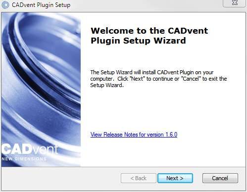
lindab | we simplify construction

Table of Content
Manual for Lindab CADvent Plug-in for AutoCAD .................................................................. 3
  General Information ........................................................................................................... 3
  Installation and activation ................................................................................................... 3
     Installation requirements ................................................................................................ 3
     Installation process......................................................................................................... 4
  List of functions and User Interface .................................................................................... 7
     Graphical User Interface for CADvent Plug-In ................................................................ 7
     The Graphical User Interface for CADvent Plug-In without MagiCAD ............................. 7
     List of functions ......................................................... Fehler! Textmarke nicht definiert.
  Add Space ......................................................................................................................... 8
  lindQST Upload ................................................................................................................11

2/22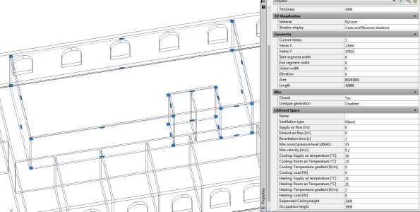
lindab | we simplify construction

Manual for Lindab CADvent Plug-in for AutoCAD

General Information
The Lindab CADvent Plug-In is developed to support CADvent advanced production
orientated features on top of MagiCAD using the production orientated objects in
MagiCAD.
Additional to this, the Plug-In offers features that are also available on computers
without MagiCAD.
Please read more about this in ‘List of functions and User Interface’

Installation and activation
The latest version of the CADvent Plug-in can be downloaded from
http://itsolution.lindab.com/downloads/cadventplugin/cadventplugin.exe

Installation requirements
The CADvent plugin supports AutoCAD 2010 to 2015 on 32 or 64 bit computer.

For the extended version the plug in requires MagiCAD 2013.11 which runs on
AutoCAD 2010 to AutoCAD 2014 or MagiCAD 2014.4 for AutoCAD 2010 to 2015 on
32 or 64 bit computers. The plugin supports Windows 7 and Windows 8.
NOTE: You need to have local administrator rights to install the Plug-in on your
computer.

3/22
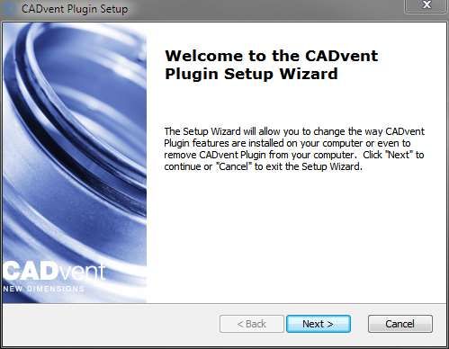
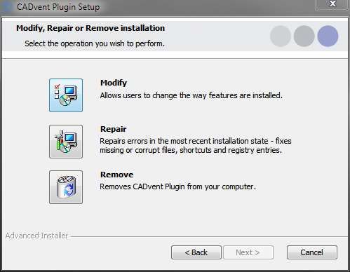
lindab | we simplify construction

Installation process

Download the installation file and save it on your computer for later installation or
install it by pushing the “Run” button. If you have an earlier version of CADvent
Plug-In installed the installation process first likes to uninstall the current version of
the Plug-In.

  Press Next and in the following Window Remove to uninstall the current version.

4/22
lindab | we simplify construction

Now you can install the software. Please activate the installation file again. The
newest features can be listed up with the link you can find in the middle of the
popup window.

5/22
lindab | we simplify construction

The next dialog ask you to select a market area. The selection includes certain
translations and local settings for the production such as standard duct lengths and
flange types:

At the end of the installation process you will be asked to register the software.
Enter your contact details and press “Activate”, the green tick confirms the
activation. Then close the dialog by pressing the “Close” button.

NOTE: You need to be online for the registration process.

                                       Max Mustermann

                                       MaxMustermann@Lindab.com

Now the installation is completed and you can launch MagiCAD including the
CADvent Plug-in.

6/22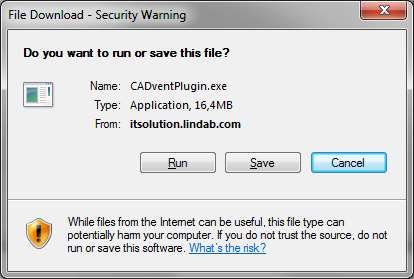
lindab | we simplify construction

List of functions and User Interface
Graphical User Interface for CADvent Plug-In

The Graphical User Interface for CADvent Plug-In without MagiCAD
The CADvent Plug-In on computers without MagiCAD contains a Ribbon palette to
access the commands.

List of functions
              Create a 3D space object to add room information for uploading to
              lindQST, to calculate air devices or water products optimized for the
              specific room requirements

                    Upload the 3D spaces to lindQST
          InCapsa
 Space

                    Draw an InCapsa wall panel system. The cost effective system that
                    makes it easier to mount and cover ventilation systems in buildings

                    Draw an InCapsa fee hanging panel system.

                    Generates reports for all ventilation products.
 Common

                    In the About button you can find information about market settings,
                    contact information and CADvent plugin version number.

7/22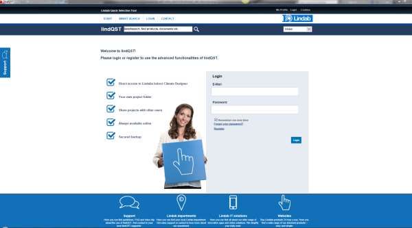
lindab | we simplify construction
Add Space
The 3D Space element gives the user the possibility to create 3D objects in the
drawing to create zones. The zones can be created as simple rectangular boxes
(default) or as Polylines (Type P in the command Line, or activate Polyline on the
right click menu) to create zones which follow the architecture.
The Space object allows the user to divide the drawing into several rooms or zones
which can be uploaded to LindQST, the Lindab Quick Selection Tool, for selecting
and calculating water and air products.
Rectangular rooms:
Activate the Add Space command.
Click on one edge of the room
Click on the opposite edge of the room
Define a rectangular space object
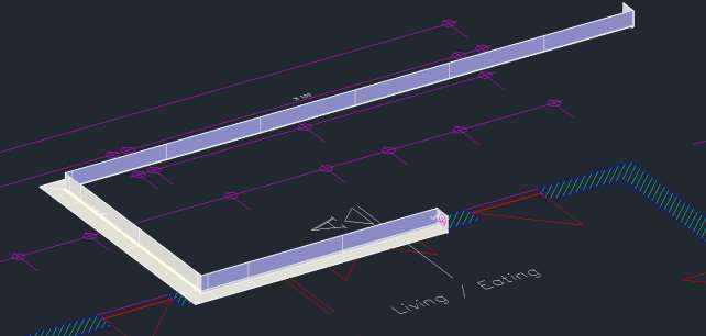
Non rectangular room:
Activate the Add Space command.
Type P in the command line to activate the polyline command
Click on one edge of the room
Follow the walls of the room, by clicking on each edge
Stop at the last edge and type D (done) to close the Polyline
8/22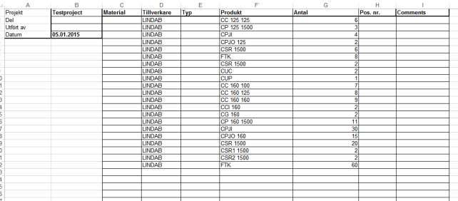
lindab | we simplify construction

              Define a non-rectangular space object

When you have created a zone you can change the parameter in the AutoCAD
Properties to define the requirements for the room.

CADvent Space in drawing with AutoCAD properties

Thickness:                               Height of the space object
Name:                                    Name of the Room/ Zone (required)
Ventilation Type:                        Mixed, Displacement or Chilled Beams
Supply and Exhaust air flow in l/s:      Total air volume for this room/space

9/22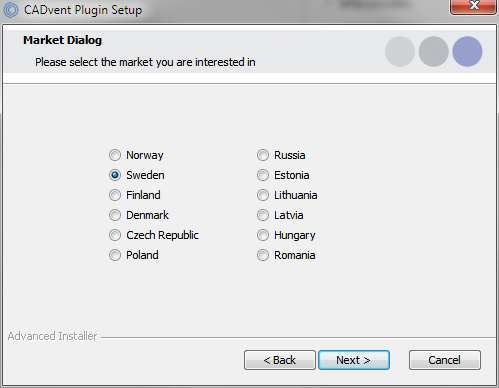
lindab | we simplify construction

Reverberation time in s:              Sound reverberation time
Max. sound pressure level in dB(A): Max allowed sound level in the occupied zone
Max. velocity in m/s:                 Allowed average air velocity in the occupied
                                      zone
Occupation distance:                  Max. distance from displacement unit where
                                      the air velocity is allowed to prevail
Cool./Heat. Supply air temp. in °C:   Temperature of the supply air
Cool./Heat. Room air temp. in °C:     Temperature of the room air
Cool./Heat. Load in W:                The required power for the room
Suspended ceiling height:             Distance from floor to suspended ceiling
Occupation height:                    Height of the occupancy zone

You can edit the zone afterwards by dragging on the AutoCAD Grip points in the
corners or on the lines.

10/22
lindab | we simplify construction
lindQST Upload
After creating rooms / zones with the Add Space command you can upload the
spaces into lindQST.
Note: The upload is not limited to a single room. You can upload multiple
rooms in one process.
1. Activate the lindQST Upload command
2. Mark all spaces you like to update to your project in lindQST.
Note: You can all time add more spaces to your project in lindQST
Mark multiple CADvent spaces for the upload to lindQST
3. Accept your selection with Enter
4. A browser window opens and ask you to log in.
5. Please enter your login data or register for the project area in LindQST
11/22lindab | we simplify construction
lindQST welcome page for non registered or logged out users
6. The following window allows you to add the spaces to an existing or a new
project. Please select your choice from the drop down menu
If you chose an existing project, you can select from existing floors or add a
new.
lindQST project selection
7. If you select ‚Create new…‘ for project and floor. Lindqst will automatically
name the project and floor „AutoCAD“, which you can rename in a later state.
12/22lindab | we simplify construction
lindQST verification of the project upload and link to Project Manager
8. The import complete message confirms the correct upload process. Using
the Project Manager link jumps you directly to your project in lindQST.
lindQST project tree
9. Here you can define a suitable diffuser or chilled beam based on the given
room size and technical requirements.
13/22lindab | we simplify construction 14/22
lindab | we simplify construction

InCapsa Design Tool – Draw a wall panel system.

InCapsa is a cost effective system that makes it easier to mount and cover ventilation
systems in buildings. InCapsa is developed to be used in building that were built in the
50’s, 60’s and 70’s in large scale.
InCapsa consists of different parts that is easy to combine to find solutions for most
apartments. In a few simple steps the ventilation system is mounted and covered
behind panels made of sheet metal.
InCapsa is adapted to rooms with straight walls and corners. In other cases traditional
covering of the ventilation system is recommended.
The system is adjusted to function with Lindab’s Safe system and Lindab’s assortment
of air terminal units and valves.
Push the button “Wall Panels”
Following window appears:

Fill in the System Name

Each InCapsa installation is called a
system. A system has a start and end
point, but can contain consoles for
different duct sizes.

Select the Duct Size. Available sizes are
100, 125 and 160. The suitable consoles
will automatically be selected. The duct
sizes can be changed during the
drawing process.
Select the Panel Size. The panel size is dependent on the duct sizes

15/22
lindab | we simplify construction

Decide if the Start and the End of the System shall get a Gable or stay Open
Gable: A gable is used when the start or end of the system shall get a visible closing
Open: The open end is used when the duct leads thru the endpoint e.g. to transfer into
the next room.

Alignment defines the drafting direction

                          Start     Start

Alignment Right                         Alignment Left
Steel Rails
Steel rails which are held in place by consoles have a fold in which the panels are
attached. You can define if you like to get the rails mitered or straight.

Ceiling Elevation
Type in the elevation of the room ceiling. The system will be drawn directly below the
ceiling. While drawing the z coordinates will be ignored. The system will automatically
draw with upper side = ceiling elevation.

Accept the selection with OK
Select the start point of the system. We recommend to use the ACAD snap functions.
Move the mouse along the walls, the InCapsa System will follow the mouse.
Click with the left mouse button to fix a change point.
A change point can be a corner to change direction or a point to change the duct
dimension.

Corner
Click with the left mouse button into a corner to define a change point. We recommend
to use the ACAD snap functions.
Move the cursor to the next direction. Only 90° angles are possible.

Right Click Menu

During the drafting process, the InCapsa drawing tool offers a right mouse click menu

16/22
lindab | we simplify construction
Undo: Undo the drawing until the last change point
Alignment: Change the alignment direction
Options: opens the InCapsa property window to change
Duct size (offers only duct sizes, that are available for
the selected panel size)
The changing of duct size, will create a size note. The note will be more specified after
finishing the system. A symbol marks the click point of the change point. The symbol
can be used as a snap point when implementing the duct work.
Finish the drafting process with a last change point (left mouse click) and press Enter
View before finish. The drawing process uses the current Layer.
17/22lindab | we simplify construction View after finish with Enter. The system gets the CADventInCapsa Layer, dimension changing points get a symbol and marker with new dimension size. InCapsa Design Tool – Draw a Free Panel system. A Free Panel is a U-Panel that can be mounted at the ceiling or the wall. Activate the button Free Panels Following window appears. Fill in System Name and Ceiling Elevation. 18/22
lindab | we simplify construction

                                            Note:
                                            Only Duct Size and Panel Size 160 is
                                            available. Whereby the consoles are
                                            usable for duct sizes 100, 125 and
                                            160.

Press OK
Select start and end point with the left mouse button.
Only straight systems can be drawn - angles are not available!

                                    End

                                    Start

….

19/22
lindab | we simplify construction
Create Bill of Material for InCapsa Systems
Activate the BOM command.
Fill in in the information for Project name, Floor and Date (actual date auto selected)
Select your option:
Note! “Show piece labels” and “Cut all ducts to drawing length” are not active in
AutoCAD only version.
“Separate InCapsa Systems”: Creates a detail list per system if
selected or a summary of all components if not selected.
“Excel report”: Create the BOM in Microsoft Excel format. This
option eliminates the option for the separation of the system
Press OK
Select all InCapsa Systems you like to add to your BOM.
20/22lindab | we simplify construction Press Enter BOM with activated and not activated “Separate InCapsa Systems” option 21/22
lindab | we simplify construction
BOM Excel report for InCapsa
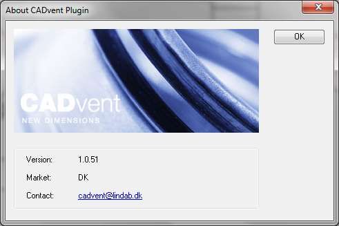
About
In the About button you can find information regarding version number of the CADvent
plugin, which market is installed and contact information for technical assistance.
CADvent plugin About dialog
22/22You can also read