Volume 10, Issue 4, April 2021 - IJIRSET
←
→
Page content transcription
If your browser does not render page correctly, please read the page content below

Volume 10, Issue 4, April 2021
International Journal of Innovative Research in Science, Engineering and Technology (IJIRSET)

                       | e-ISSN: 2319-8753, p-ISSN: 2320-6710| www.ijirset.com | Impact Factor: 7.512|

                                        || Volume 10, Issue 4, April 2021 ||

                                      DOI:10.15680/IJIRSET.2021.1004122

   IOT Based Transformer Monitoring System
                Using Arduino
    Omkar Gaikwad1, Namit Dubey2, Piyush Chhatre3, Shubham Dongare4, Dr.Priyanka Kothoke5
      U.G. Student, Department of Electrical Engineering, Mahatma Gandhi Mission College of Engineering and
                                      Technology, Kamothe, Navi Mumbai, India1
      U.G. Student, Department of Electrical Engineering, Mahatma Gandhi Mission College of Engineering and
                                      Technology, Kamothe, Navi Mumbai, India2
      U.G. Student, Department of Electrical Engineering, Mahatma Gandhi Mission College of Engineering and
                                      Technology, Kamothe, Navi Mumbai, India3
      U.G. Student, Department of Electrical Engineering, Mahatma Gandhi Mission College of Engineering and
                                      Technology, Kamothe, Navi Mumbai, India4
   Assistant Professor, Department of Electrical Engineering, Mahatma Gandhi Mission College of Engineering and
                                      Technology, Kamothe, Navi Mumbai, India5

ABSTRACT: In this project, the design aspects of an embedded device that can monitor the Distribution Transformer
and record the parameters of a distribution transformer like load currents, voltage, and ambient temperature. The main
objective of the project is to control the Distribution Transformer using wireless technology. The aim of the project is
to on, off, and monitor the parameters like load voltage, load current, and temperature of the Distribution Transformer
by using IOT. It is installed at the distribution transformer site and the given parameters are recorded by using the
Arduino Mega microcontroller. The controller is extremely handy at places where we have to control the ON and OFF
switching of the devices but no wired connection to that place is available. IoT-controlled Distribution Transformer is
an automatic control system that is capable of receiving a set of command instructions in the form of the internet of
things and performs the necessary actions like monitoring, ON, and OFF. The transformer monitoring system is a safe
and easy approach to help in easy operation and identification of problems before any costly failure. [1,6].

KEYWORDS: Distribution Transformer, Internet of Things, Health Monitoring, Matlab, Arduino Mega
Microcontroller

                                                I. INTRODUCTION

As we all know that electricity has become an essential need for us in the past recent years, and to fulfil the demand all
over the world, the electrical power system is spread all over. To meet the needs of the end-users there is a transfer of
large electrical power from generating station via a distribution system. The Transformer is the key component of this
distribution system, thus it is essential to monitor the parameters to keep them safe from any fault condition. These
faults must be foreseen and safety precautions applied to the power system. Distribution Transformers are directly
connected to load; hence they are more prone to faults due to sudden load variations. As of now, the distribution
transformers are monitored manually which cannot give the correct value of some parameters such as current overload,
overheating of transformer which has a significant effect on its life. The transformers must be operated in rated
condition for their long life. This is not possible during the entire working period. Overloading and deficient cooling of
transformers can cause unexpected failure in transformers which can disturb the delivery of electricity over many
consumers. The manual check-up of the rise in voltage, rise in ambient temperature, load current, etc. tends to be more
complex as incidental parameters cannot be accessed.An electrical power system consists of various components such
as generators, switches, transmission cables, transformers, capacitor banks among other components. It cannot,
therefore, operate without an effective protective device to keep these components safe and the system stable. Faults in
a power system refer to the undesired conditions that occur in the electrical power system. These conditions may

IJIRSET © 2021                                     |   An ISO 9001:2008 Certified Journal |                         3711
International Journal of Innovative Research in Science, Engineering and Technology (IJIRSET)

                       | e-ISSN: 2319-8753, p-ISSN: 2320-6710| www.ijirset.com | Impact Factor: 7.512|

                                        || Volume 10, Issue 4, April 2021 ||

                                      DOI:10.15680/IJIRSET.2021.1004122
include short circuits, over current, overvoltage, high temperatures among others. Here IOT is used for communicating
the monitored parameters [7,8]

This paper is about the real-time monitoring of the distribution transformer, and to reduce human labour and error to
enhance its life span.

                                      II. TRANSFORMER FAULT ANALYSIS

There are many types of faults a distribution transformer undergoes, in which some of them are the major faults,
which should be checked regularly and monitored to minimize or avoid them. Some of the major faults are shown
below:

   i.    Over Load:
         Over load/ over current is the current flowing through the transformer resulting from faults on the power
         system. Usually this type of fault condition is short in duration (Less than 2 seconds) because the protection
         relay operates and isolate the faults from system. Fault currents that do not include ground are generally in
         excess of four times full-load current.

  ii.    Over / Under Voltage:
         The flux in the transformer core is directly proportional to the applied voltage and inversely proportional to the
         frequency. Over excitation can occur when the per-unit ratio of voltage to fre-quency (Volts/Hz) exceeds 1.05
         p.u. at full load and 1.10 p.u. at no load.

 iii.    Temperature:
         Excessive load current alone may not result in damage to the transformer if the absolute temperature of the
         windings and transformer oil remains within specified limits. Transformer ratings are based on a 24-hour
         average ambient temperature of 30°C (86°F). Due to over voltage and over current, temperature of oil
         increases which causes failure of insulation of transformer winding.

                                              III. PROPOSED SYSTEM

      Fig 1. Shows the block diagram of the proposed system for screening the important parameters of distribution
transformer. The model is based on a microcontroller that monitor the value of voltage, current, and temperature, and
display it on LCD Screen using THINKSPEAK. The monitored values provided by the microcontroller is compared
with the rated values of the transformer and microcontroller is programmed in such a way that when monitored values
exceed the rated values it takes the appropriate action and display the values on the LCD. The microcontroller is
programmed in such a manner so as to continuously take the parameter values at regular time interval.

                                                       Fig 1. Block Diagram

IJIRSET © 2021                                     |   An ISO 9001:2008 Certified Journal |                          3712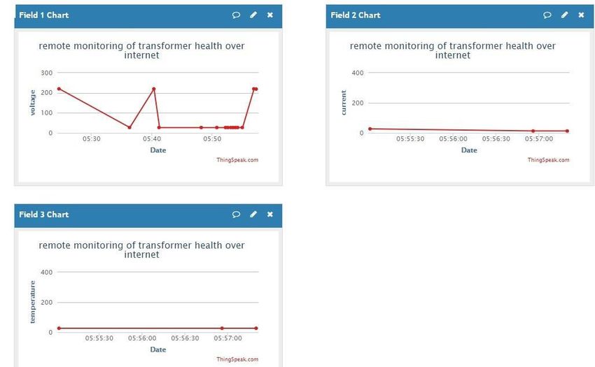
International Journal of Innovative Research in Science, Engineering and Technology (IJIRSET)
| e-ISSN: 2319-8753, p-ISSN: 2320-6710| www.ijirset.com | Impact Factor: 7.512|
|| Volume 10, Issue 4, April 2021 ||
DOI:10.15680/IJIRSET.2021.1004122
Transformer:The transformer used in this model is for step down the 220V ac into 12V ac as the microcontroller
cannot work on so high voltage. It consists of two windings and works on the principle of mutual induction.
Bridge Rectifier:The bridge rectifier is used for converting the ac voltages into dc and is connected at the output of
transformer.
Blocking Diode: The blocking diode is used for blocking the reverse polarity current.
Voltage Regulator: The voltage regulator is used for regulating the 12V dc into 5V dc. It is connected at the output of
bridge rectifier, the LM 7805 voltage regulator have been using in this system.
LCD Display: The LCD display is used for displaying the monitoring data such as temperature, current and voltage
etc. of the connected transformer.
Microcontroller PIC 18F452: The microcontroller is used for the intelligent control ofthis system. It 40 pins
microcontroller and is programmed in c language with the help of mikro/c software. It is powered up with 5V dc and is
interfaced with Wi-Fi module, ADC 0808 and LCD display.
ADC 08080: The ADC 0808 is used for converting the analogue data into digital data for giving the logic signal to the
microcontroller. It is 16 pin integrated circuit IC and is powered up with 5V dc.
Wi-Fi Module:The wi-fi module is used connecting this system to the wi-fi network for the remote monitoring of data
of transformer or generator. It is interfaced with microcontroller for receiving the logic data.
Temperature Sensor:The temperature sensor is used for sensing the temperature of cross ponding transformer. For
this purpose, the LM 35 temperature sensor have been using here.
Voltage Sensor:The voltage sensor is used for sensing the voltage of corresponding components such as transformer.
Current Sensor: The current sensor is used for sensing the current of cross ponding transformer or generator. It senses
the current in amps and give output in milli amps. It is interfaced with ADC 0808 for giving him analogue input.
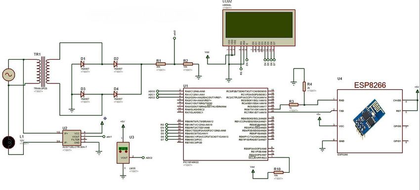
IV. CIRCUIT DIAGRAMS
Fig 2. Interfacing Current, Voltage, Temperature Sensors and LCD with Microcontroller.
IJIRSET © 2021 | An ISO 9001:2008 Certified Journal | 3713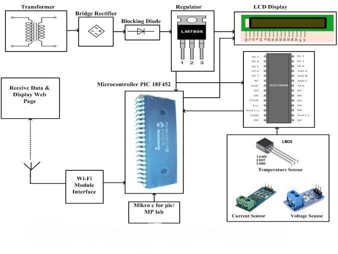
International Journal of Innovative Research in Science, Engineering and Technology (IJIRSET)

                       | e-ISSN: 2319-8753, p-ISSN: 2320-6710| www.ijirset.com | Impact Factor: 7.512|

                                        || Volume 10, Issue 4, April 2021 ||

                                     DOI:10.15680/IJIRSET.2021.1004122
                             V. ALGORITHM FOR CENTRALIZED MONITORING

   The step by step procedure for monitoring the distribution transformer key parameters like voltage, current and
temperature are explained as follows and also with the help of the flowchart.
   STEP 1: Start.
   STEP 2: Check the connection.
   STEP 3: Verify the hardware for the power supply to the kit.
   STEP 4: Input the Potential Transformer, Current Transformer, and Temperature Sensor.
   STEP 5: Transfer the values of Potential Transformer, Current Transformer, and Temperature Sensor to
            THINKSPEAK channel.
   STEP 6: If the voltage and current values exceeds rated values which are specified in pic program, suitable action is
            Taken by the microcontroller.
   STEP 7: If the temperature exceeds specified rated value, suitable action is taken by the microcontroller.
   STEP 8: These data are stored and displayed on LCD using in the Matlab Simulink.
   STEP 9: Stop

                                                VI. OBSERVATION

  1. Sensors are initialised to sense current, voltage & temperature of transformer.
  2. Microcontroller continuously update & display readings on pc.
  3. If transformer parameters such as current and voltage exceeds rated values microcontroller is programmed in such
    a way that it stops power supply.
  4. If temperature parameter exceeds rated value microcontroller is programmed in such a way that it turns on cooling
    fan[1].

                                                Fig 3. Observed Values

IJIRSET © 2021                                    |   An ISO 9001:2008 Certified Journal |                         3714
International Journal of Innovative Research in Science, Engineering and Technology (IJIRSET)
| e-ISSN: 2319-8753, p-ISSN: 2320-6710| www.ijirset.com | Impact Factor: 7.512|
|| Volume 10, Issue 4, April 2021 ||
DOI:10.15680/IJIRSET.2021.1004122
VII. CONCLUSION
Transformers are among the most generic and expensive piece of equipment of the transmission and distribution
system. Regular monitoring health condition of transformer not only is economical also adds to increased reliability. In
this paper, the distribution transformer key parameters like voltage, current and temperature are monitored using PIC
18F452 microcontroller. This model protects the transformer from the over loading and overheating. This can be very
crucial in transformer health system and extending its life.
REFERENCES
[1] Sashank Shekhar, Somvanshi, & Dr. Deependra Pandey. (2017). A simulink based system to monitor parameters
of transformer. International Journal of Innovative Research in Science, Engineering and Technology, 6(Special
Issue-9), 51-54.
[2] V.A. Patil, Namrata S. Kumbhar, & Shital S. Patil. (2017). Transformer monitoring and controlling with Gsm
based system. International Research Journal of Engineering and Technology, 4(3), 119-123.
[3] Vadirajacharya. K, Ashish Kharche, Harish Kulkarni, & Vivek Landage. (2012). Transformer health condition
monitoring through gsm technology. International Journal of Scientific and Engineering Research, 3(12), 1-5.
[4] Dr. J.Jayakumar, J. Hephjiba Jose Queen, Thanu James, G. Hemlata, & Neetu lonappan. (2013). Distribution
transformer monitoring using gprs. International Journal of Scientific and Engineering Research, 4(6), 1199-1204.
[5] M. Banupriya, R. Punitha, B. Vijayalakshmi & C. Ramkumar. (2013). Power transmission monitoring system
using zigbee. Global Journal of Researches in Electrical and Electronic Engineering, 13(16), 16-26.
[6] Pathak A. K, Kolhe A.N, Gagare J. T, & Khemnar S. M. (2016). Gsm based distribution transformer monitoring
and controlling. International Journal of Advance Research and Innovative Ideas in Education, 2(2), 349- 351.
[7] Ashish C. Jangam, Prof. D.G. Chougule and Prof. A.S. Mali 2018 Transformer Parameters Monitoring System
using MATLAB Simulink International Journal of Engineering and Management Research Page Number: 11-15
[8] Mr. Ankush Rameshrao Kadam, Mr. Aditya Ganesh Survase, Mr. Swapnil Mahadev Patekar 2019 Transformer
Monitoring System Using Arduino Resincap Journal of Science and Engineering, 546-552
IJIRSET © 2021 | An ISO 9001:2008 Certified Journal | 3715You can also read