CAL1 User Manual 11. February 2021 - Image Engineering
←
→
Page content transcription
If your browser does not render page correctly, please read the page content below
CAL1
                          User Manual

                    11. February 2021

Image Engineering GmbH & Co. KG · Im Gleisdreieck 5 · 50169 Kerpen-Horrem · Germany

        T +49 2273 99991-0 · F +49 2273 99991-10 · www.image-engineering.com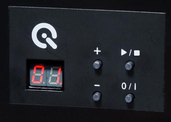
Content

1    INTRODUCTION ................................................................................................................ 3
    1.1    Conformity ................................................................................................................... 3
    1.2    Intended use ................................................................................................................ 3
      1.2.1      Departing from described setup............................................................................ 3
      1.2.2      USB connection .................................................................................................... 3
    1.3    General Safety Information .......................................................................................... 4
2    GETTING STARTED ......................................................................................................... 4
    2.1    Scope of delivery ......................................................................................................... 4
3    OPERATING INSTRUCTIONS HARDWARE .................................................................... 5
    3.1    Overview display and ports .......................................................................................... 5
    3.2    Connecting the hardware ............................................................................................. 6
    3.3    Camera positioning ...................................................................................................... 7
4    OPERATING INSTRUCTIONS SOFTWARE..................................................................... 7
    4.1    Requirements .............................................................................................................. 7
    4.2    Software installation ..................................................................................................... 7
    4.3    Starting the system ...................................................................................................... 7
      4.3.1      Spectrometer settings ........................................................................................... 7
      4.3.2      Spectrometer calibration ....................................................................................... 7
      4.3.3      iQ-LED calibration................................................................................................. 8
    4.4    Low intensity use ......................................................................................................... 8
5    ADDITIONAL INFORMATION ........................................................................................... 9
    5.1    Maintenance ................................................................................................................ 9
    5.2    Care instructions .......................................................................................................... 9
    5.3    Disposal instructions .................................................................................................... 9
6    TECHNICAL DATA SHEET ............................................................................................. 10

Image Engineering                                                CAL1                                              Seite 2 von 10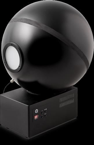
Introduction

1 INTRODUCTION
       Important information: Read the manual carefully before using the device.
       Inappropriate utilization may cause damages to the device, to the DUT (device under test)
       and/or other components of your setup.
       Keep these instructions in a safe place and pass them to any future user.

1.1    Conformity
       We, Image Engineering GmbH & Co. KG, hereby declare, that the CAL1 corresponds to the
       essential requirements of the following EC directive in its current version:
           •    Electromagnetic Compatibility - 2014/30/EU
           •    RoHS 2 - 2011/65/EU
           •    Low Voltage - 2014/35/EU

1.2    Intended use
       The integrating sphere is designed as a calibration light source, based on iQ-LED technology. It
       includes a micro spectrometer and is controlled with the iQ-LED control software or via dip
       switches when not connected to a PC.
           •    Only suitable for indoor use.
           •    Place your system in a dry and constant tempered environment without any interfering
                light.
           •    The optimal ambient temperature range is 22 to 26 degrees Celsius. The maximum
                ambient temperature range is 18 to 28 degree Celsius.
           •    The optimal system temperature range, displayed in the software user interface, is
                between 35 and 50 degrees Celsius. The system has internal temperature
                management, if there is any error regarding the internal temperature, you will get a
                warning message and the system will automatically shut off to avoid any damage.

  1.2.1    Departing from described setup
       The following steps must be performed in the correct chronology to allow a frictionless
       commissioning. Departing from the chronology may lead to an incorrect working device.
           1. Install the iQ-LED software
           2. Connect CAL1 to power and via USB to the PC
           3. Switch CAL1 on; the system drivers will now be installed
           4. After drivers are installed completely, start the software

  1.2.2    USB connection
       Only appropriate USB connection allows error-free operation of CAL1. Use delivered USB
       cables. If you need to extend the USB connection to longer distances, please check if powered
       hubs/repeaters are necessary.

Image Engineering                                  CAL1                                 Seite 3 von 10
Getting started
1.3 General Safety Information
WARNING!
Some LEDs are emitting invisible light in the IR and UV near area.
• Do not look directly into the emitted light or look through the optical LED system.
• Do not look directly in the open sphere or light source when using high intensities
or sequences with low response time.
• Do not open the device without any instructions from the Image Engineering
support team or when connected to the power supply.
2 GETTING STARTED
2.1 Scope of delivery
• integrating sphere
• spectrometer (built-in)
• power cord
• USB cable
• control software
• calibration protocol
Optional equipment:
• iQ-Align for CAL1 for a quick and easy camera alignment.
iQ-Align for CAL1
• EX2 spectrometer for external measurements.
• iQ-Trigger: The iQ-Trigger is a mechanical finger that can press the release button
within 25 ms. When working with touchscreens, exchange the solid fingertip for a touch-
pen tip.
• iQ-Analyzer software (shading module)
This module includes a special chart layout file that allows analysis of images with and
without a keyhole effect.
Image Engineering CAL1 Seite 4 von 10Operating instructions hardware
3 OPERATING INSTRUCTIONS HARDWARE
3.1 Overview display and ports
• 1 x USB port for software control
• 1 x port for power adapter
• 1 x trigger output
Use the control panel to set different light settings for the iQ-LED´s:
• with the “+” and “-“ buttons you can switch between 44 saved illuminants
• numerical display to show the storage of the illuminants
• with the play and stop button you can start and stop a saved light sequence with
different illuminants (it is possible to save one sequence on the device)
• with the power button, you can turn on and off the light
• there are three pre-stored illuminants on your device (the intensity of each illuminant is
shown in the acceptance protocol of your device):
o 1: illuminant A (default illuminant)
o 2: illuminant D50
o 3: illuminant D75
Note: To store your own generated illuminants or sequences on your device, please follow the
instructions in the iQ-LED SW user manual.
Image Engineering CAL1 Seite 5 von 10Operating instructions hardware
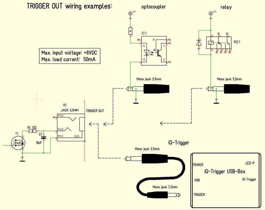
Wiring examples for the trigger output:
Trigger OUT wiring examples
The default duration value for the trigger output is 500 ms. This value can be modified with
the iQ-LED API. A signal is send out to the trigger output while changing the illuminats or the
intensity of LED channels. It can be used to synchronize your test setup. For example with
an iQ-Trigger. (See 2.1 optional equipment)
3.2 Connecting the hardware
1. Connect the power cord to the power supply on the back of CAL1.
2. Connect the USB cable to the CAL1 and your PC.
3. Turn on the CAL1; the power switch is located beside the power supply.
4. Connect the spectrometer to the PC using the USB cable. The system will install the
spectrometer and iQ-LED drivers on your PC, this will take a few seconds.
5. You can check the installation in your hardware manager.
Hardware Manager: active iQ–LED and spectrometer
Image Engineering CAL1 Seite 6 von 10Operating Instructions Software
3.3 Camera positioning
• your DUT should be as close as possible to the CAL1 diffusor
• the lens should be exactly in the middle of the diffusor
If these requirements are not fulfilled, an inhomogeneous illuminated field of view will occur. The
easiest way to align the camera correctly is to use the optional iQ-Align. (see 2.1)
4 OPERATING INSTRUCTIONS SOFTWARE
4.1 Requirements
• PC with Windows 7 (or higher) operating system
• one free USB port
4.2 Software installation
Install the iQ-LED control software before connecting the hardware. Follow the setup instruction
from the iQ-LED control software manual.
4.3 Starting the system
Start the iQ-LED software by clicking the ‘iQ-LED.exe’ or the iQ-LED icon on your desktop.
Follow the iQ-LED software manual to control the CAL1.
NOTE
The iQ-LED devices can only operate with high precision, when setup and calibration
are performed correctly.
Consult the iQ-LED software manual for a comprehensive description and read it
carefully.
4.3.1 Spectrometer settings
The iQ-LED software (see iQ-LED software manual) automatically generates the best
spectrometer settings for you lighting conditions after pressing the “auto detect” button. For
special applications, it is also possible to set the spectrometer settings manually. If you have
further question, please contact the Image Engineering support.
4.3.2 Spectrometer calibration
Your spectrometer comes fully NIST traceable calibrated. We recommend recalibrating the
spectrometer once a year, regardless of the operating hours. If a spectrometer calibration is
required, please contact Image Engineering.
Note: Before removing the spectrometer, measure and note the lux value of a predefined
standard illuminant.
Image Engineering CAL1 Seite 7 von 10Operating Instructions Software
After the spectrometer is calibrated and has been reinstalled to your system, perform a spectral
calibration (iQ-LED calibration) and check if this intensity value is still correct. If it is not correct,
you have to perform a lux calibration.
4.3.3 iQ-LED calibration
The individual LED lights of the iQ-LED inside the CAL1 depends on many different types and
wavelengths. Some LEDs will change their intensity level and peak wavelength slightly in the
first 500-600 working hours because of a burn-in effect.
The LEDs will also degrade in intensity during their lifetime. To make sure that all
measurements including the auto-generated illuminants and the standard illuminants, are
correct, you have to perform a spectral calibration regularly.
You must also consider the degradation of the LED when saving self-defined presets. If you
save a preset with LED channels that uses its maximum intensity, the possibility exists that this
intensity cannot be reached after the burn-in time or the long-time degradation of the LED. In
this case, you will get a warning message from the iQ-LED control software.
During the first 500-600 working hours, we recommend performing a spectral calibration every
50 operating hours.
After the first 500-600 operating hours, a calibration of every 150 working hours suffices.
Other factors that indicate the need for a spectral calibration: unsatisfactory illuminant
generation, the aberration of the intensity values, or a spectral curve that does not fit with the
predefined standard illuminants of the corresponding preset.
• the spectrometer works correctly
• the spectrometer settings are correct
• all LED channels work correctly
• the dark measurement is correct
• your measurement environment is correct
• your ambient temperature is correct
How to perform the spectral calibration is described in the iQ-LED control software manual.
4.4 Low intensity use
When using your system with very low intensity, the spectral measurement values will start to
fluctuate. The lower the intensity, the higher the fluctuation. The generated light is still stable up
to a certain point. The fluctuation of the values is caused by the noise of the spectral
measurement of the internal spectrometer. The light intensity will continue to get lower when the
influence of the noise continues to get higher. When using standard illuminants with an intensity
lower than 25 lx, it will no longer be possible to get a correct value.
Image Engineering CAL1 Seite 8 von 10Additional information
5 ADDITIONAL INFORMATION
5.1 Maintenance
The spectrometer requires a recalibration once a year, regardless of the operating hours. If a
spectrometer calibration is necessary, please contact Image Engineering.
Please send the complete device to Image Engineering.
Pack the CAL1 with a notation for calibration in the hard case it was delivered in.
Please contact support@image-engineering.de for conditions and procedure.
5.2 Care instructions
• Do not touch, scratch, or pollute the diffusor.
• If there is any dust on the diffusor, clean it with an air blower.
• Do not remove the fiber from the spectrometer. Otherwise, the calibration is invalid, and
the spectrometer has to be recalibrated!
• Only store and transport the CAL1 in the delivered hard case.
5.3 Disposal instructions
After the service life of CAL1, it must be disposed of properly. Electrical and electromechanical
components are included in CAL1. Observe your national regulations. Make sure that CAL1
cannot be used by third parties after disposing of it.
Contact Image Engineering if assistance for disposal is required.
Image Engineering CAL1 Seite 9 von 10Technical data sheet
6 TECHNICAL DATA SHEET
See annex for the technical data sheet. It can also be downloaded from the website of Image
Engineering: www.image-engineering.com.
Image Engineering CAL1 Seite 10 von 10You can also read