High efficiency reversible air/water heat pumps type Geyser Max - Technical information manual
←
→
Page content transcription
If your browser does not render page correctly, please read the page content below
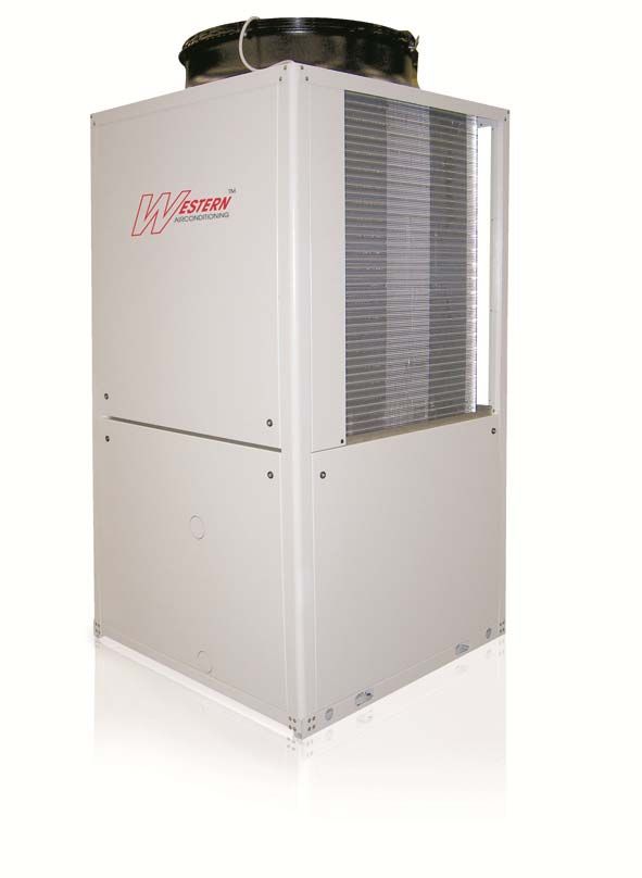
High efficiency reversible air/water heat
                        pumps
                   type Geyser Max

                                          Technical information manual

___________________________________________________________________________________________
       Western Airconditioning B.V. Hoevelaken Tel. (033) 247 78 00   E-mail: sales@western.nl   www.western.nl
2
Technical information manual GEYSER MAX
REF. GEYSER-MAX-10213600202_03.10/GEYSER_MAX_2011.DOC
GEYSER MAX
Reversible heat pump
for the production of high temperature water
Index
Specifications 120
General specifications - basic version 124
Electrical specifications - basic version 125
Cooling capacity 126
Heating capacity 127
Operating limits 128
Noise levels 129
Overall dimensions, weights, safety
distances and hydraulic connections 130
Practical advice on installation 133
___________________________________________________________________________________________
Western Airconditioning B.V. Hoevelaken Tel. (033) 247 78 00 E-mail: sales@western.nl www.western.nl3
Technical information manual GEYSER MAX
REF. GEYSER-MAX-10213600202_03.10/GEYSER_MAX_2011.DOC
Specifications
GEYSER MAX
High efficiency air/water heat pumps
Air-condensed water cooler unit, compact in size, featuring hermetic scroll compressors, an axial fan and a plate
evaporator. Cooling fluid: R410A.
BODY
Galvanised metal sheet painted with polyester dust RAL 7035 at 180°C, which make it highly resistant to weather
conditions. Panels installed on all four sides are easy to remove in order to guarantee access to internal components.
COMPRESSORS
Steam injection hermetic scroll components complete with a thermal protection in the coils of the electrical motor, a
heater for the casing and rubber vibration dampers. These compressors are provided with a connection to the steam
injection unit in order to achieve higher temperatures compared to standard compressors. From a thermodynamic
standpoint, steam injection also allows for greater energy efficiency levels. The unit consists in two separate circuits
to ensure greater reliability.
HEAT EXCHANGER ON SOURCE SIDE
The heat exchanger consists of a coil featuring copper tubes and aluminium fins and is provided with a large exchange
surface. The coil is characterised by two or three separate and staggerred rows which allow for higher heat exchange.
The coil also features two separate circuits which create two indipendent circuits. A subcooler is installed at the base
of the coil to allow for total defrosting, while an anti-freeze heater ensures condensation water flow towards the drain.
FANS
Axial flow fans directly coupled to the 6-pin electric motor featuring an external rotor, protection level IP54. The fan is
made with an aluminium body to make it lighter and blades in polymeric material. This solution significantly reduces
vibration levels and noise emissions. The fan houses a shaped nozzle and kincludes a safety protection grid in line
with standard UNI EN 294.
HEAT EXCHANGER ON OPERATION SIDE
Braze-welded stainless steel AISI 316 plates insulated by a shell of closedcell foam material. This is a two-circuit heat
exchanger, i.e. it features two independent internal circuits. This feature not only increases the unit reliability, but also
offers great advantage in terms of energy consumption. The heat exchanger is provided with a temperature probe for
protection against freezing and a flow switch standardly supplied with the exchanger.
REFRIGERANT CIRCUIT
The circuit includes: a fluid intake into the line and aspiration, a fluid light, a dehydrator filter, thermal expansion valves
with an external pressure equalization system, a 4-way inversion valve, a fluid accumulator, an intake separator, check
valves, a solenoid valve in the fluid line, a pressure transducer, high and low pressure switches and a safety valve. It
also features a refrigerant-refrigerant exchanger that produces steam for compressor cooling.
___________________________________________________________________________________________
Western Airconditioning B.V. Hoevelaken Tel. (033) 247 78 00 E-mail: sales@western.nl www.western.nl4
Technical information manual GEYSER MAX
REF. GEYSER-MAX-10213600202_03.10/GEYSER_MAX_2011.DOC
Specifications
ELECTRICAL PANEL
Features a general circuit-breaking device, a protection of power and auxiliary circuits and a remote compressor
control switch. The unit is microprocessor controlled and is equipped with a function display.
The electrical panel consists of:
• a general circuit-breaking device and fuses to protect the power and auxiliary circuits;
• a remote compressor control switch;
• a fan turn controller for condensation control;
• general alarm contacts;
• a microprocessor to control the following functions:
- water temperature setting with inlet water control;
- an anti-freeze protection;
- compressor timers;
- a high pressure alert manager (to prevent the unit from stopping);
- a switch for winter-to-summer switching and/or vice versa;
- automatic defrosting;
- alarm signals;
- alarm reset;
- self-adjusting controller to enable optimised operation even when the water level in the unti is low;
- a digital input for external ON-OFF switching;
- a digital input for winter-to-summer switching and/or vice versa.
Parameters shown in the display:
- Outlet water temperature;
- input water temperature;
- condensation temperature;
- temperature and differential setpoints;
- alarm description;
- compressor hour meter;
• 400V/3~/50Hz power supply for all sizes.
CONTROLS AND SAFETY DEVICES
• Water temperature probe on user side (located at heat exchanger inlet)
• Anti-freeze probe triggering anti-freeze alarm (automatic resetting, limited maintenance)
• High pressure switch (manual resetting)
• Low pressure switch (manual resetting, limited maintenance)
• Flow switch alarm due to low water rate (manual resetting)
• Condensation pressure control by means of turn controller for operation at low external temperatures
• High pressure safety valve
• Internal protection against compressor overpressure
• External protection against compressor overpressure
TESTING
The units are factory-tested and supplied complete with oil and refrigerant.
Testing consists in the following activities:
• leak test: the circuit is pressurised and welds are tested for tightness;
• operating test in Chiller mode (refrigerating capacity, absorbed power, head loss, etc.);
• operating test in Heat Pump mode (heating capacity, absorbed
power, etc.);
• inspection for the causes of safety device engagement.
___________________________________________________________________________________________
Western Airconditioning B.V. Hoevelaken Tel. (033) 247 78 00 E-mail: sales@western.nl www.western.nl5
Technical information manual GEYSER MAX
REF. GEYSER-MAX-10213600202_03.10/GEYSER_MAX_2011.DOC
Versions
Consult the configuration table to check whether an option interferes with other configurations.
HYDRAULIC MODULE OPTIONS
GEYSER MAX /LN:
Low Noise Unit
In addition to the components of the basic version, this unit has a fully soundproofed compressor compartment using
high acoustic impedance and sound-absorbent materials.
Accessories
REFRIGERANT CIRCUIT ACCESSORIES
• Tap in liquid line
• Electronic thermostat valve
• Dual setpoint
HYDRAULIC CIRCUIT ACCESSORIES
• Filling unit with pressure gauge
• Anti-freeze seal
ELECTRICAL ACCESSORIES
• Phase monitor
• Serial interface RS485
• Remotly-controlled user terminal panel (in addition to panel installed on machine)
• User interface
• Setpoint compensation depending on external air temperature
• Automatic management of domestic hot water
OTHER ACCESSORIES
• Rubber vibration dampers
• Packaging in wooden crate
___________________________________________________________________________________________
Western Airconditioning B.V. Hoevelaken Tel. (033) 247 78 00 E-mail: sales@western.nl www.western.nl6
Technical information manual GEYSER MAX
REF. GEYSER-MAX-10213600202_03.10/GEYSER_MAX_2011.DOC
General specifications basic version
(1) External air temperature 7°C BS, 6°C BU; condenser input-output water temperature 30-35°C
(2) The total power is the sum of the power absorbed by the compressors and the fans.
(3) External air temperature 7°C BS, 6°C BU; condenser input-output water temperature 40-45°C
(4) External air temperature 7°C BS, 6°C BU; condenser input-output water temperature 60-65°C
(5) External air temperature 35°C; evaporator inlet-outlet water temperature 23-18°C
(6) External air temperature 35°C; evaporator inlet-outlet water temperature 12-7°C
(7) Noise power levels measured according to standard ISO 3744 under nominal operating conditions.
(8) Noise pressure levels refer to the values measured at a location 10 metres away from the unit in free field under
nominal operating conditions according to ISO 3744.
This data sheet gives the characteristic data of the basic and standard versions of the range; for more details please refer to the specific documentation.
___________________________________________________________________________________________
Western Airconditioning B.V. Hoevelaken Tel. (033) 247 78 00 E-mail: sales@western.nl www.western.nl7
Technical information manual GEYSER MAX
REF. GEYSER-MAX-10213600202_03.10/GEYSER_MAX_2011.DOC
Electrical specifications basic version
(1) Electrical power that must be supplied by the mains to power the unit.
(2) Current at which the internal unit protections cut in. This is the max. current absorption by the unit. This value is never exceeded and must be
used to size the line and relative protections (refer to the electrical diagram supplied with the units).
(3) Maximum inrush current calculated considering the compressor start-up requiring greater power and the max. current absorbed by all other
devices.
___________________________________________________________________________________________
Western Airconditioning B.V. Hoevelaken Tel. (033) 247 78 00 E-mail: sales@western.nl www.western.nl8
Technical information manual GEYSER MAX
REF. GEYSER-MAX-10213600202_03.10/GEYSER_MAX_2011.DOC
Cooling Capacities standard unit
All data refer to the basic version
Pf: cooling capacity [kW]
Pe: electrical power absorbed by the compressors [kW]
To: evaporator output water temperature [°C]
___________________________________________________________________________________________
Western Airconditioning B.V. Hoevelaken Tel. (033) 247 78 00 E-mail: sales@western.nl www.western.nl9
Technical information manual GEYSER MAX
REF. GEYSER-MAX-10213600202_03.10/GEYSER_MAX_2011.DOC
Heating Capacities standard unit
All data refer to the basic version
Pt: heating capacity [kW]
Pe: electrical power absorbed by the compressors [kW]
Ta: dry bulb air temperature at evaporator inlet [°C]
RH: relative air humidity at evaporator inlet [%]
___________________________________________________________________________________________
Western Airconditioning B.V. Hoevelaken Tel. (033) 247 78 00 E-mail: sales@western.nl www.western.nl10
Technical information manual GEYSER MAX
REF. GEYSER-MAX-10213600202_03.10/GEYSER_MAX_2011.DOC
Operating Limits standard unit
Cooling
Heating
The parameters below must be met simultaneously for correct unit operation.
The max. temperature of the input water MUST BE ≤ 60°C, in transients as well.
The thermal gradient MUST RANGE between min. 3.0°C and max. 5.0°C in all operating conditions.
___________________________________________________________________________________________
Western Airconditioning B.V. Hoevelaken Tel. (033) 247 78 00 E-mail: sales@western.nl www.western.nl11
Technical information manual GEYSER MAX
REF. GEYSER-MAX-10213600202_03.10/GEYSER_MAX_2011.DOC
Noise Levels standard units
Lw: noise power values measured in free field calculated according to standard ISO 3744.
Lp: noise pressure values measured at a 10 m distance from the unit in free field according to standard ISO 3744.
___________________________________________________________________________________________
Western Airconditioning B.V. Hoevelaken Tel. (033) 247 78 00 E-mail: sales@western.nl www.western.nl12
Technical information manual GEYSER MAX
REF. GEYSER-MAX-10213600202_03.10/GEYSER_MAX_2011.DOC
Overall dimensions, weights, safety distances and hydraulic connections
GEYSER MAX 30-40-50-60
___________________________________________________________________________________________
Western Airconditioning B.V. Hoevelaken Tel. (033) 247 78 00 E-mail: sales@western.nl www.western.nl13
Technical information manual GEYSER MAX
REF. GEYSER-MAX-10213600202_03.10/GEYSER_MAX_2011.DOC
Overall dimensions, weights, safety distances and hydraulic connections
GEYSER MAX 30-40-50-60
___________________________________________________________________________________________
Western Airconditioning B.V. Hoevelaken Tel. (033) 247 78 00 E-mail: sales@western.nl www.western.nl14
Technical information manual GEYSER MAX
REF. GEYSER-MAX-10213600202_03.10/GEYSER_MAX_2011.DOC
Practical Advice on Installation
POSITIONING
- Strictly comply with the safety distances indicated in the catalogue.
- Check that there are no obstructions near the finned coil suction or the fan air discharge.
- Place the unit in a manner that assures the lowest environmental impact (noise, integration with nearby structures,
etc.).
ELECTRICAL CONNECTIONS
- Always consult the enclosed wiring diagram, which provides all the instructions required for making the electrical
connections.
- Power up the unit (main switch), at least 12 hours before start-up, in order to turn the crankcase heaters on.
Do not switch the power off during short stoppages.
- Before turning off the main switch, stop the unit by turning off all the operating switches or using the remote control.
- Before accessing on the inner components, switch the power off at the main switch.
- The power supply must be fitted with all statutory protections.
- Electrical connections: three-pole power cable + earth, or three pole cable + neutral + earth; external interlock;
remote alarm signalling.
HYDRAULIC CONNECTIONS
- Carefully vent the hydraulic system with the pump switched off, by turning the air valve. This procedure is particularly
important, as even small air bubbles may cause the evaporator to freeze.
- Drain the system during winter stops or use special anti-freeze solutions. During short stops, it is advisable to install
an electric heater on the evaporator and the hydraulic circuit.
- Install the hydraulic circuit with all the components shown in the diagrams (expansion vessel, flow switch, storage
tank, air valve, shut-off valves, flexible connections, etc. Please refer to the user, installation and maintenance
manual).
- If the flow switch is supplied separately from the units, connect it by carefully following the instructions provided with
the units.
START-UP AND MAINTENANCE
- Strictly follow the instructions given in the operation and maintenance manual. These operations must in any case be
carried out by qualified staff only.
___________________________________________________________________________________________
Western Airconditioning B.V. Hoevelaken Tel. (033) 247 78 00 E-mail: sales@western.nl www.western.nlYou can also read


